3. CNC
This week we have worked on one topic of the computer controlled cutting topics, which is CNC cutting. CNC stands for computerized Numerical Control; which a pre programmed software and code controls the movement of the production equipment. Hence, our instructors explained the theory knowledge about CNC and what is used for.
Helpful CNC design software
On the following list you can find some of the useful design software used in CNC. (1) Grasshopper,is a generative modeling software for rhino. Often used by architects and interior designers. Grasshopper is a visual programming language and environment that runs within the Rhinoceros 3D computer-aided design (CAD) application. The program was created by David Rutten at Robert McNeel & Associates. Programs are created by dragging components onto a canvas. (2) SketchChair, is a free, open-source software tool that allows anyone to easily design and build their own digitally fabricated furniture. (3) Slicer for Fusion, is a software powered by AutoDesk which is a tool to turn your digital 3D models into appealing artefacts. It slices and converts 3D models into 2D patterns that you can cut out of any flat material. Slicer for Fusion 360 also creates 3D instructions you can interact with, to help build a model. (4) MakerCase, is a web-based application for designing laser-cut project cases. Design custom laser-cut cases for your projects.
File formats
Make sure that the design formats converted to G code, are the followings: SVG, DXF, AI, PDF, rml, sbp, g, ord. All these formats work with the program used to run the CNC machine in our lab. we have used DXF.
Looking for a design idea
I have looked for different designs idea, so I can replicate and modify the design I want to do in the 3D software. As I mentioned in my previous assignment that the design software that I am suitable to use and do the CNC is INVENTOR. the following pictures show some of the design that were in my mind. 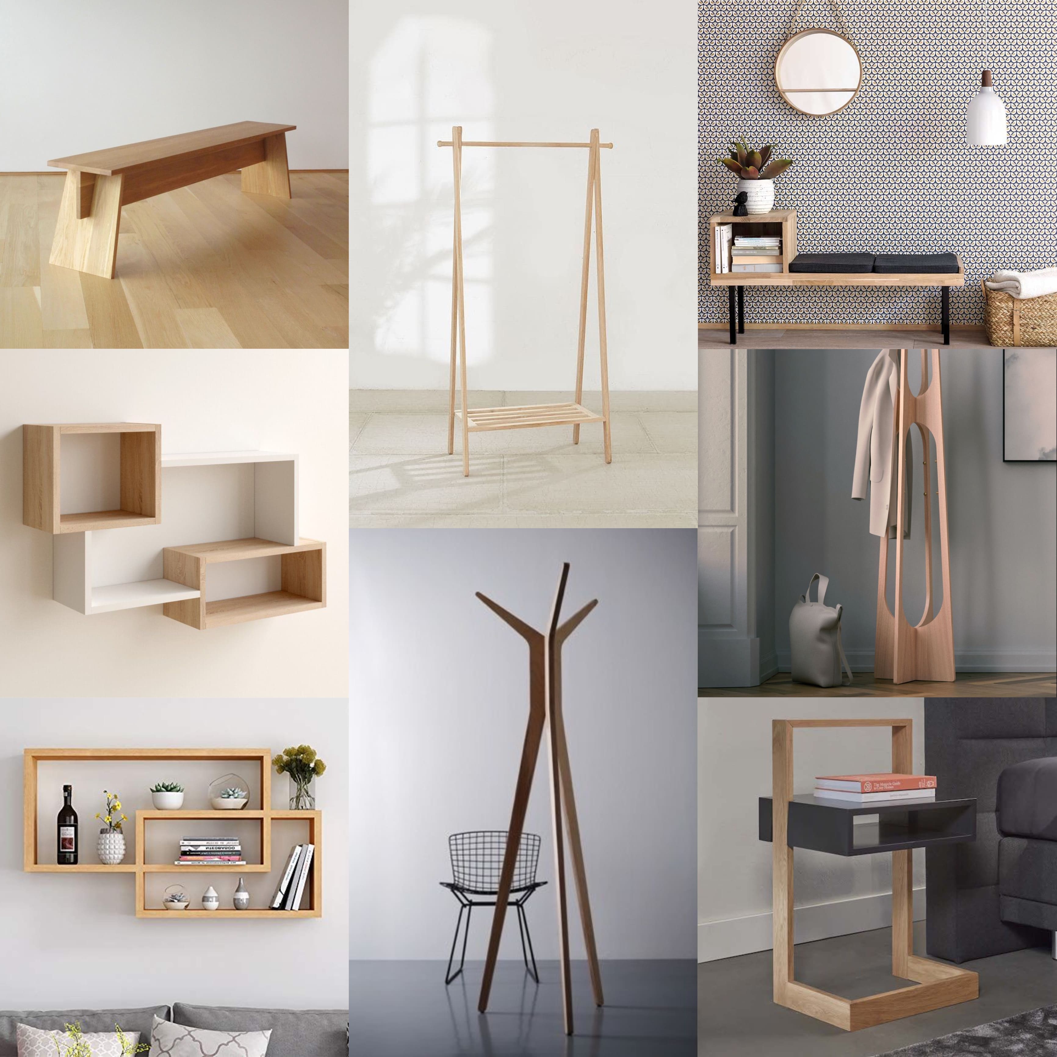
Inventor design
At the beginning I performed a design of a board game which is xo, but the design was not acceptable as it is too simple to preform in the CNC machine. Thus, I chose to do the bench table design for kids. the following steps explain the design stages I have gone through to perform my design.
First
I have developed a 2D sketch for the whole bench in the beginning and extrude all the parts. I have used some of the features such as mirroring some objects which have the same dimensions and design.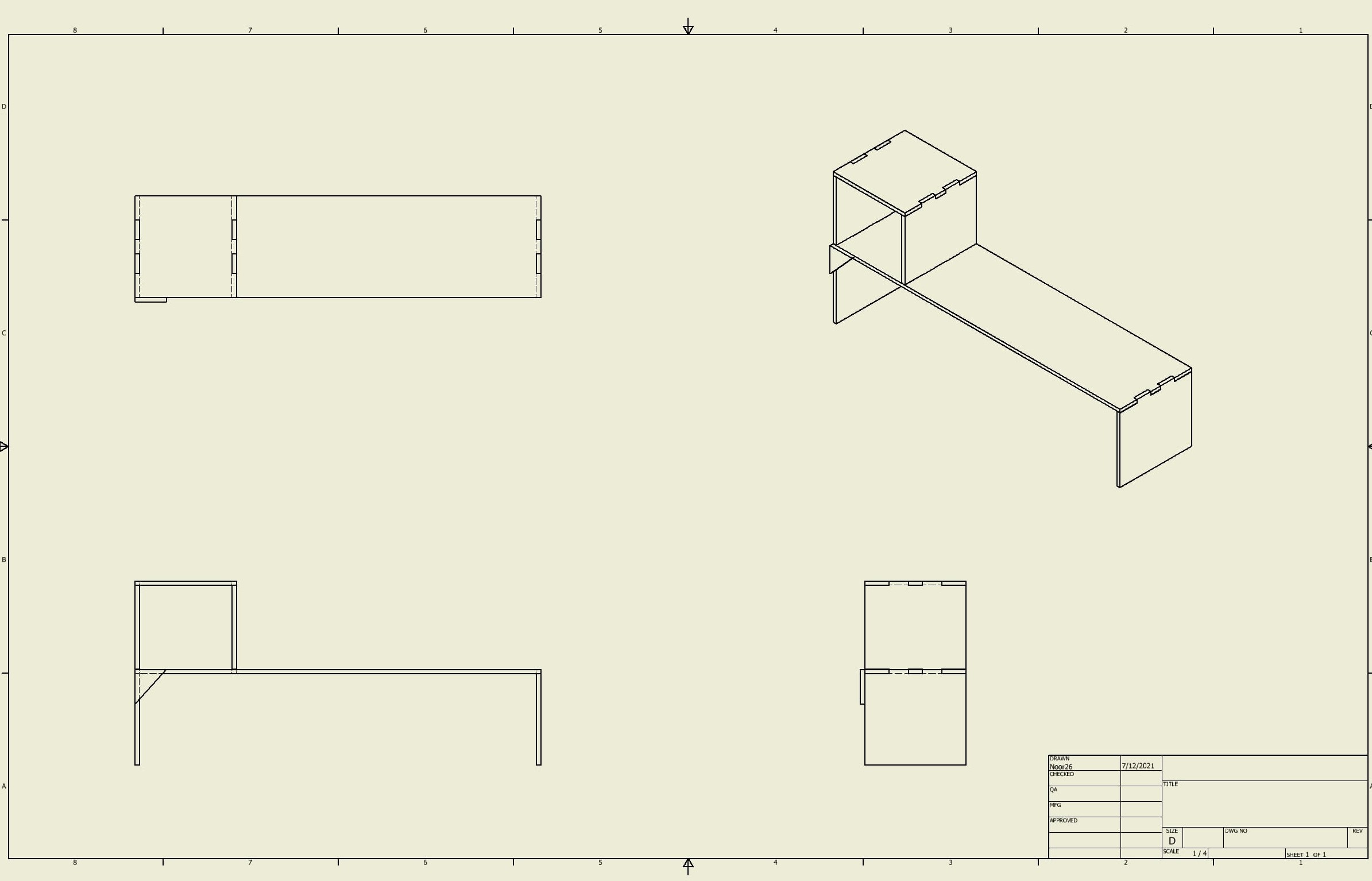
Second
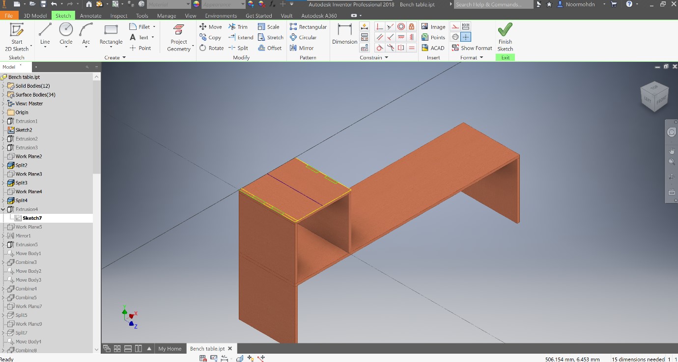
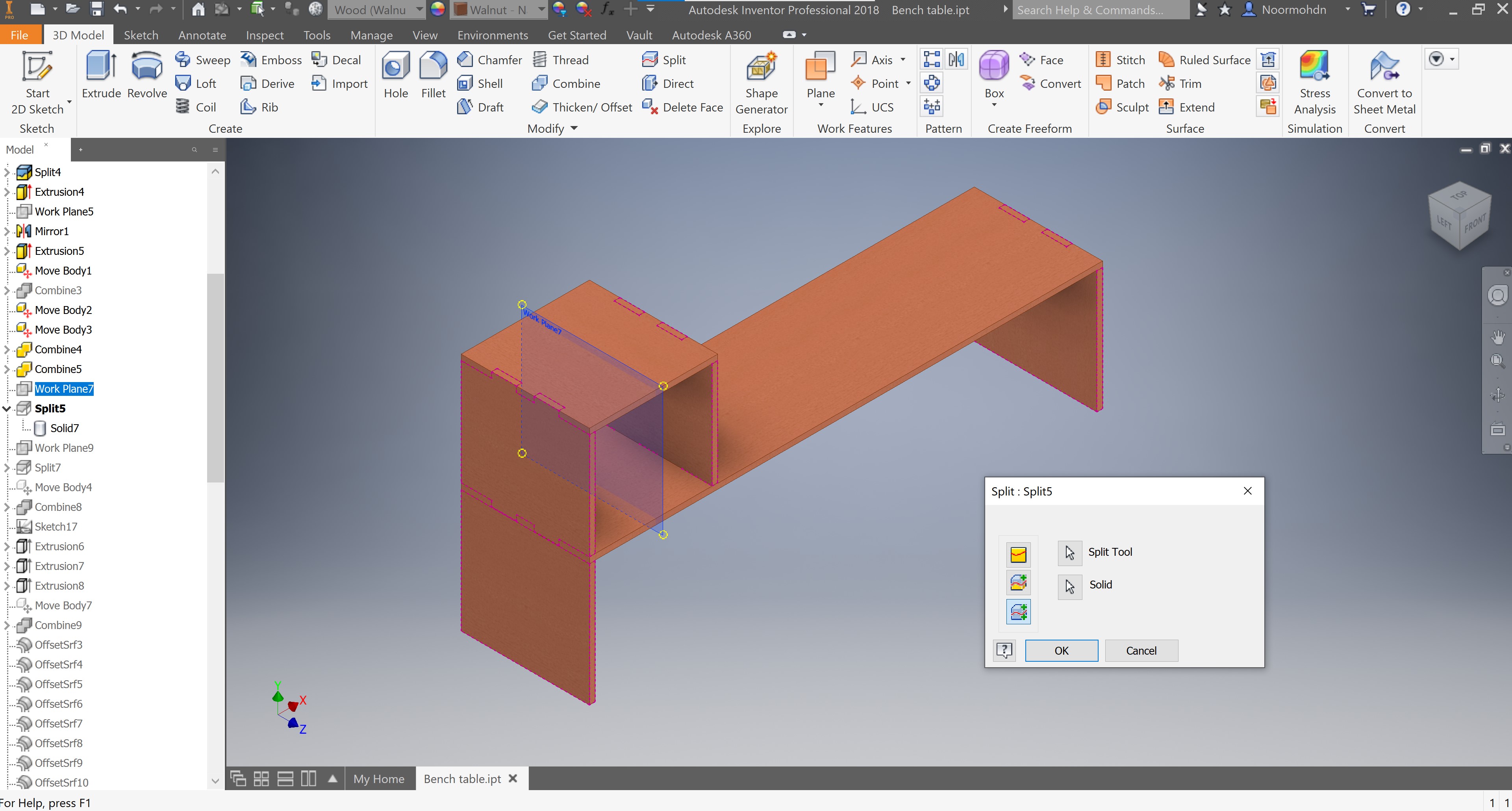
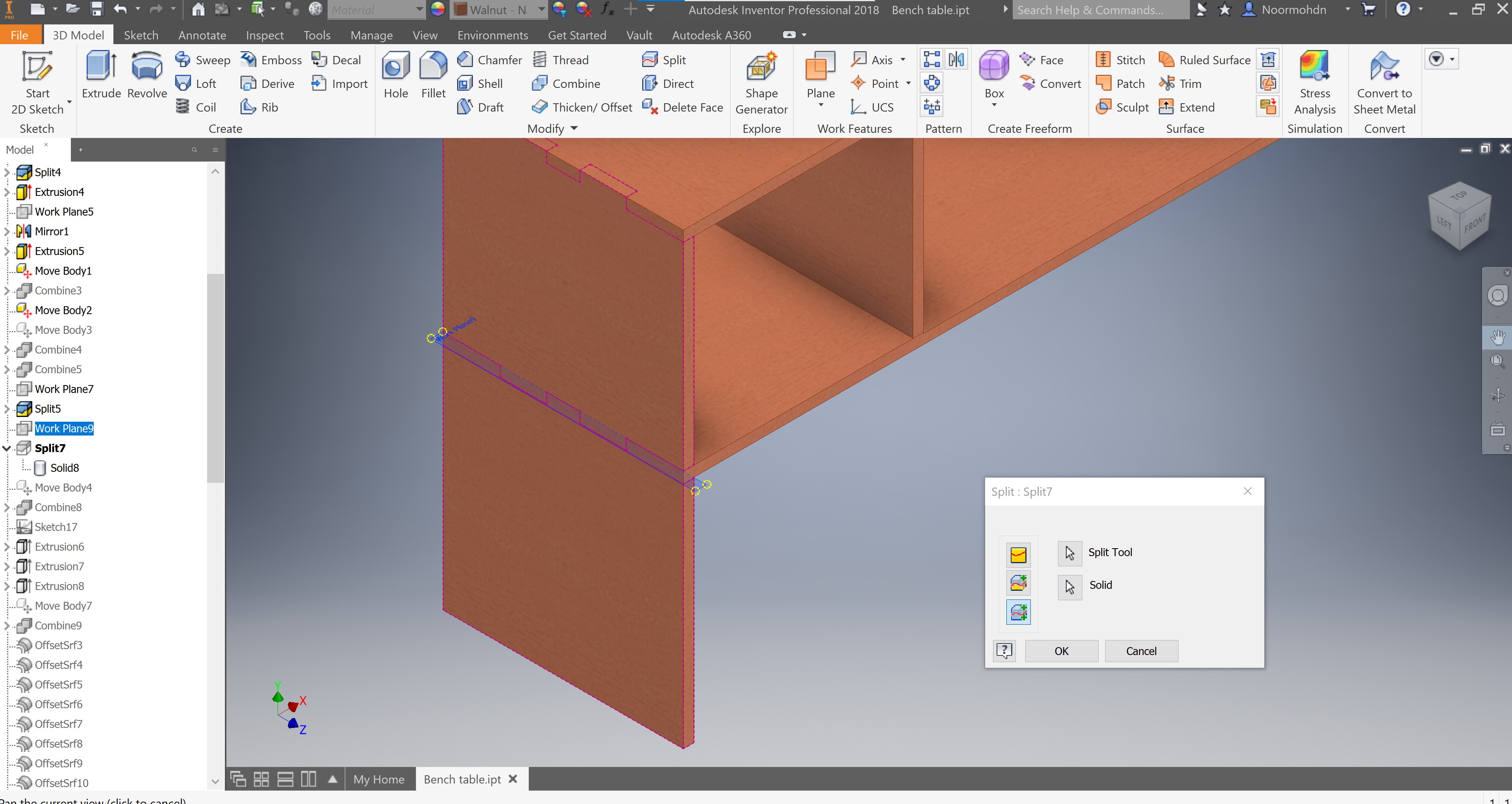
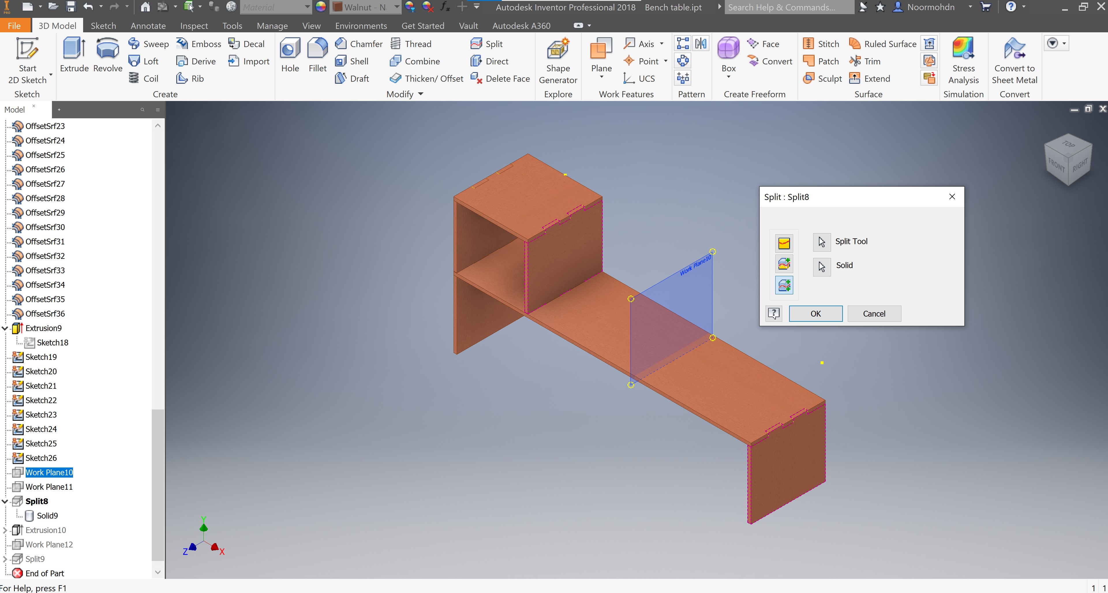
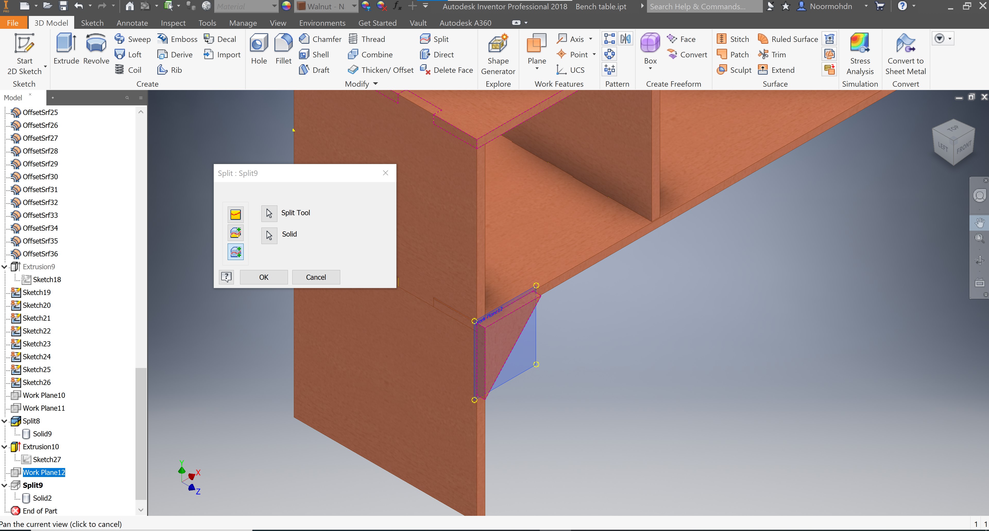
After completing my 3D design as a one part. I have split each part into new solids to perform my design using the following tool shown in the picture. 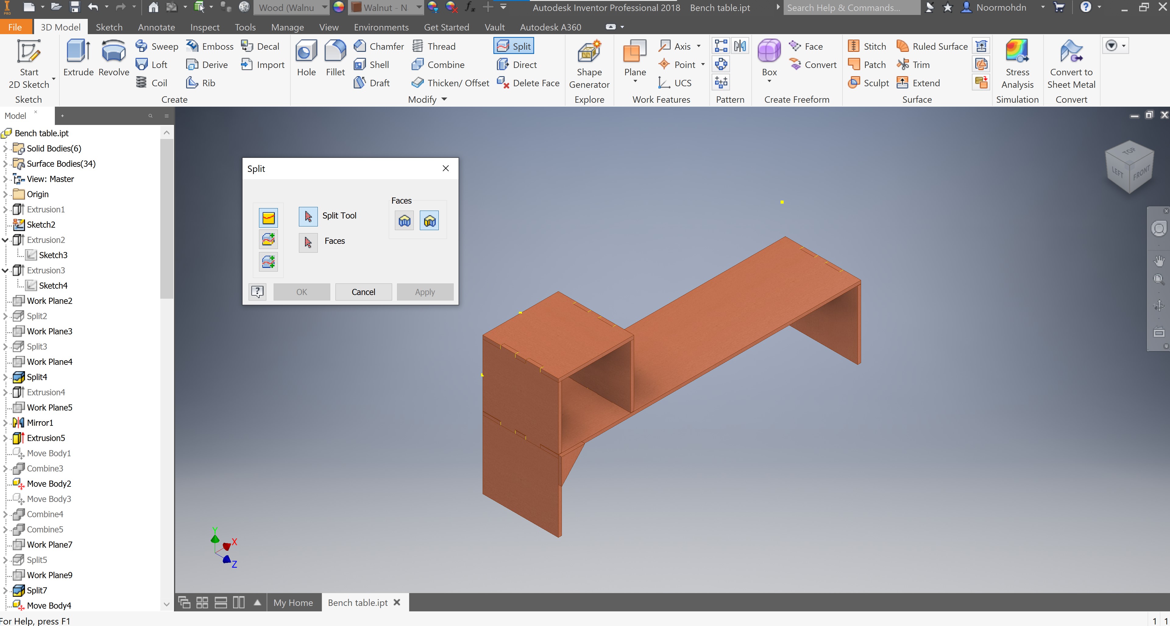 By selecting the split tool and the solid desired to do the action with, the tool will do its work by splitting the two solids. the split tool I used is having plans between the two solids.
Design Parts
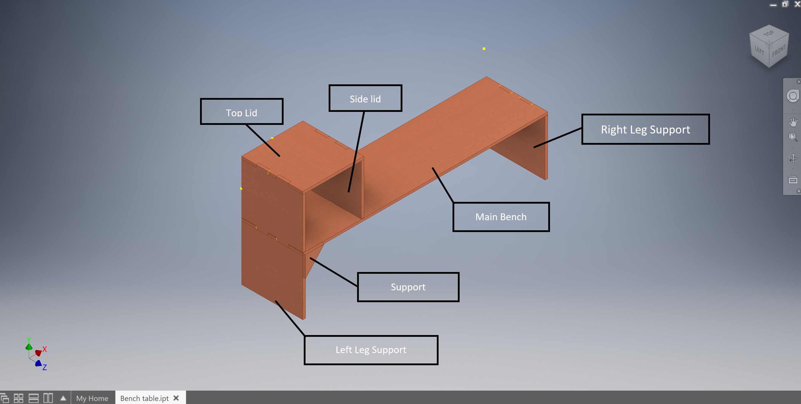
My design contains of several parts, the main part of my design is the main bench were all the parts is connected to. The second part is the right leg that support the main bench. The other support is a longer one, which is the left leg support showed in the following picture. One section of it is connected to the box on the bench. This part was divided by two parts, but I have changed the layout of the two section and made it as one part to ease the cutting and assembly process of the parts. Lastly, the other solids the top lid, and the side lid are the complete part of the box. All the parts are shown in the following picture. The design parts process is an on going process through my whole design.
As an extra support I have developed a triangle shaped support to make sure that the legs will not bend when applying load to it. These supports will be mounted on the four edges of my design.
Third
I have drawn each specific joint which will be beneficial to the selected parts at each certain location. To choose them there are many joints types as you can see in the following figure.
 I have used the Box joints and the biscuit joints in some locations as shown in the following photo.
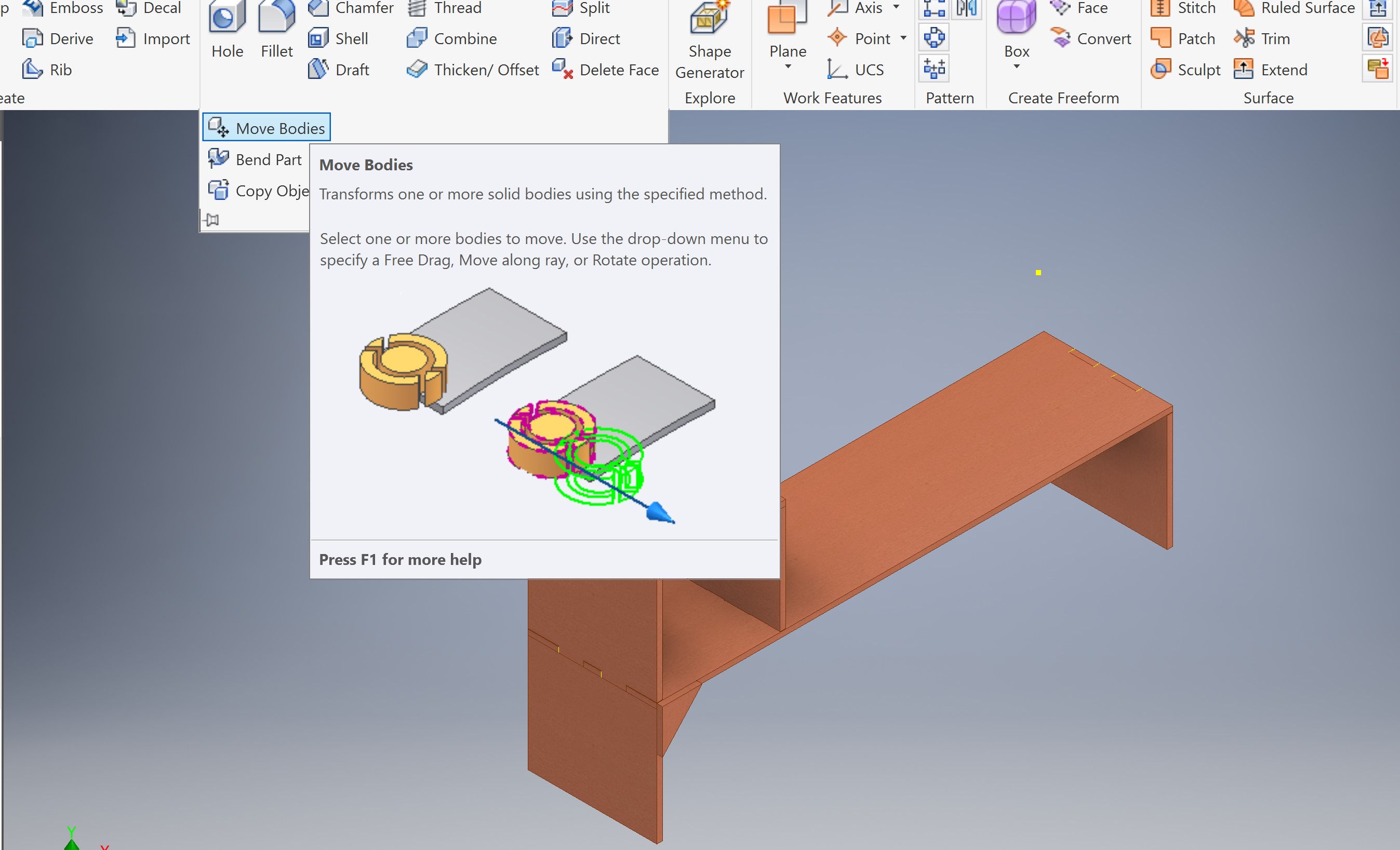
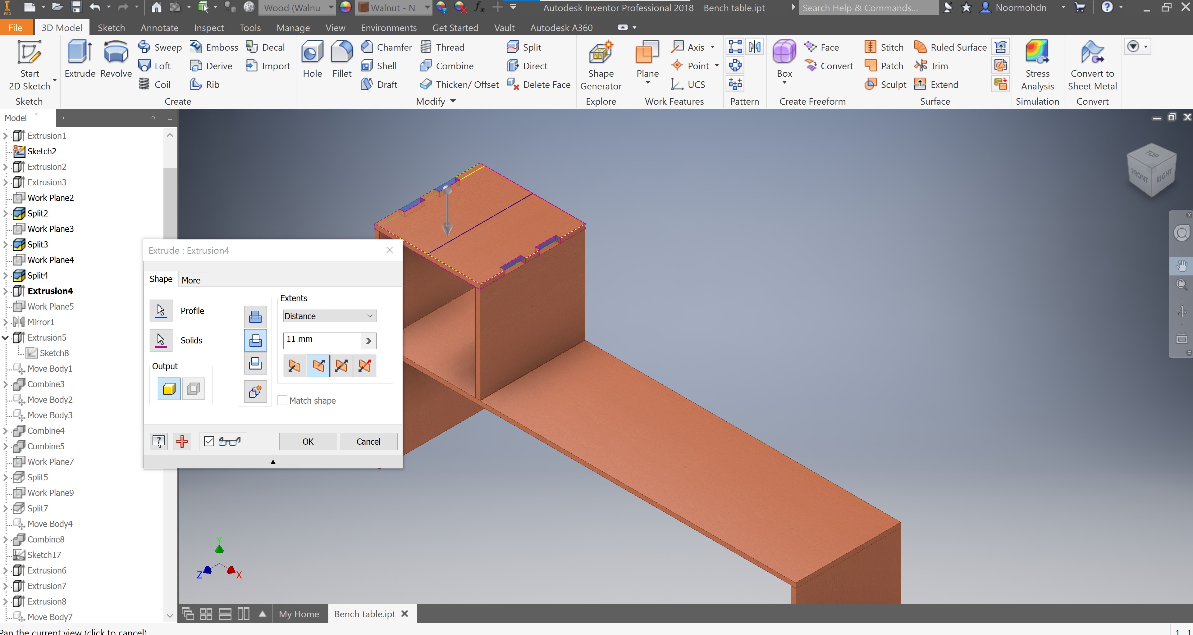
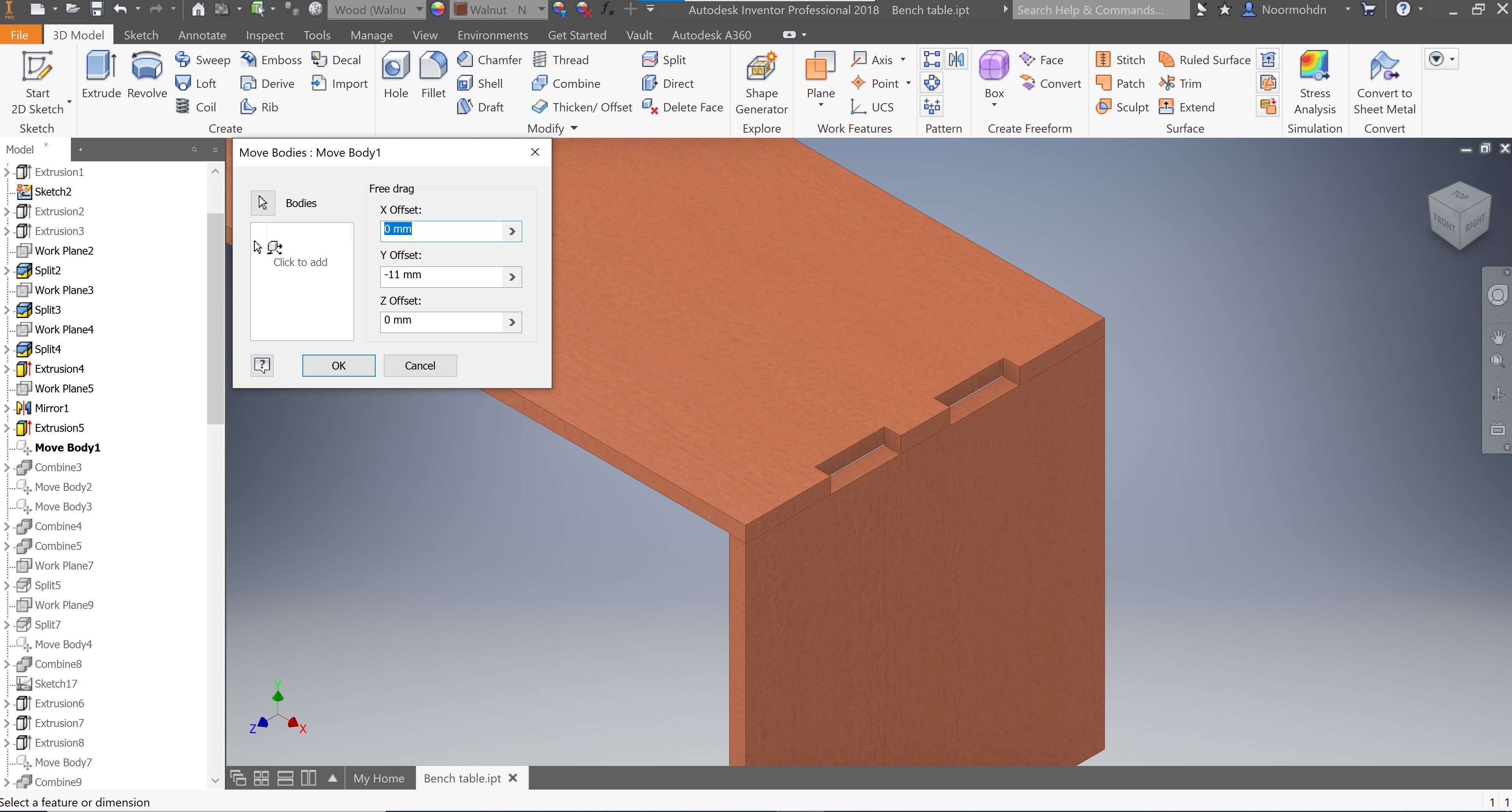
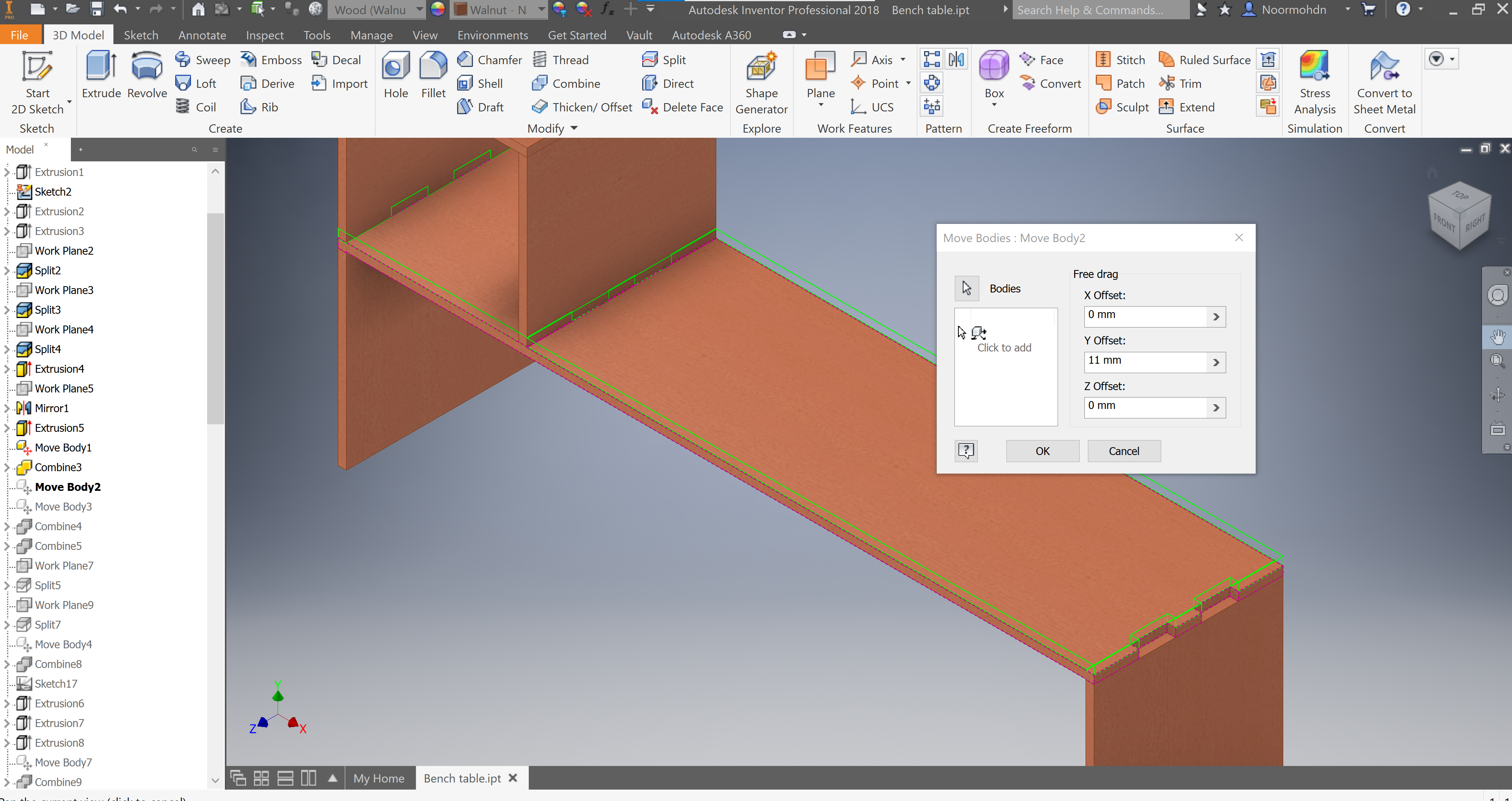
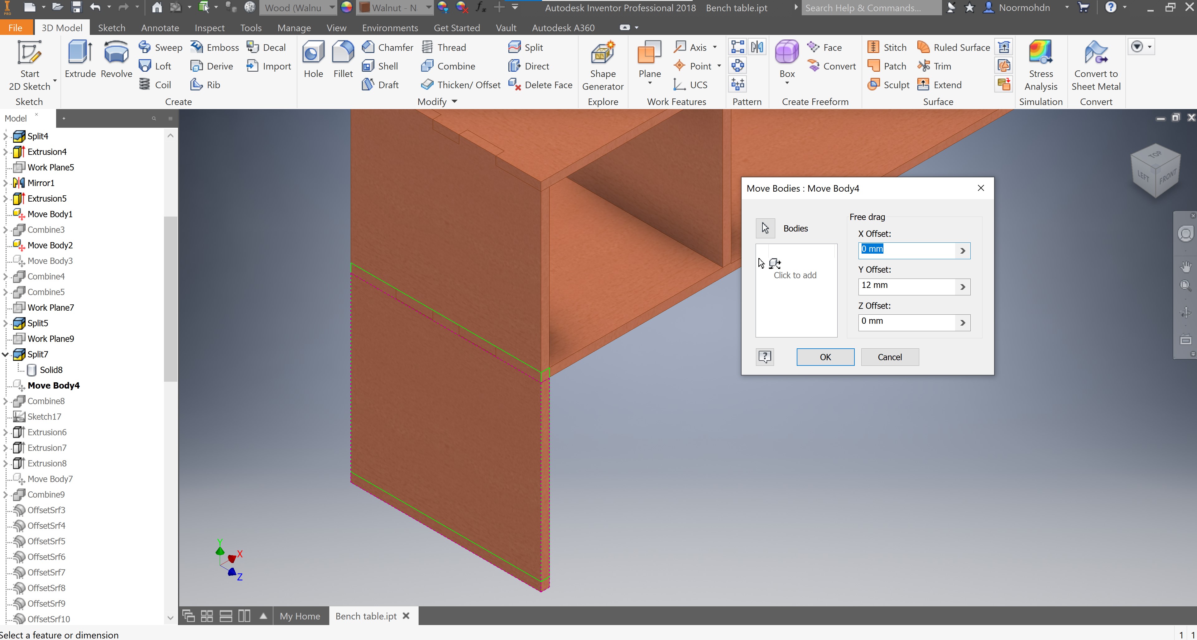
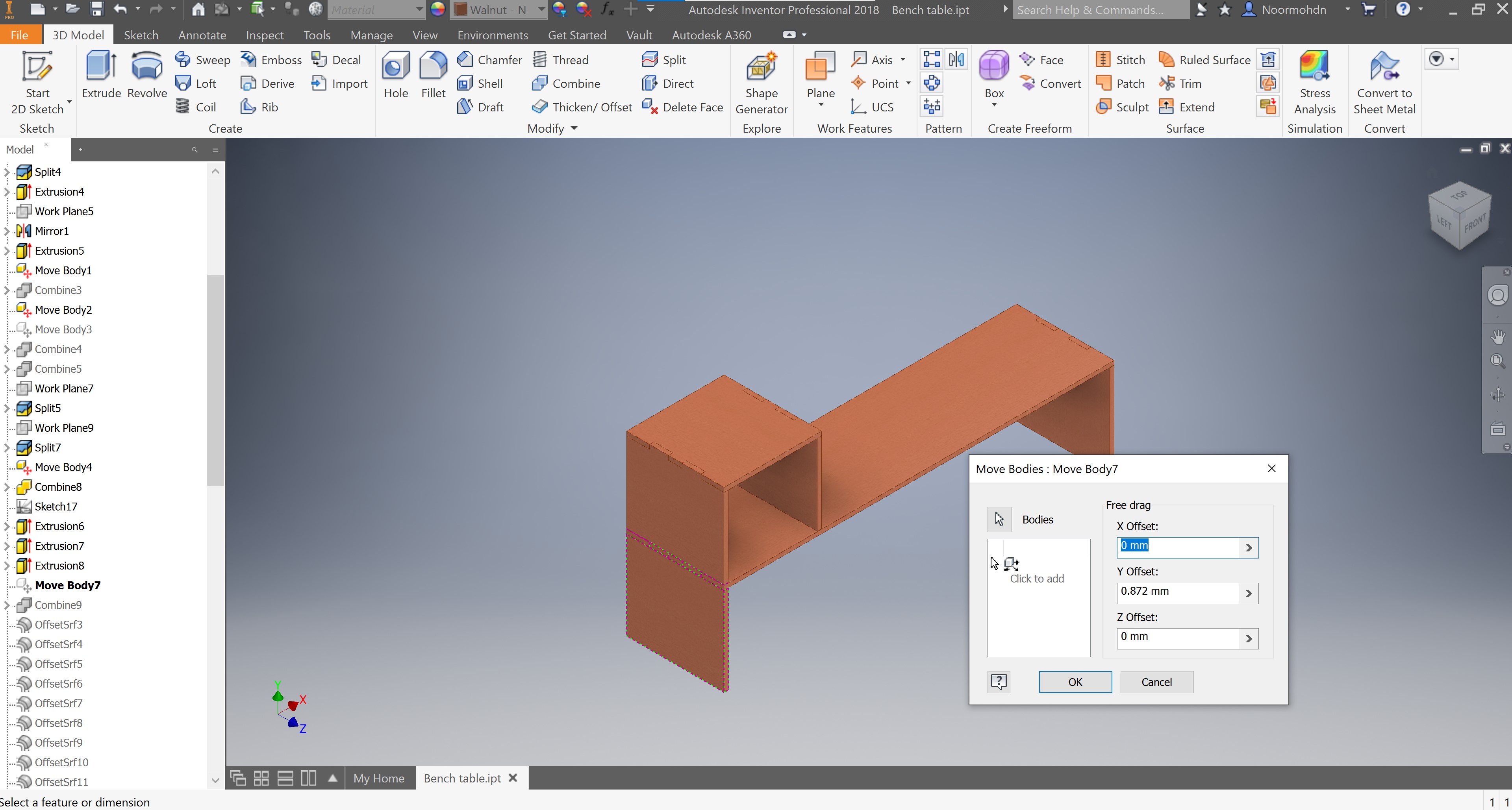
 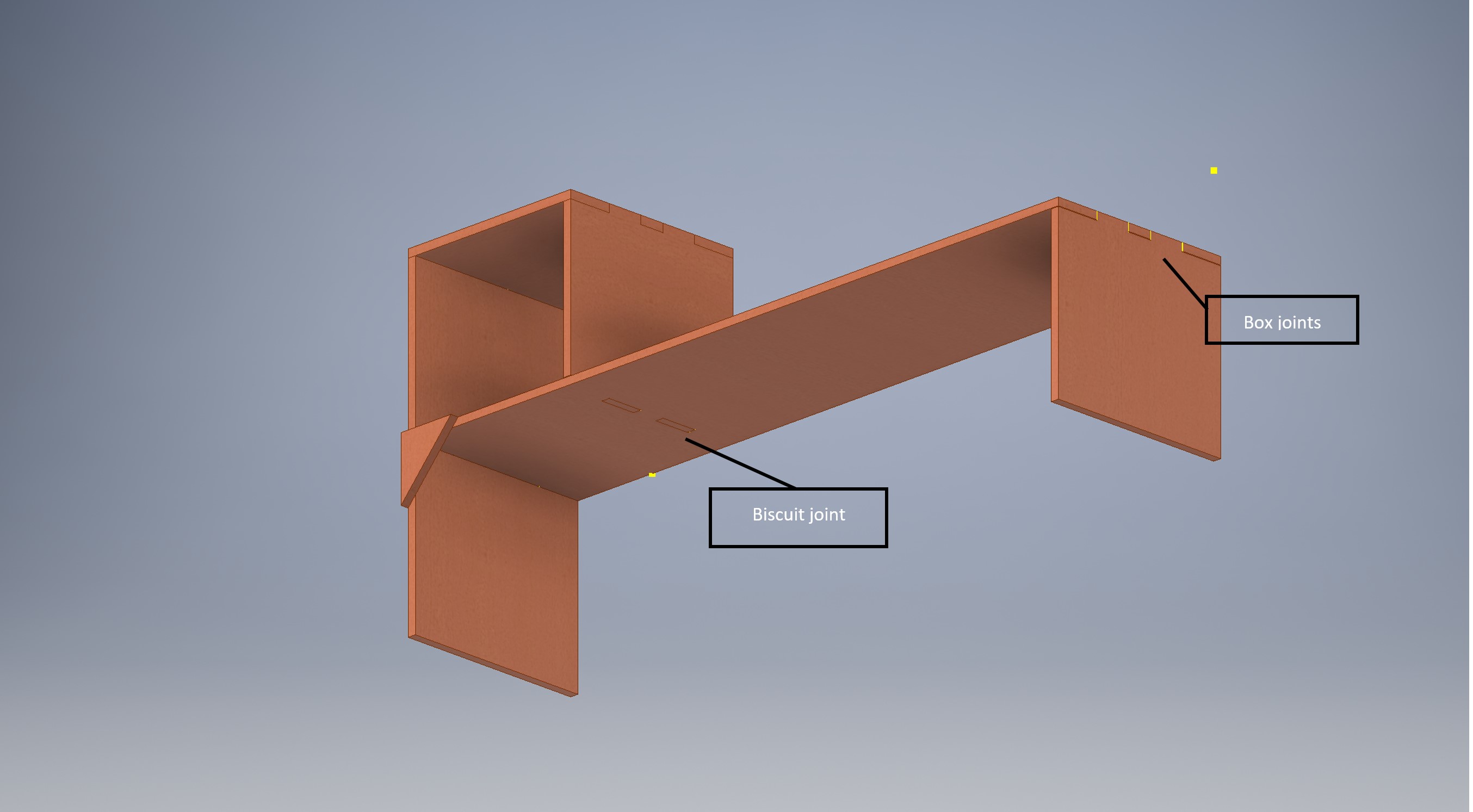 The joints drawings were applied on each part of the drawing. To perform this action we have used the move bodies tool in modify section, so we can move the bodies that we want to join together. I have moved the bodies to a distance of 11mm which is the thickness of our plywood.
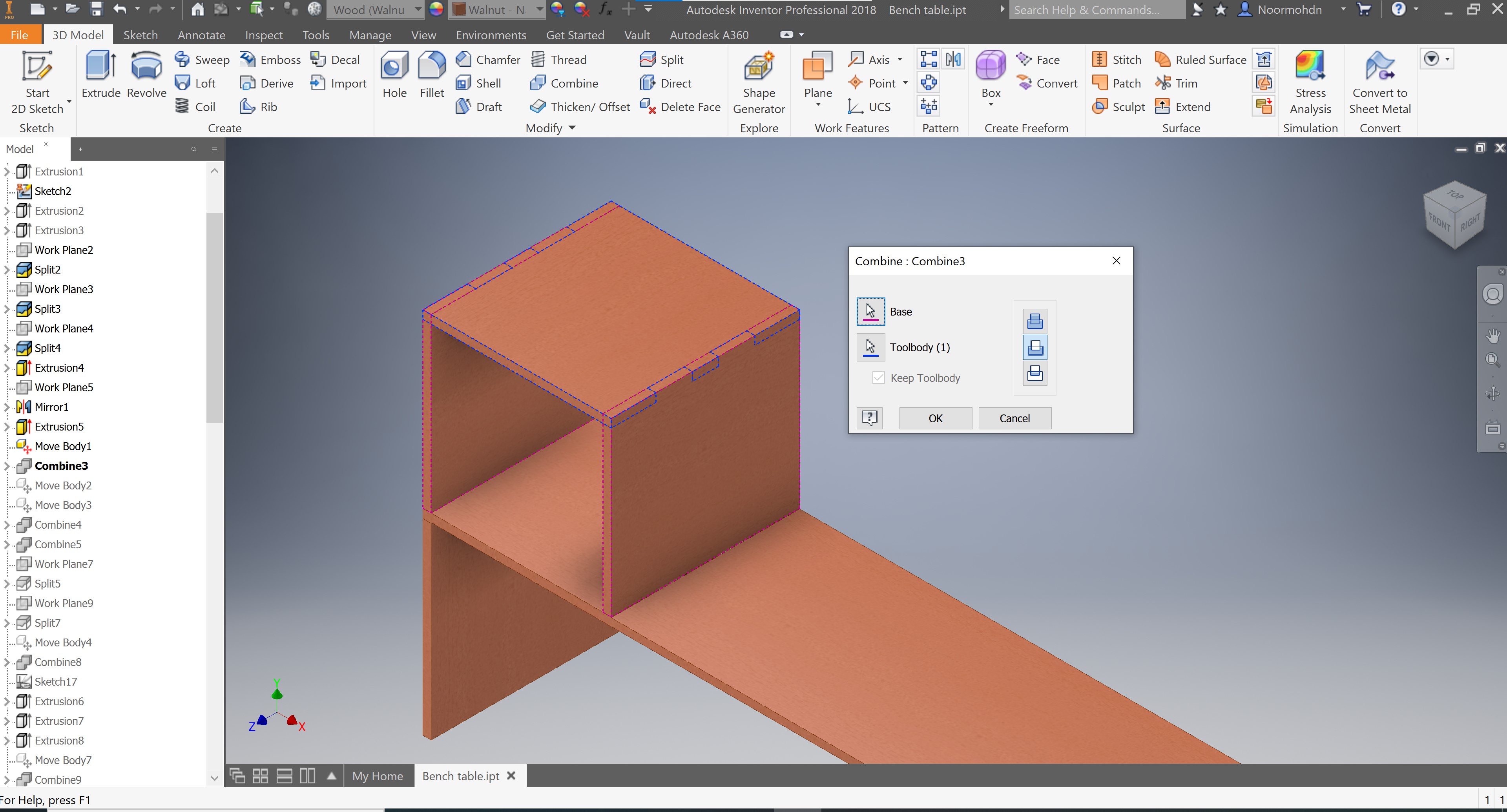
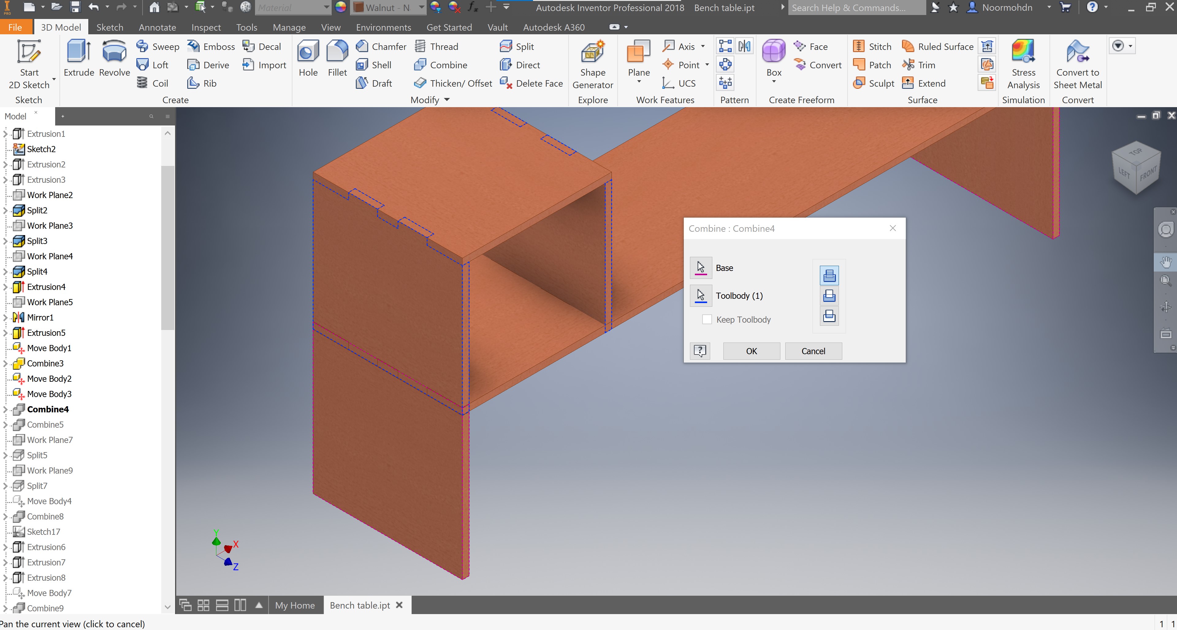
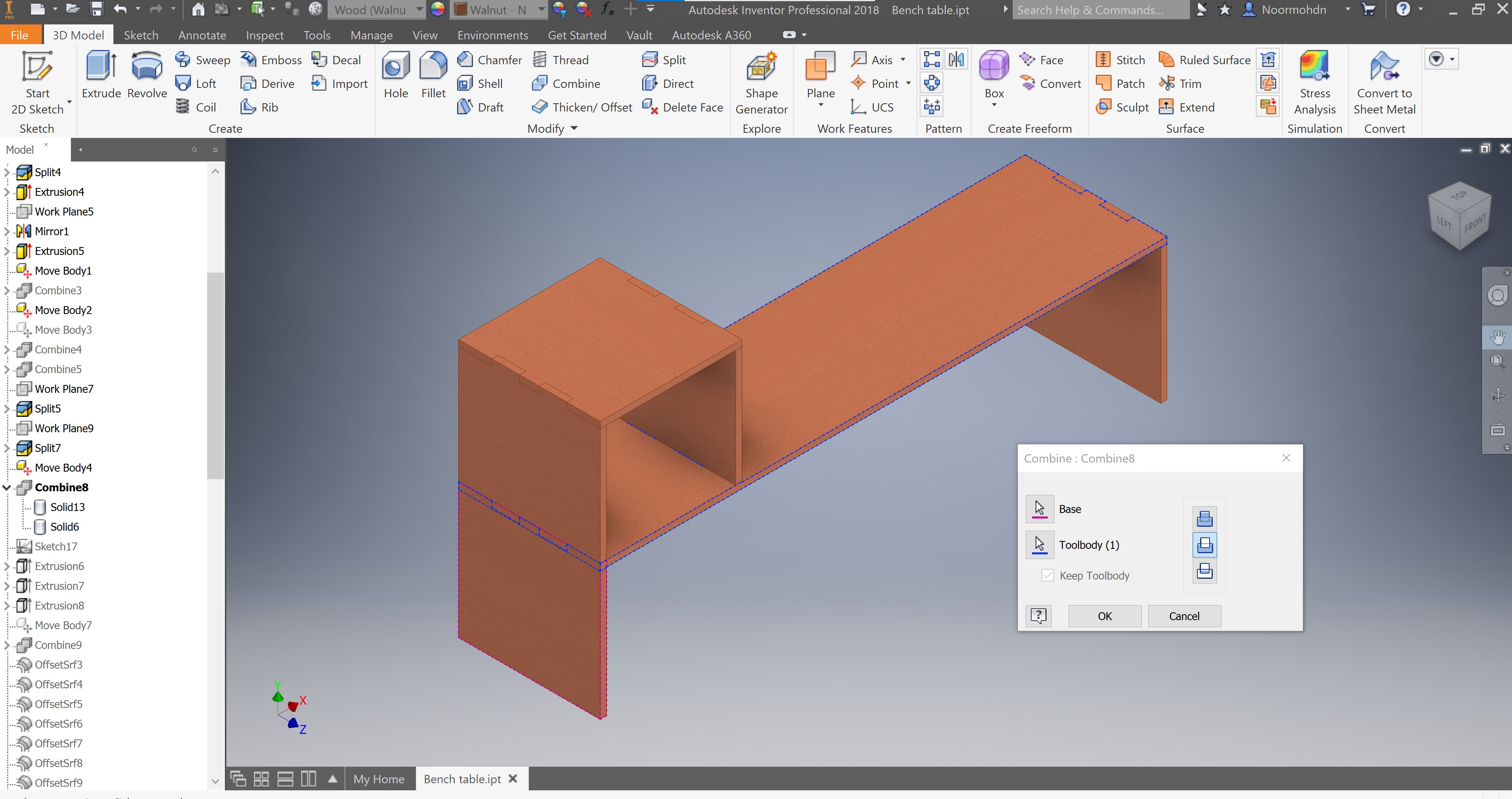
 After moving the bodies we combine the bodies and perform an action that called cut as what the curser is pointing on the following picture, this action will cut the other part that does not have the joint drawing in and will have a replicate drawing to the joints on the first part. this action also performed using some of offset planes on some surfaces.
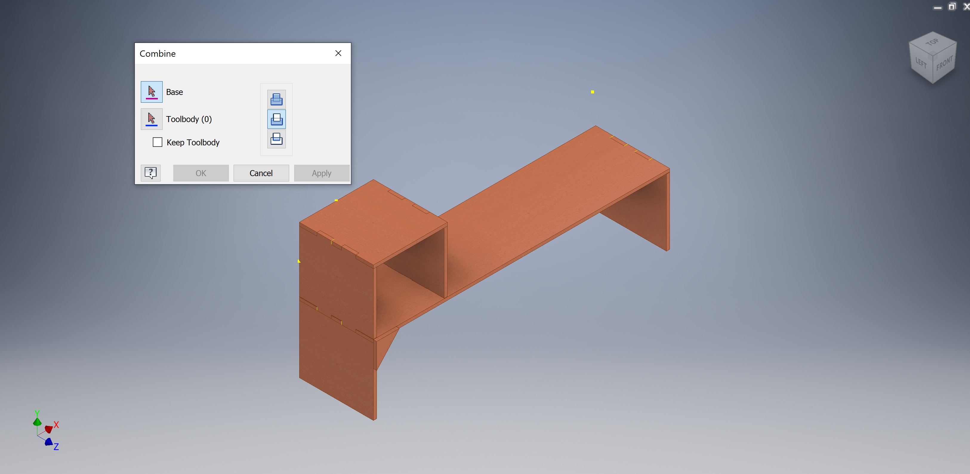
Forth
After completing the 3D design of my bench table I have converted each solid part mention previously into an idw. (drawing) template, this template is further converted into a pdf file format to be generated on the CNC program, the file type should be DXF.
Details
Note this section is ab addition to the prior section. The steps followed will be discussing in details he steps done to do the bench table. The documentation on this section will be a bit lengthy due to some design difficulties. Hence, you do not need to follow them because some of them were making up and editing a previous mistake made to the design ]m all will be discussed on the following series steps.
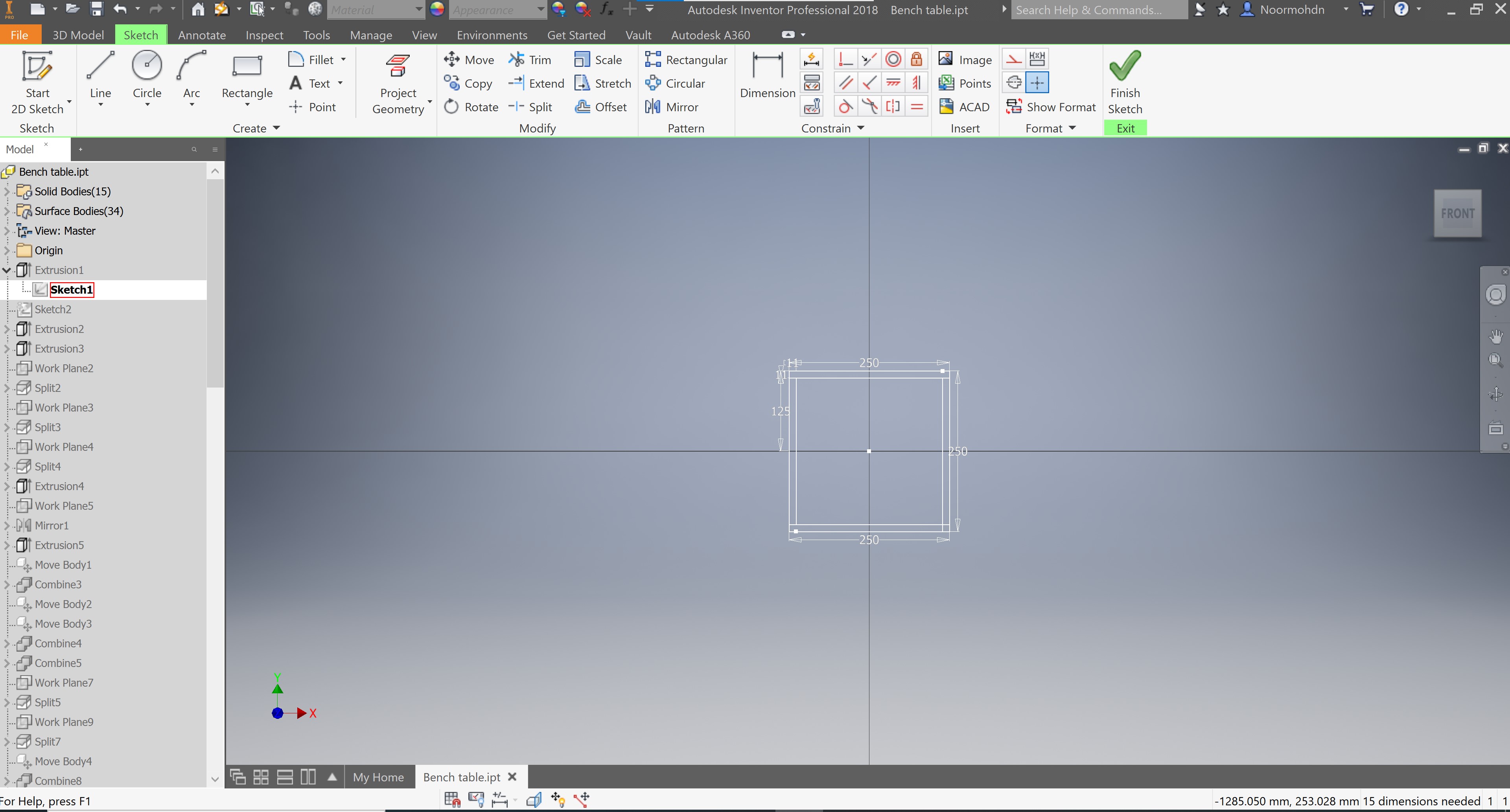
The following photo shows the first sketch made in order to do my bench table design. The sketch is for the box linked to the bench tale body, the box is used to put whatever object is suitable to use.
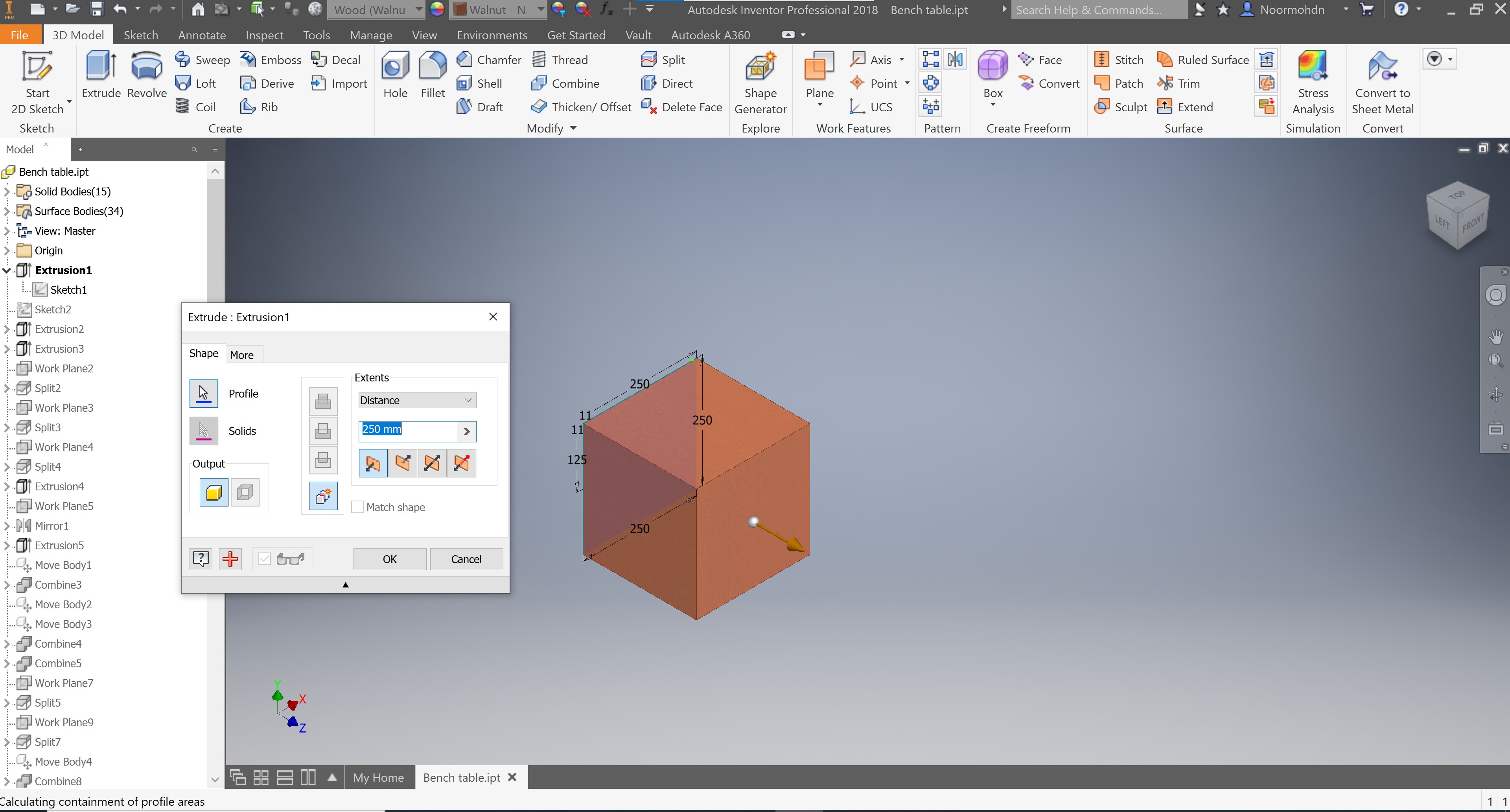
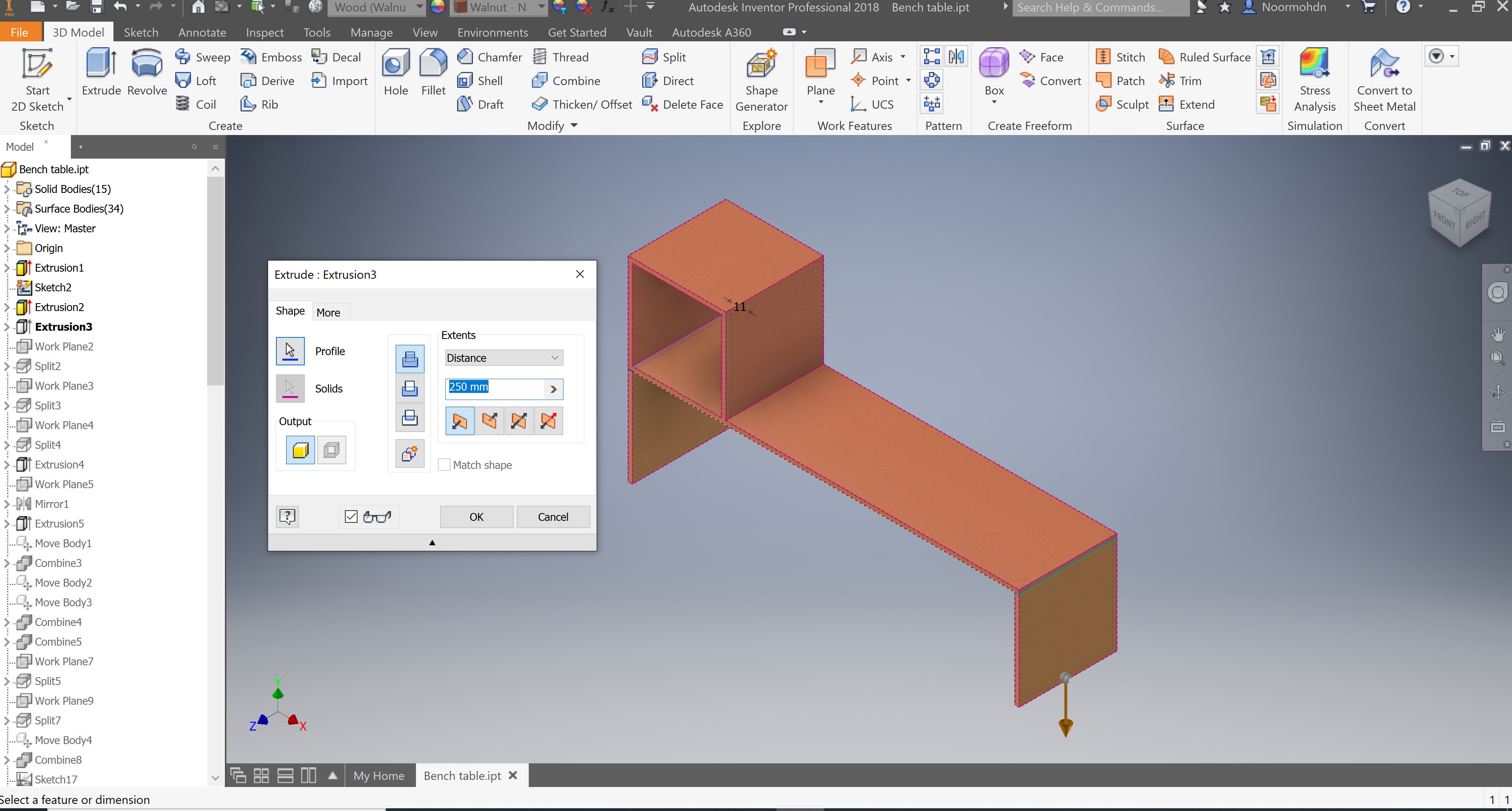
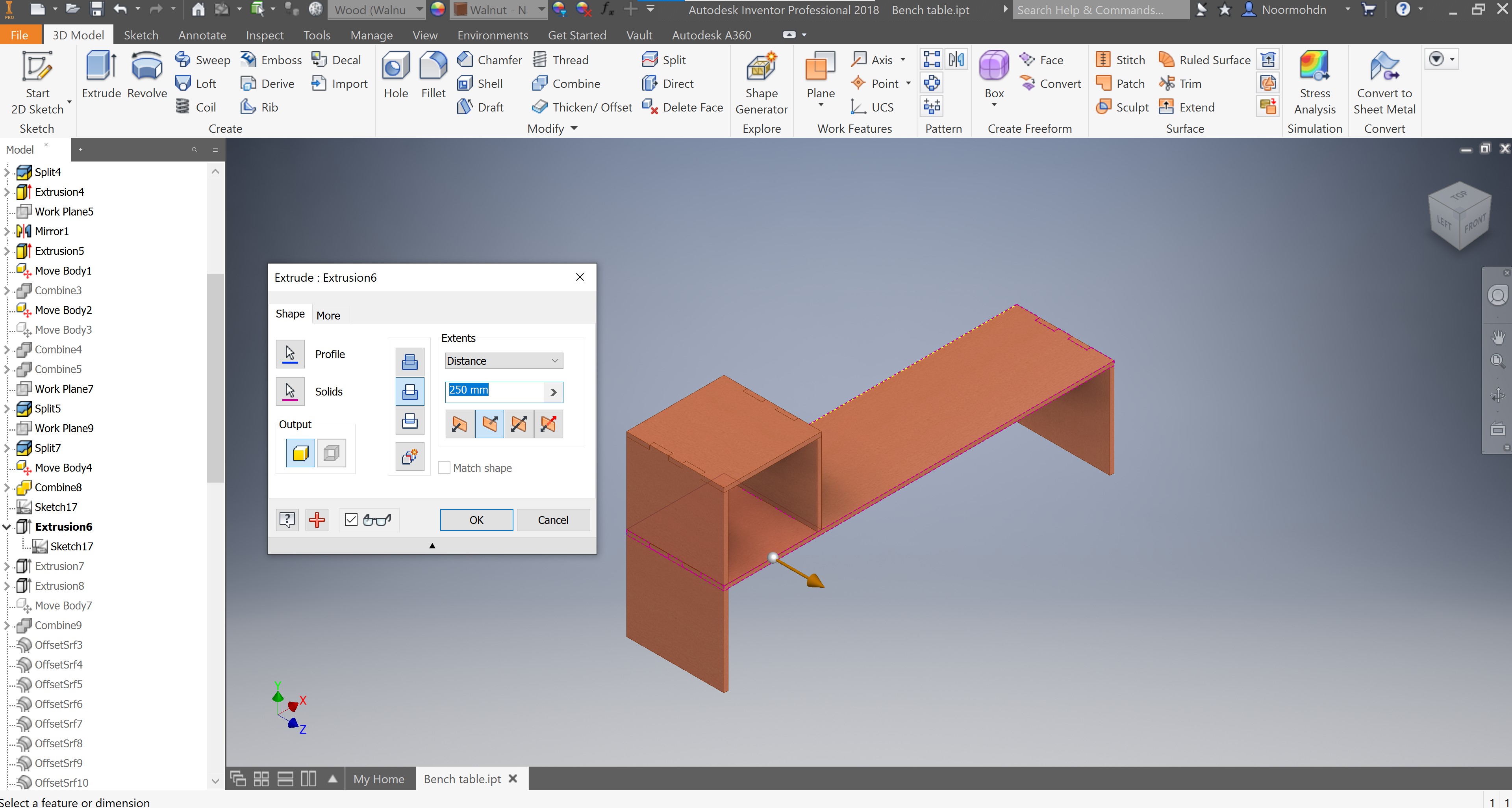
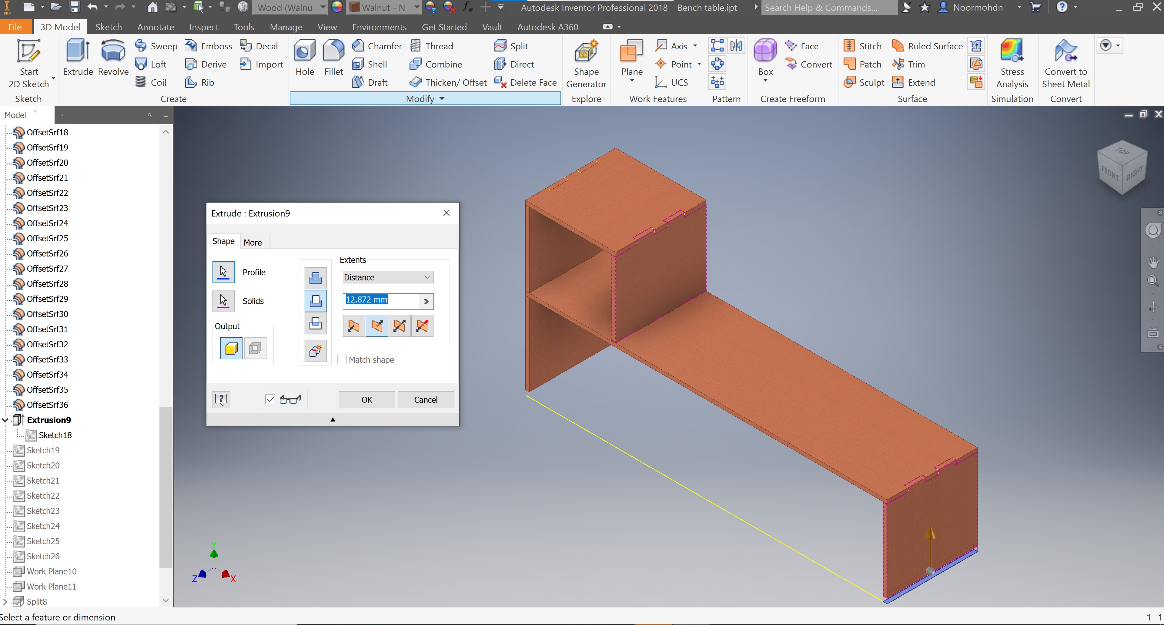
After having the first sketch I made an extrusion action to the box to has it desired shape, the tab shows the extrude dimension made.
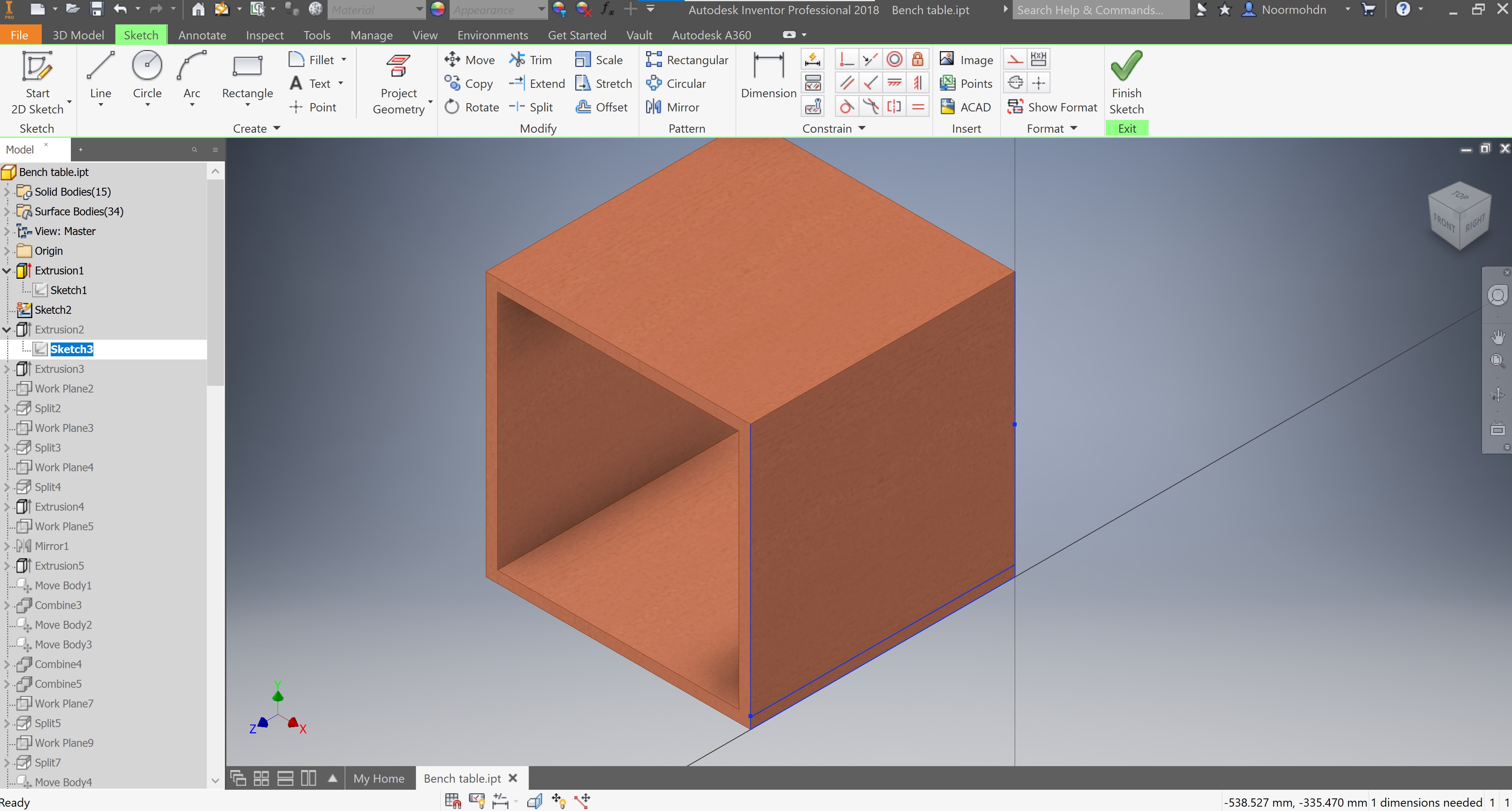
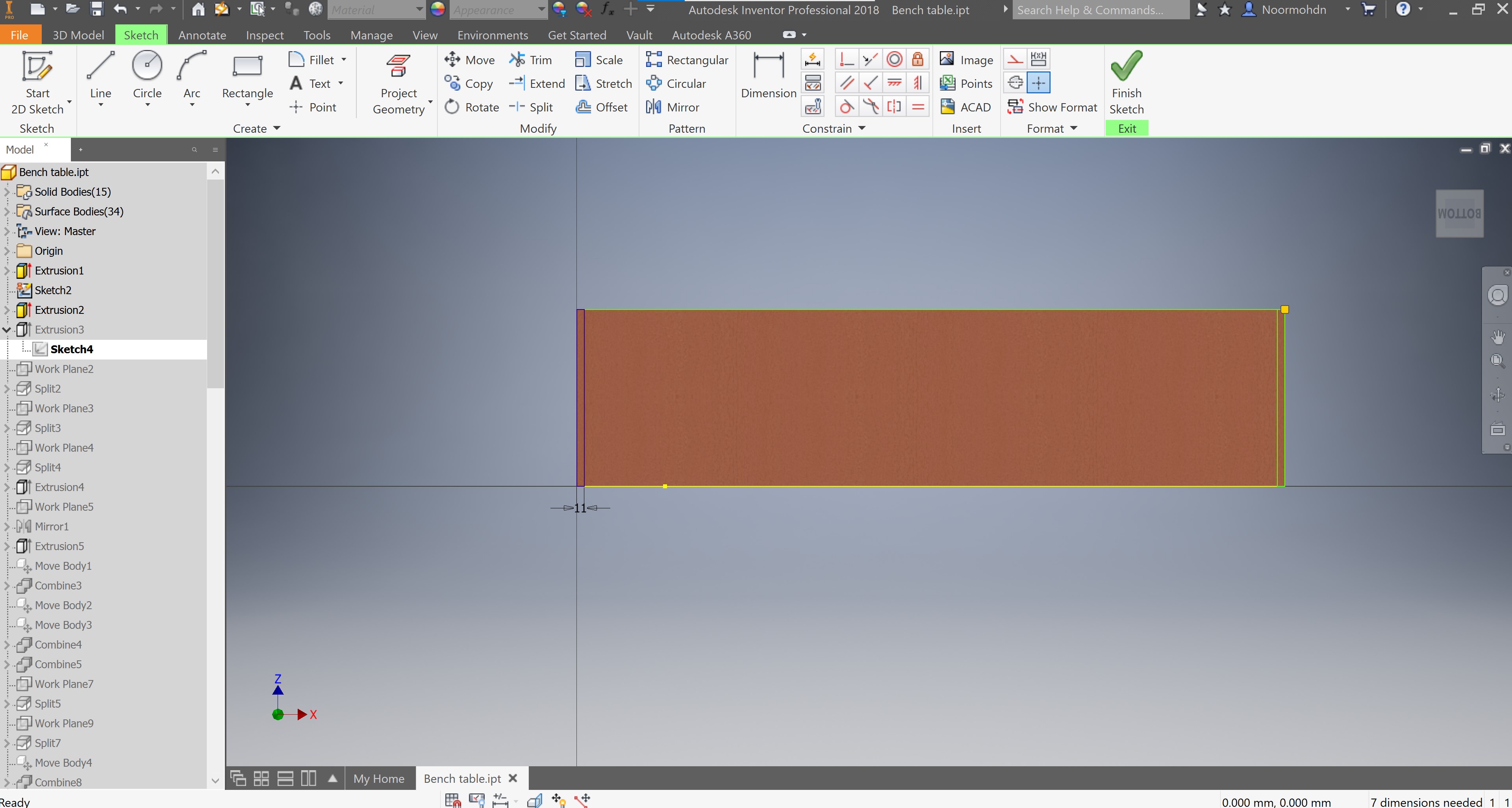
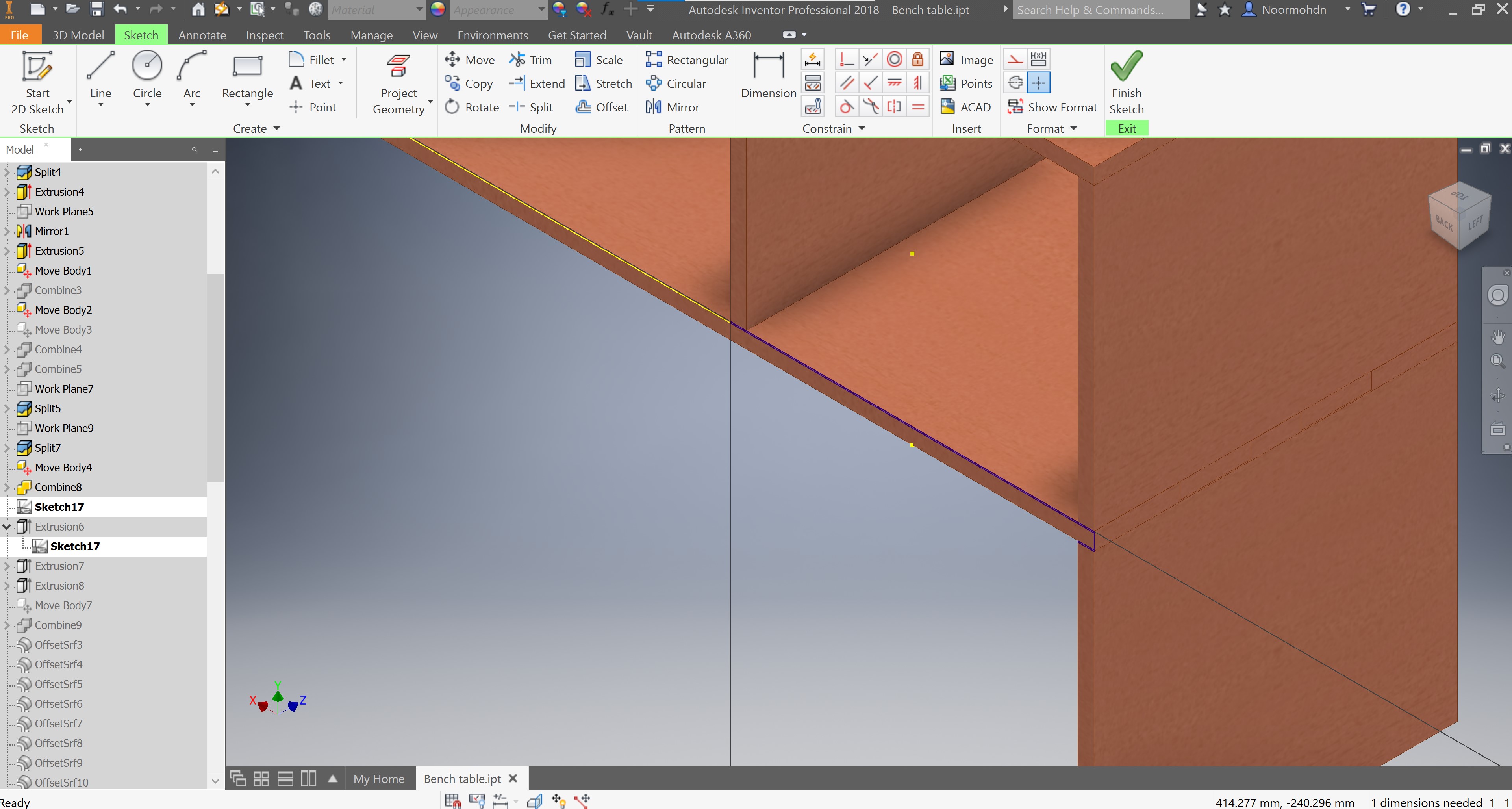
After completing the first extrude, I made another sketch on one of the box sides in order to the bench slab required. Which is the section where the people can set and use often. The following photo shows the second sketch made in blue lines.
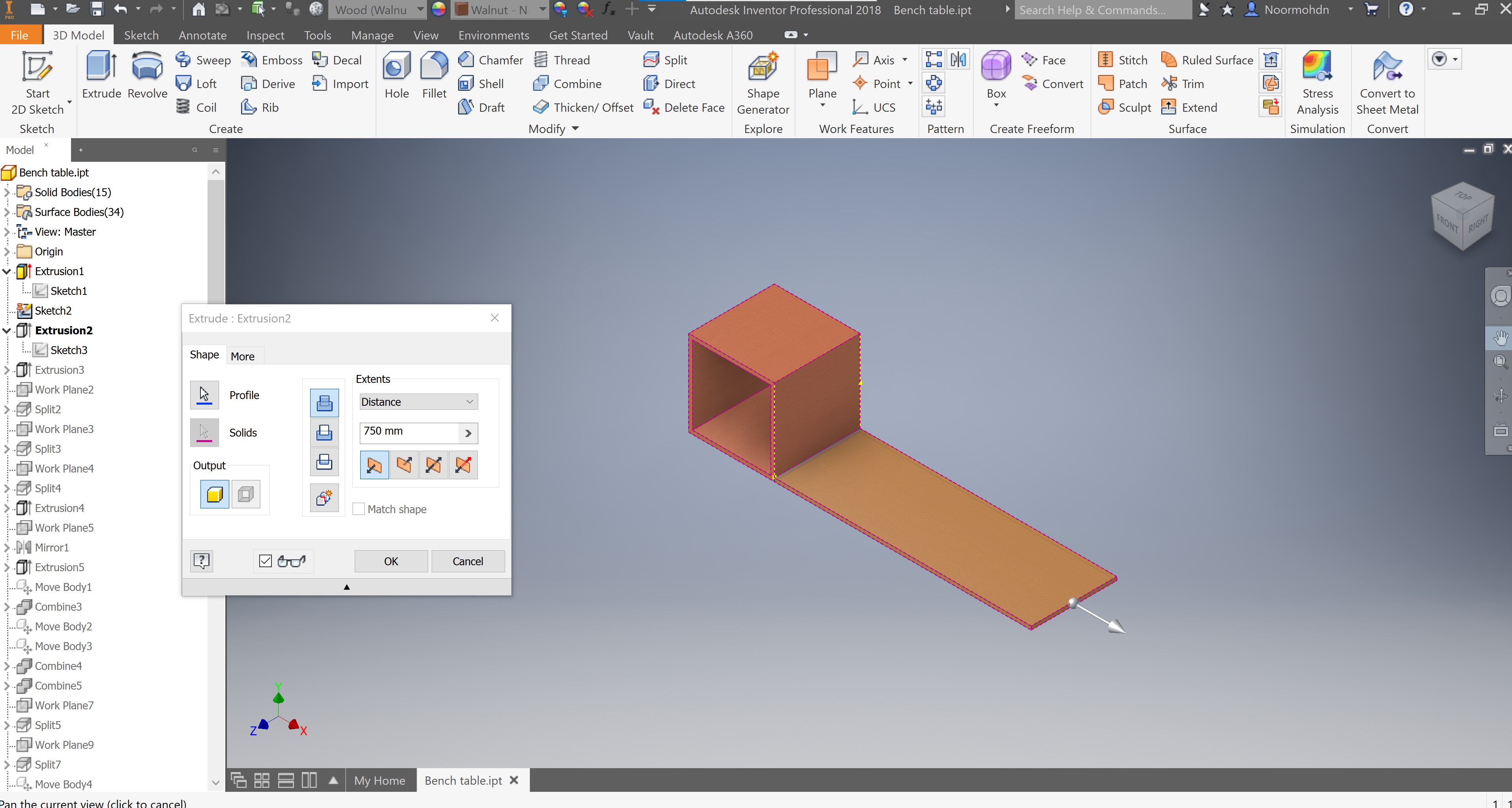
After having the second sketch, an extrude was made in order to do the desired length of the bench slab as stated on the pop up tab.
Next, I made a sketch under the bench slab in order to do the bench table legs.
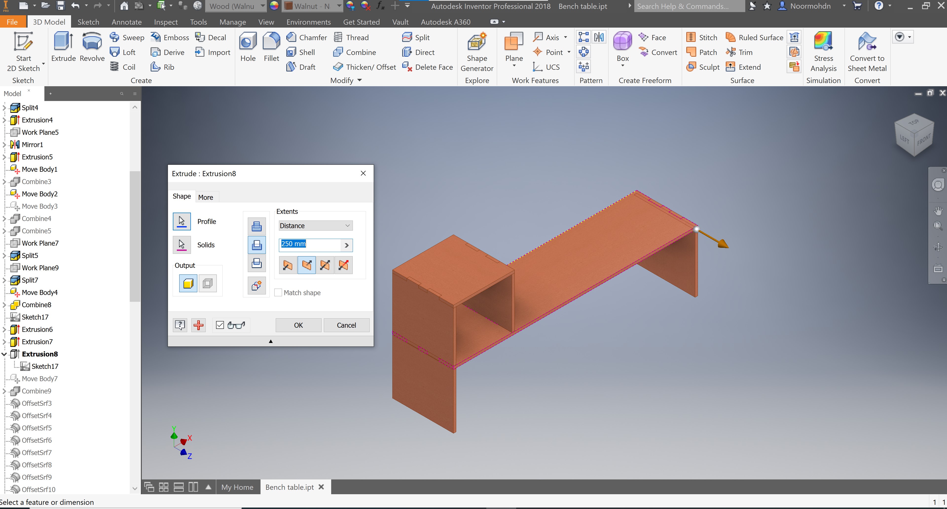
After having the sketch I made the desired extrusion action to the length of the bench table legs.
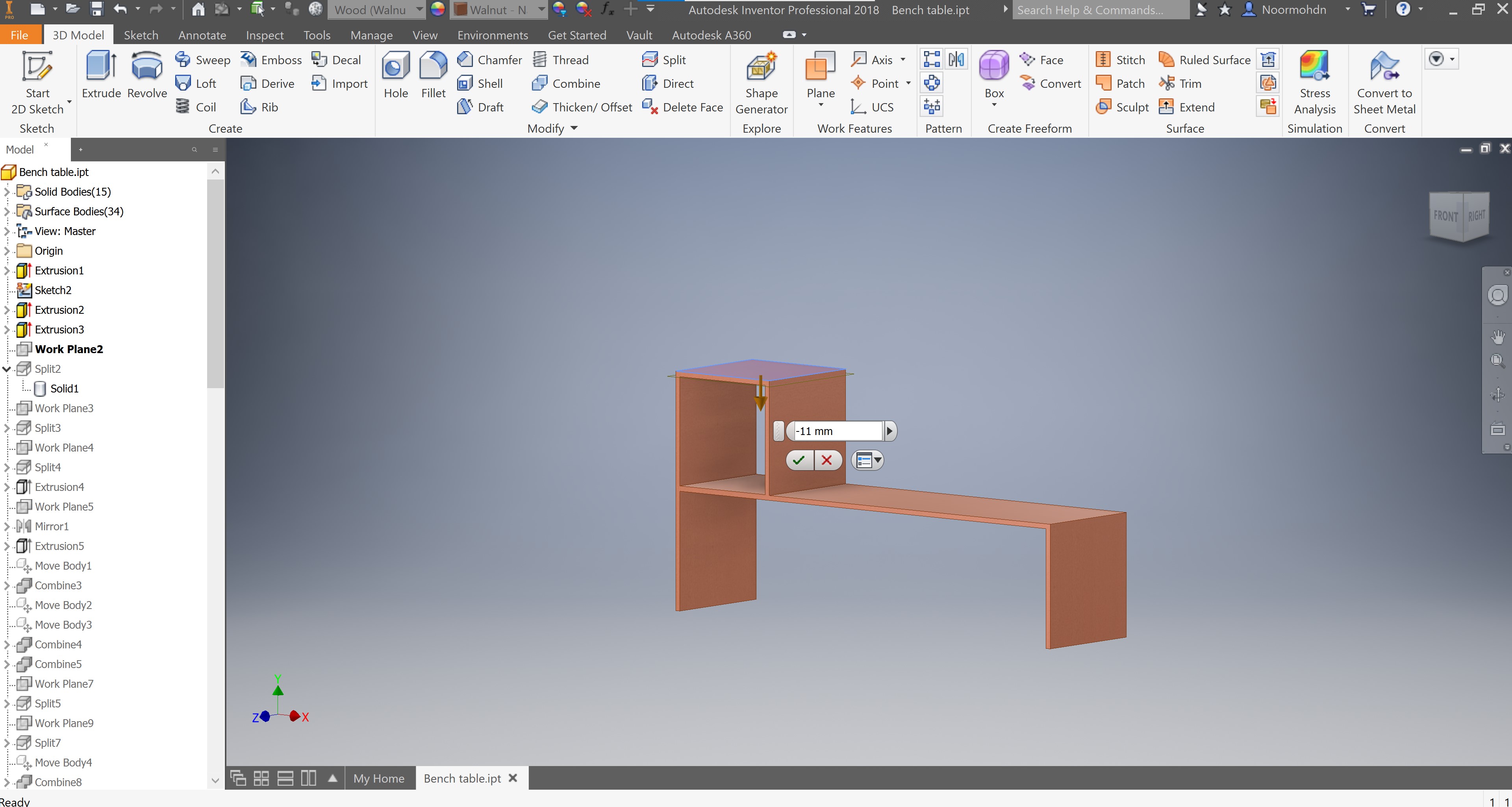
I made a work plane from the top surface of the box to -11mm down the surface in order to split the top side of the box to both sides of the box. The 11mm is the plywood thickness.
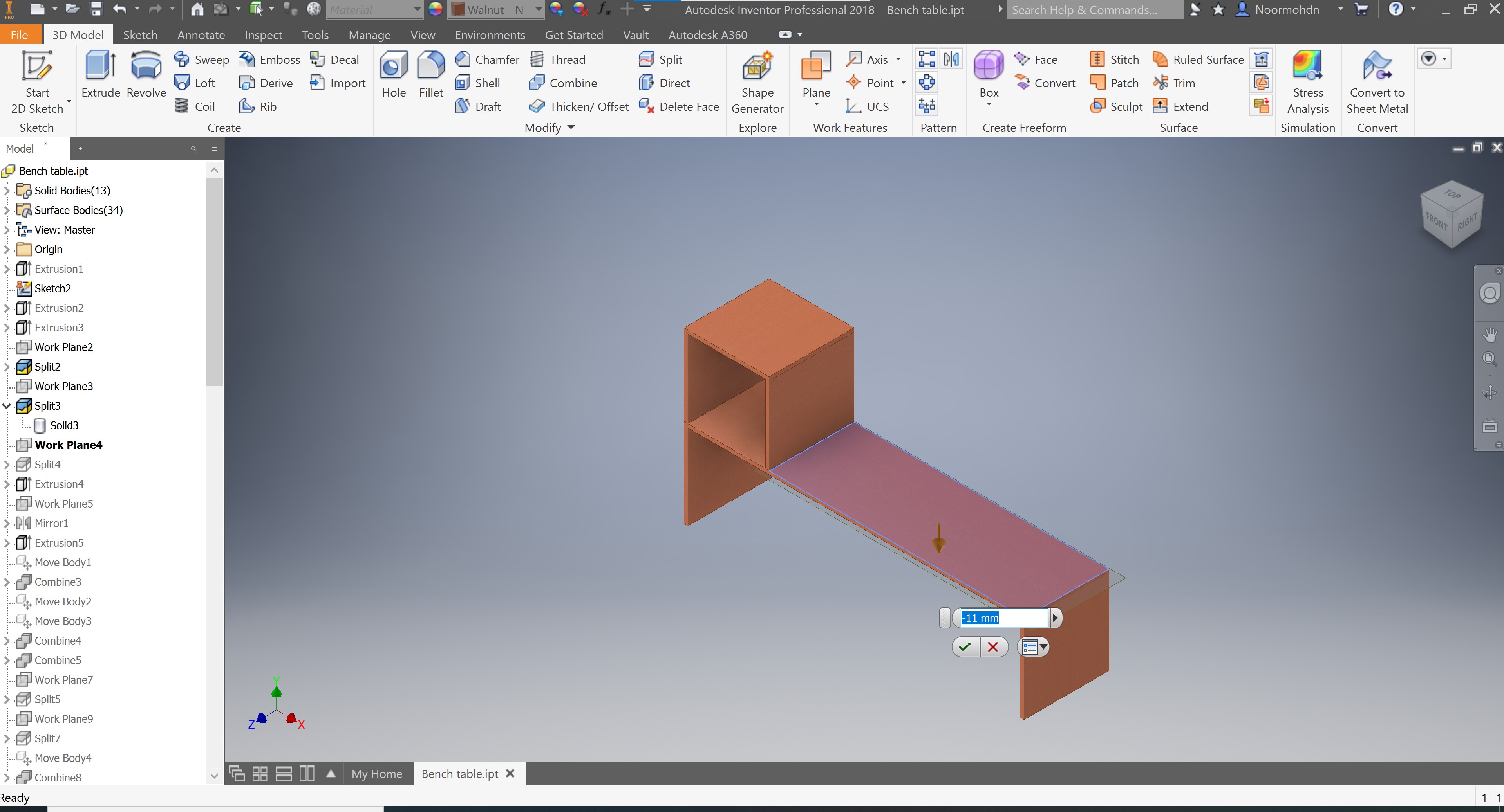
The same process is made to the bench slab in order to separate it from the box section as it is an individual piece. A work-plane is made in order to take it as a split tool to perform the split operation for both the above and this section step.

Another split tool is made to split the bench table slab. As this step on the following steps done was a mistake so I hade to make it again as a one piece better than two separated. This will be discussed on the following steps.
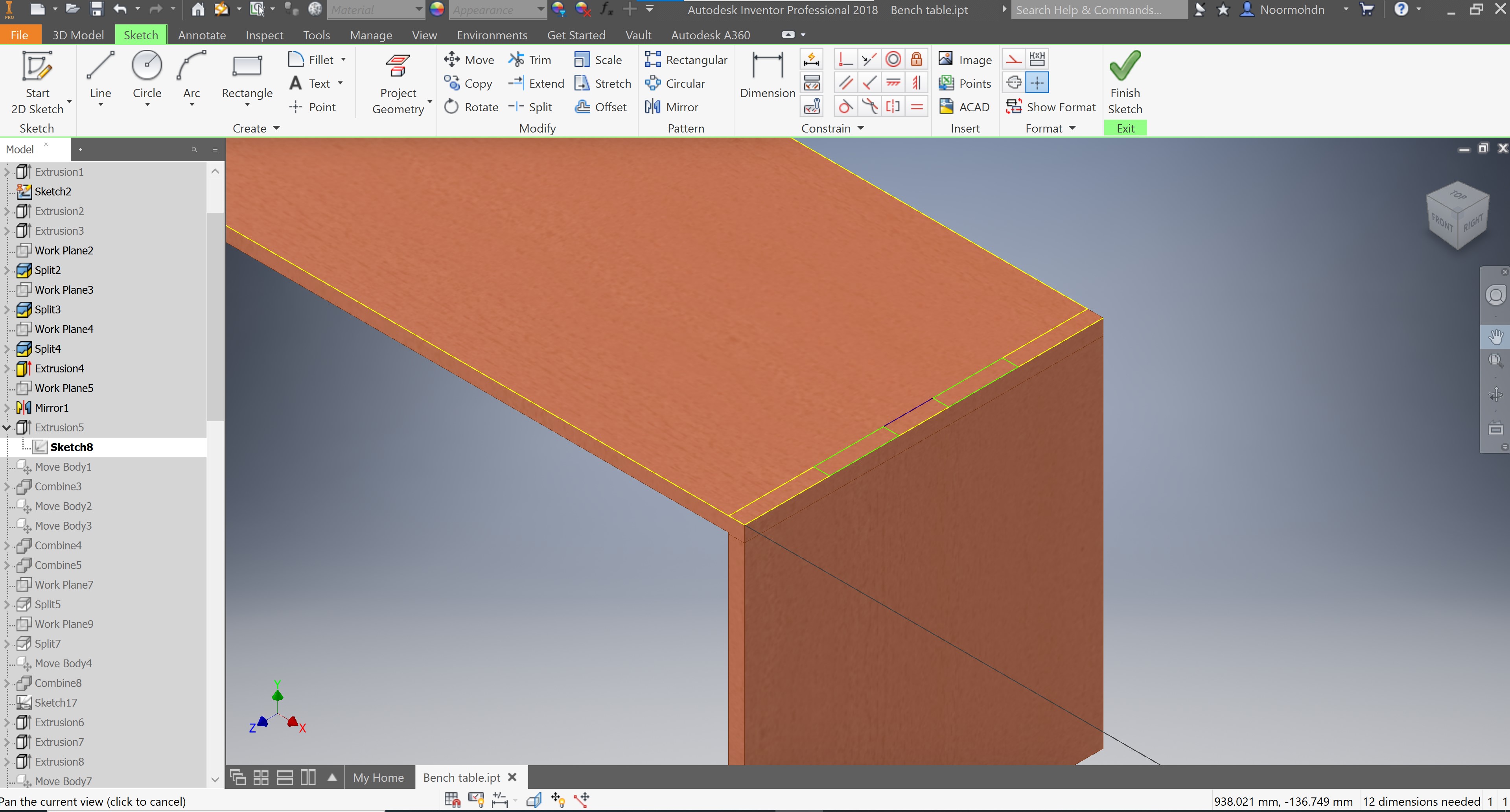
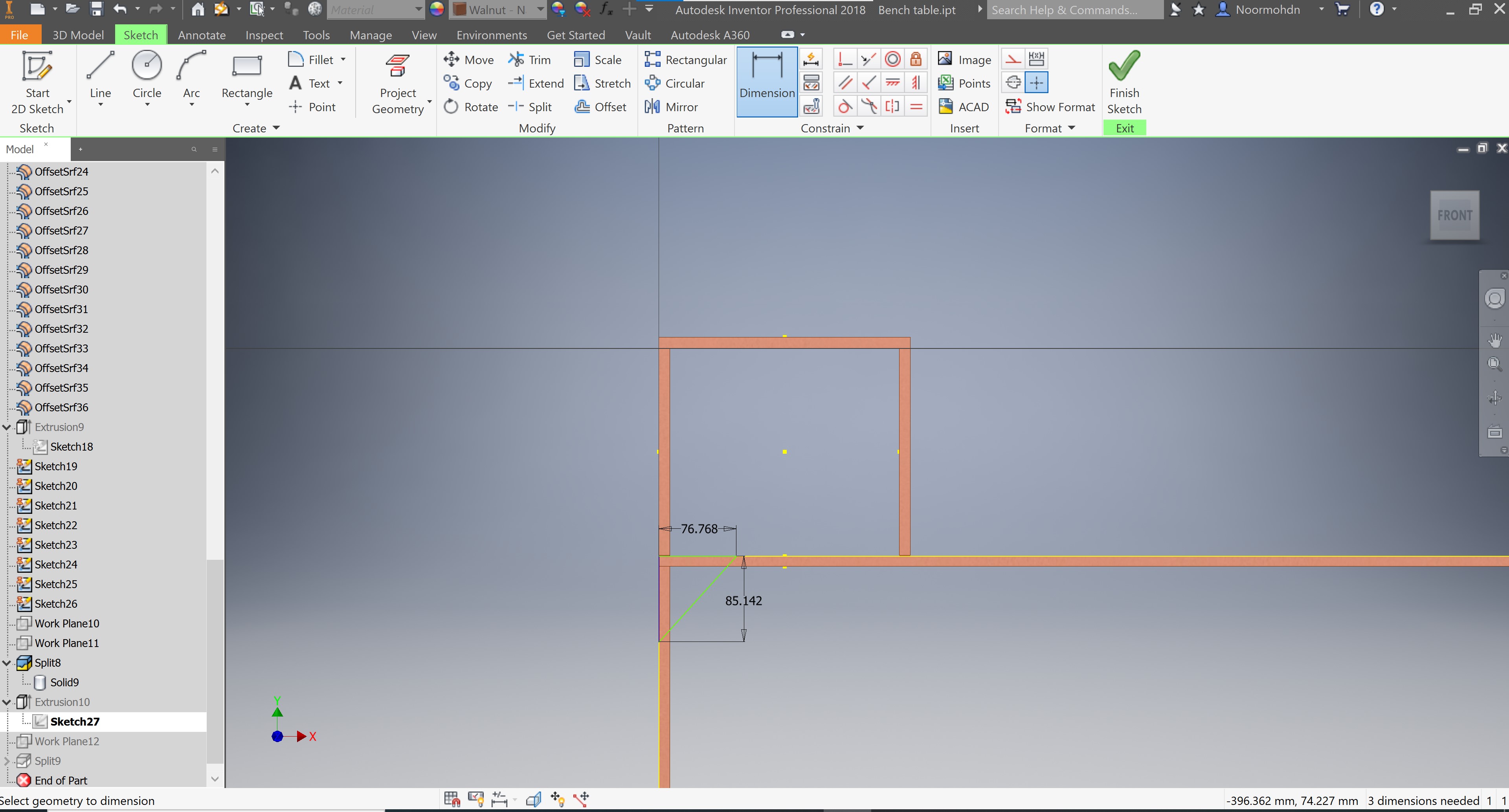
A sketch is made on the above surface to one of the box, to design the joint section I picked according to the use and the assembly part to the design. The dimensions was not specific so I have decided to do 2 in each side of the above slab.
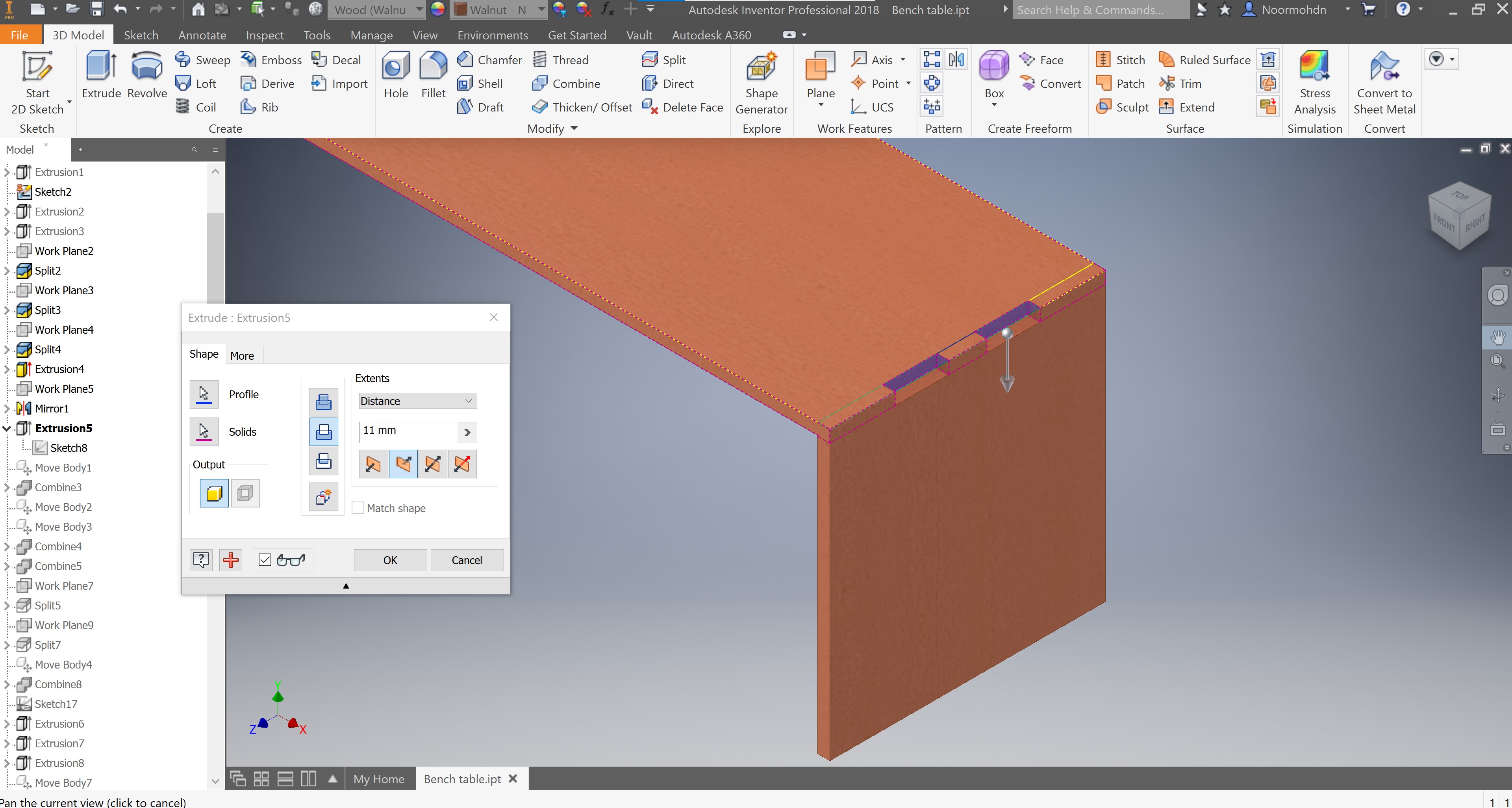
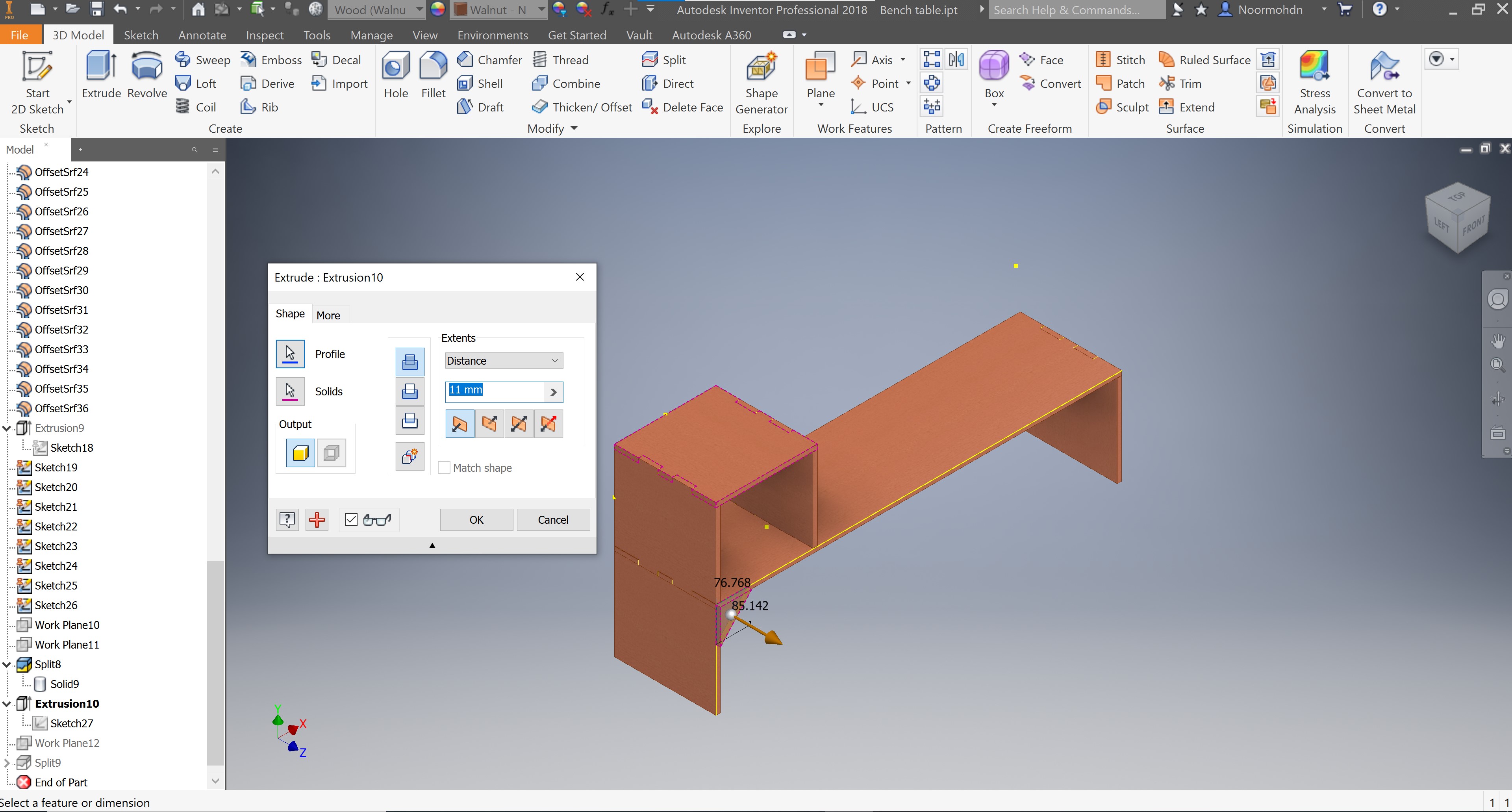
After drawing the joints sketch, I made an extrusion cut to the sketch to the extruded solids. The extrusion dimensions is stated on the following photo and pop up tab
A work-plane is made to do a mirror action to the drawing above with the joints to the joints linked to the ox and the bench table slab
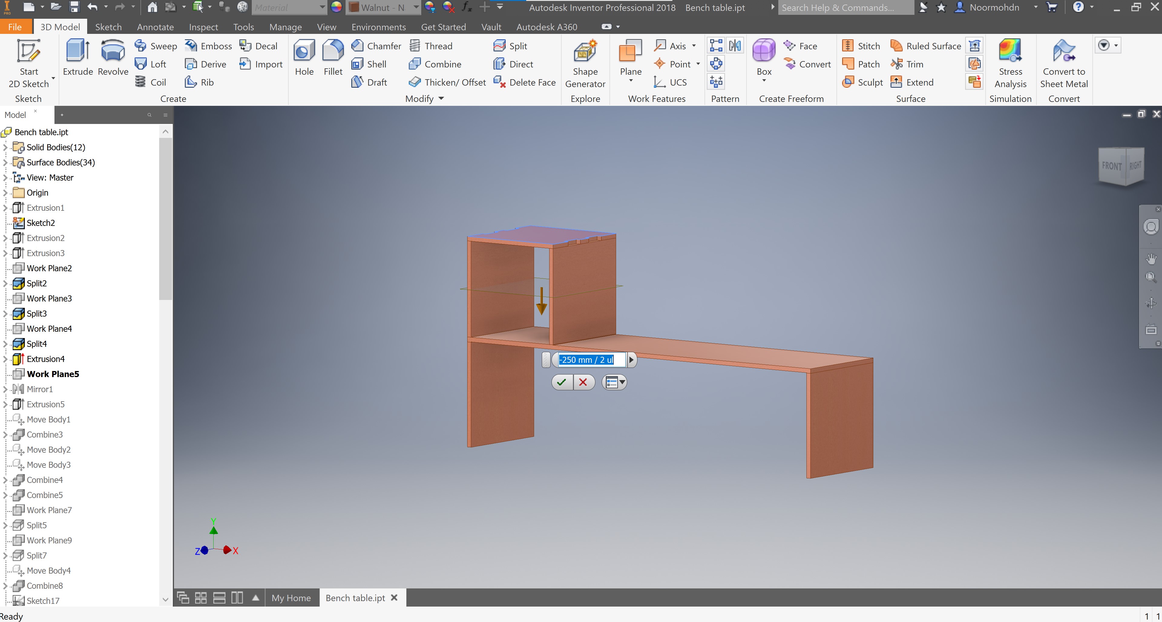
The mirror is made to the extrusion cut of the joints.
Then, another sketch is made to do the leg joint section of the bench table. The dimensions of the joints is similar o the one I made previously.
Then the extrusion cut is made as stated on the following photo.
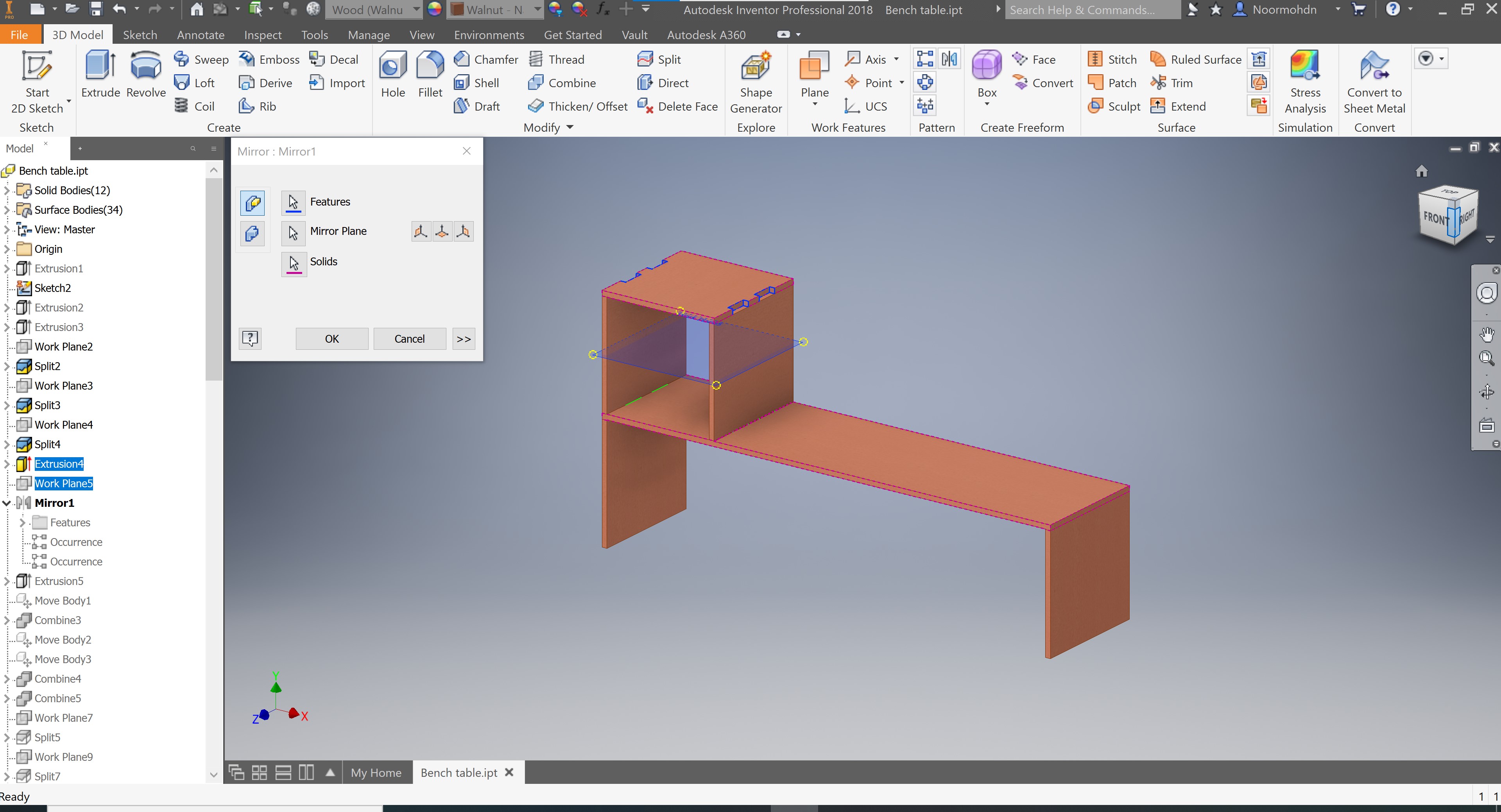
I moved the body to -11mm down in order so split them both. This step was another mistake.
I have combined the both body selected with the pink lining. As you can see in the following tab. This combine action will help me do the split action to have separated bodies.
Then I have done another move body operation in order to separate the parts, as you can see below.
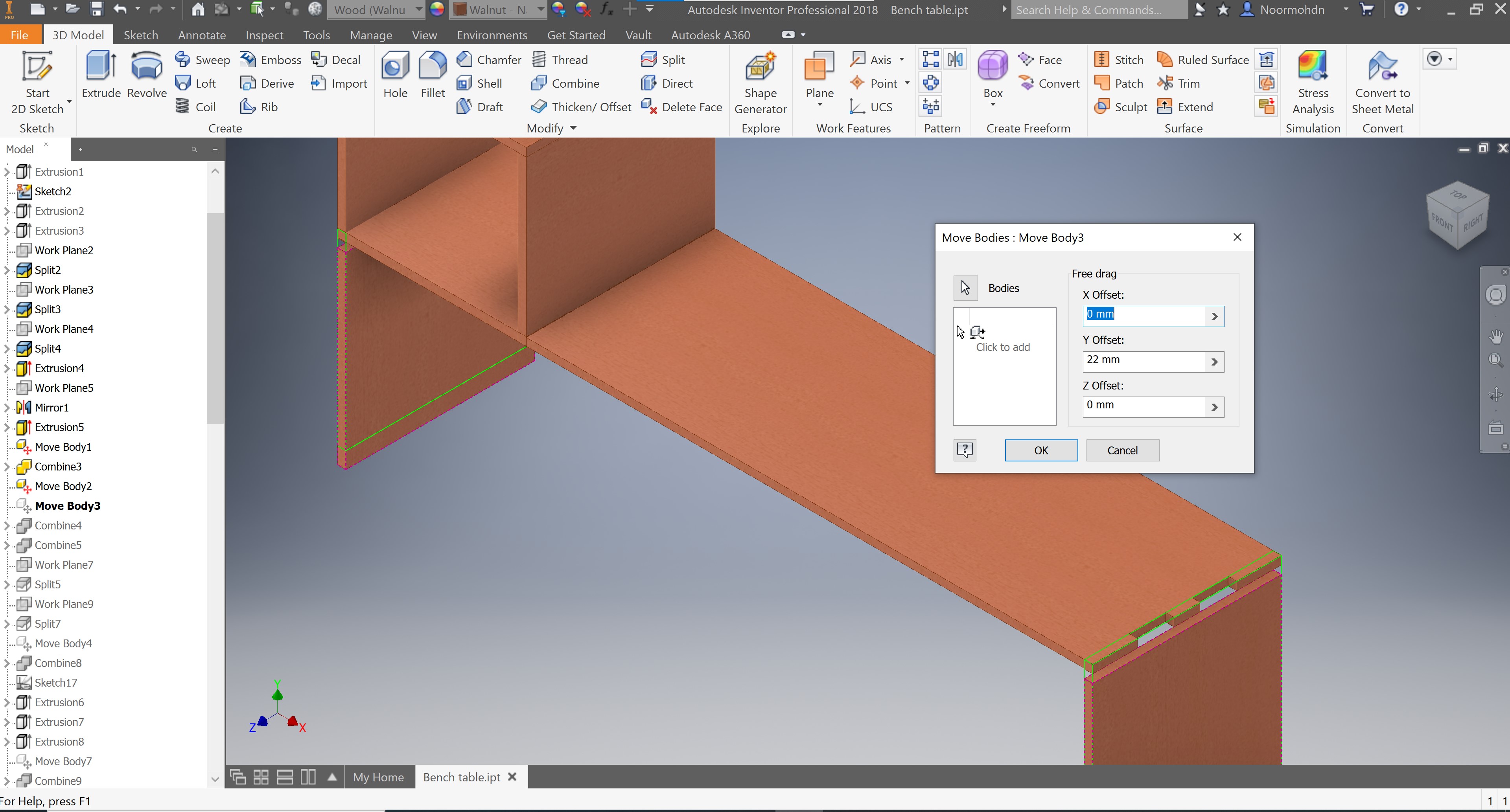
I moved the body to 22mm. This move body action should perform the joints I want to make. I did not have a strategy to do all the joints section on my design, that is why it was all over the place.
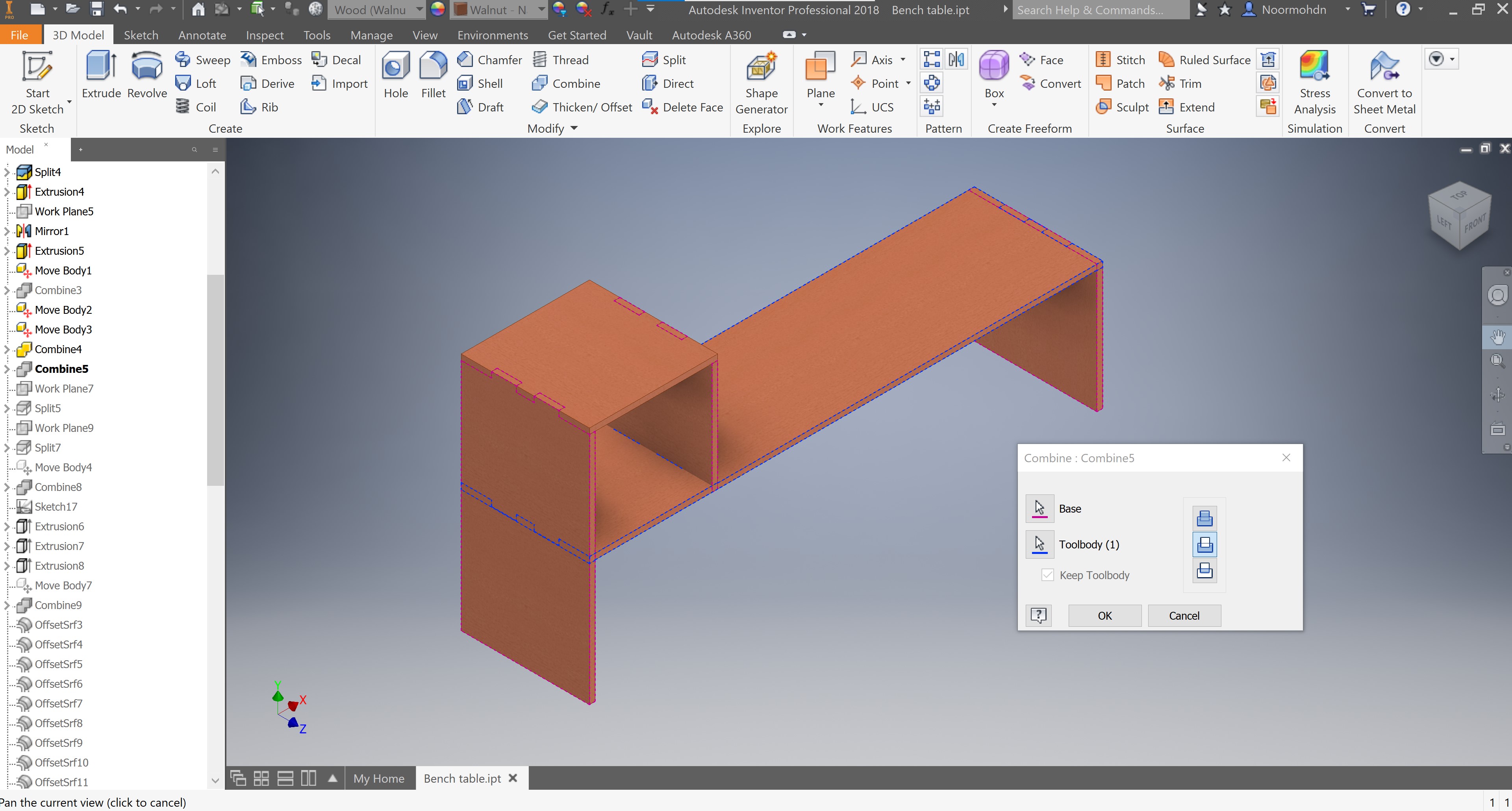
I have combined the bodies together again so I make the slab on the left of the box connected to the leg as one piece only and not separated pieces.
Then I did another combine to perform the action.
I did a mirror split in order to separate the both sides of the box because when I did the mirror of the joints both became as one solid which I do not want so another solid is made by this splitting action.
I did another work-plane to split the objects. Because the last action did not work. so I had to split twice.
On the following photo it shows that I have moved the body up in order to have a joint but it did not work after all either.
I have combined the bodies to perform the joints, as you can see in the screenshot below.
I had to draw another sketch to make extra extrusion because I had a mistake on the dimensions after moving the bodies.
After drawing the sketch I have extruded the part to adjust it.
Then I have done another extrusion to another part, which is not the same sketch to make it symmetrical.

Another extrusion to the other leg, as you can see the dimension of extrusion is stated on the pop up.
Then I have tried to move the body because it needed some adjustments.
After having the whole joints done, now from the fittings I have done I have to choose the offset dimension I am going to make in order to assemble the parts together after cutting them using the CNC machine. The offset amount I chose to perform is 0.13. This offset will be on each edge of the joints as you can see selected in light blue color on the following screenshot. As you can see in the “Model” tab in left where you can see the history of my design I have performed many offset iteration to each face of each joint in my design.

I have done another extrusion cut to adjust the design again and have the both legs aligned.
Then I have performed another split action because it turned up that the right slab of the box is somehow connected to the right leg of the bench table. And the splitting operation is shown below.
By this, we come to the end of the design of our bench table so I have put all these design into pdf file and uploaded to the CNC machine program.
Edit
After having the assembled part I saw that the design is weak and needed an external support so I have made some links supports shaped as triangle to each edge of the bench table. The following screenshot shows the drawing made in INVENTOR. And followed is the extrusion.
And then I have split the object to be only a separated solid. with drawing a plane behind the piece; which is the splitting tool.
Practical
In the practical section of our CNC cutting week, a background discussion have been explained by our tutor Abdulla. To highlight some of the important key words to discuss trough this section of our design which we will implement the design we have made previously and turning it into reality.
Safety First
Before running any machine the safety must be the first priority.
Your Fit
Wear your protection googles, to prevent any dust particles or hazardous parts to get in your eyes. And try to dress up with a suitable cloths and rolled up your sleeves if they are long. It is preferable to wear safety shoes, or if you do not have any wear a covered shoes where your feet is fully protected. 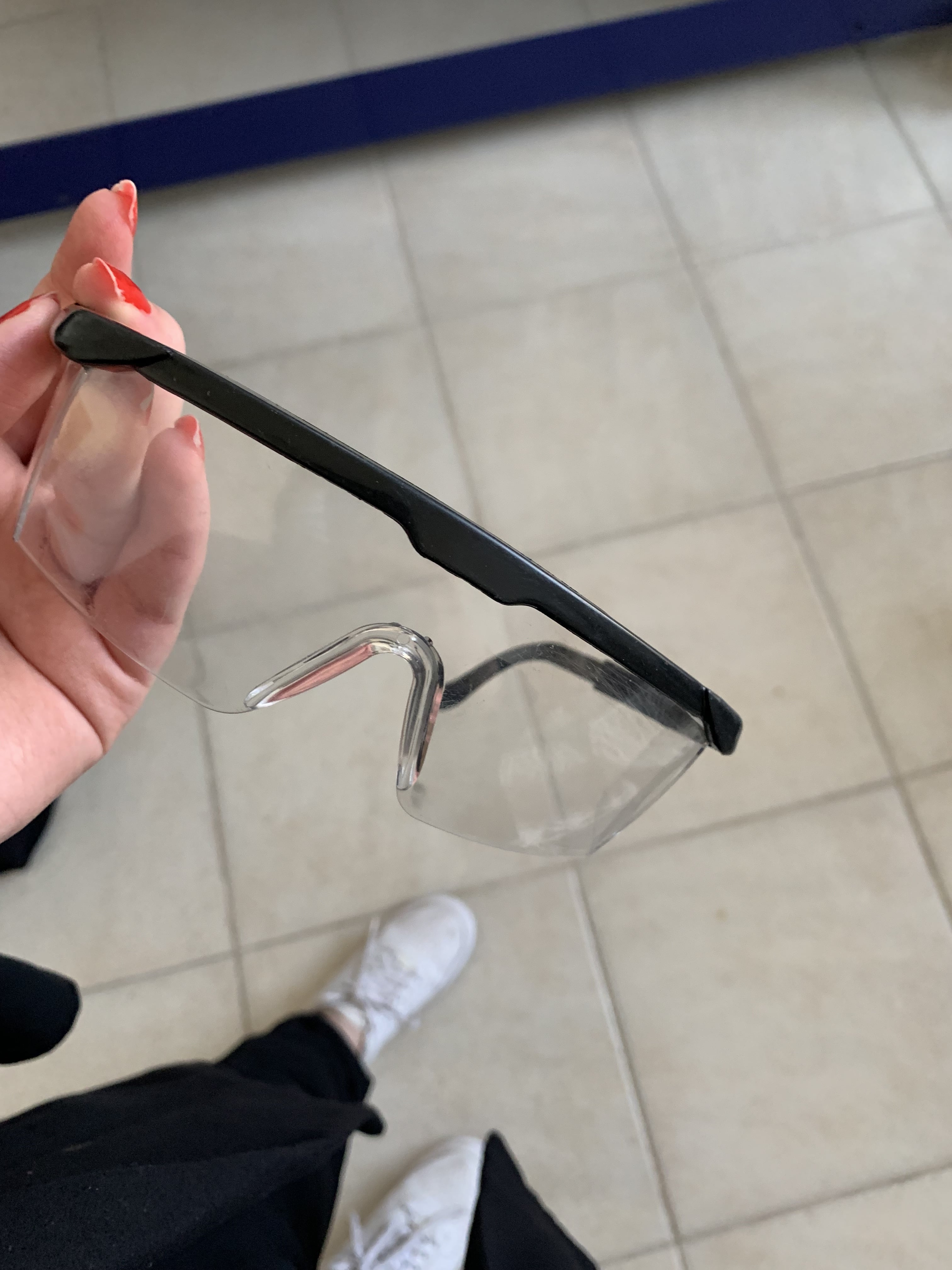
Machine Safety
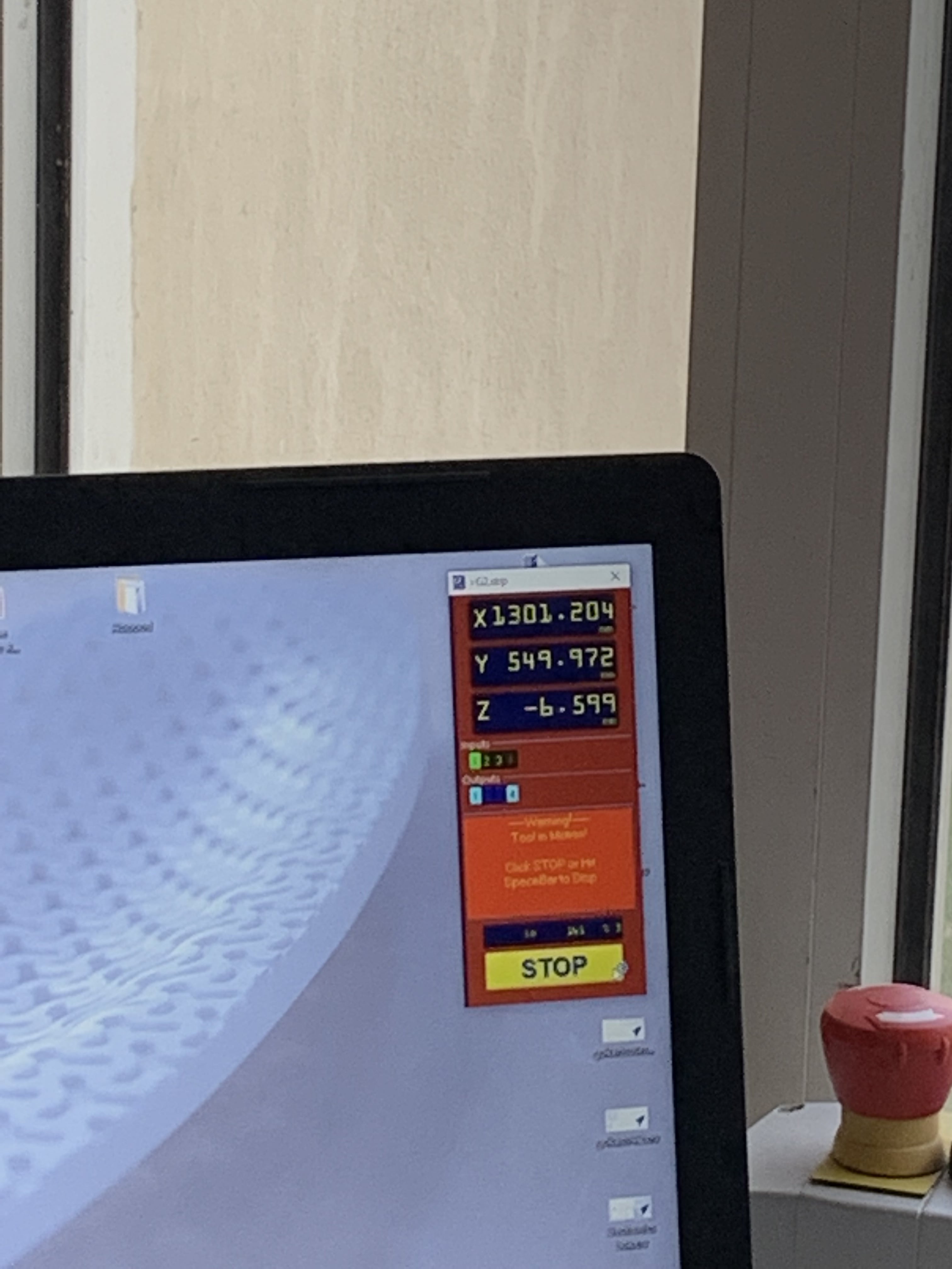
There are couple of ways’ to stop the machine in any of argent cases one of them is clicking on the following button which is connected directly with the software which is responsible to run the machine. Thus, you cannot use the laptop while the machine is operating.
 Further more buttons are placed on the actual machine to stop any argent cases occurred during the cutting process.
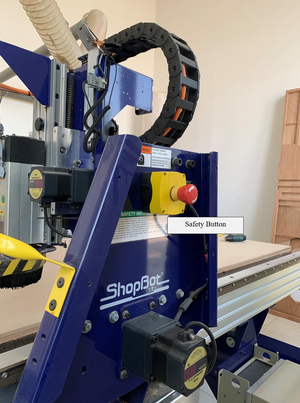 The following key and button is to turn on the actual machine, so make sure it is where you desire it to be.

Know the CNC Machine
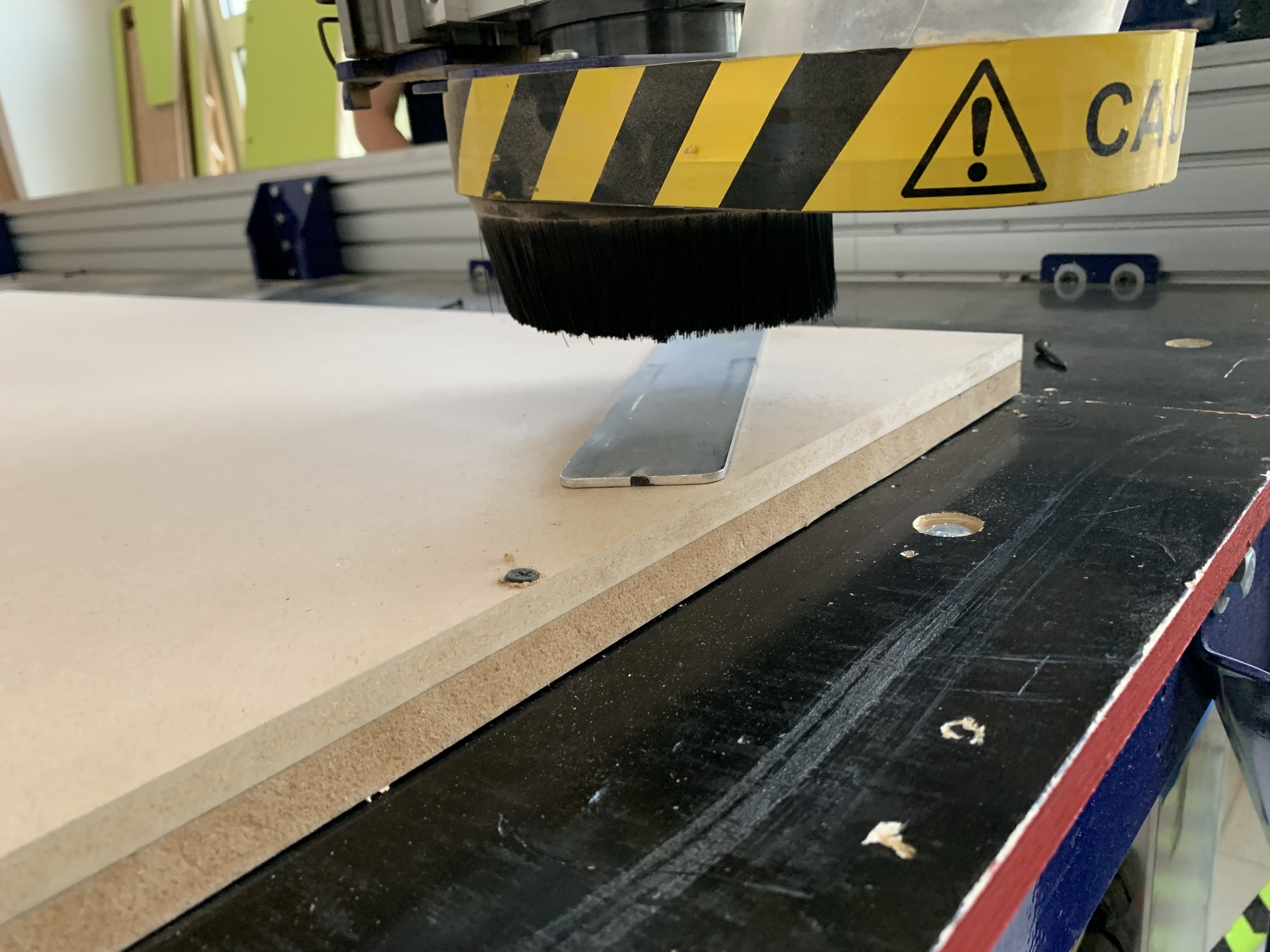
Tool calibration
To make sure that the drill is calibrated on the z axis of the machine we use kind of a tool that didact the z axis to it. It is a sensor tool that is connected to the power system which is connected to the software responsible to run the machine. Place the metal tool beneath the drill, then move the drill to touch the surface of the tool to detect the axis. The following photos shows the process, by first adding the metal piece, and the cord which is connected to the power supply.
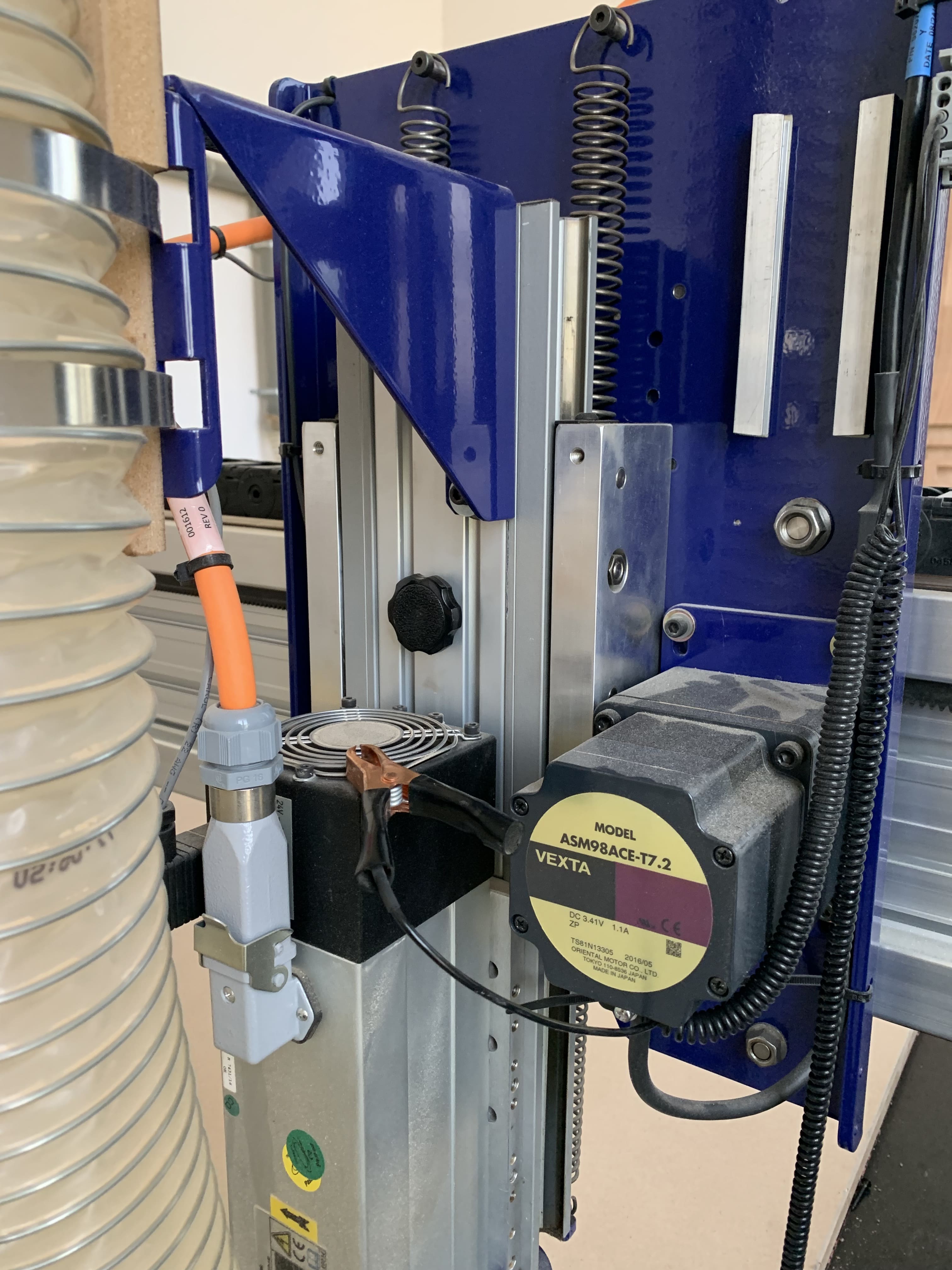
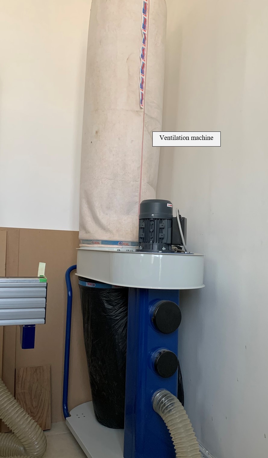
Ventilation
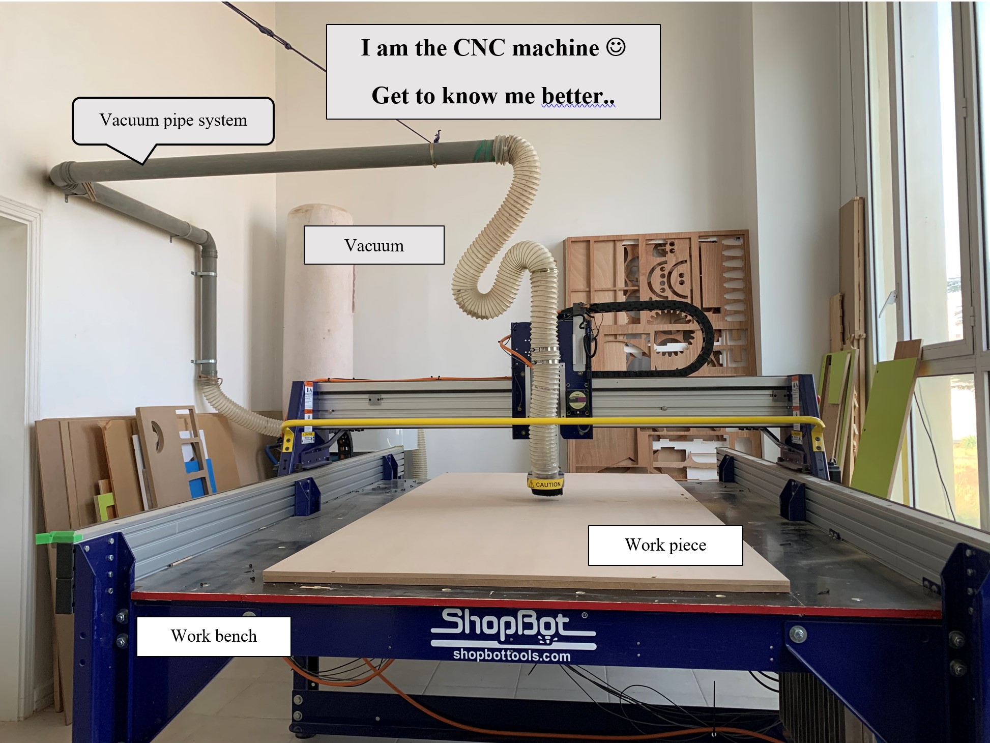
As you can see on the CNC photo above there is ventilation system which is a pipe system connected from the drill to the ventilation machine. the ventilation machine is shown in the following photo.
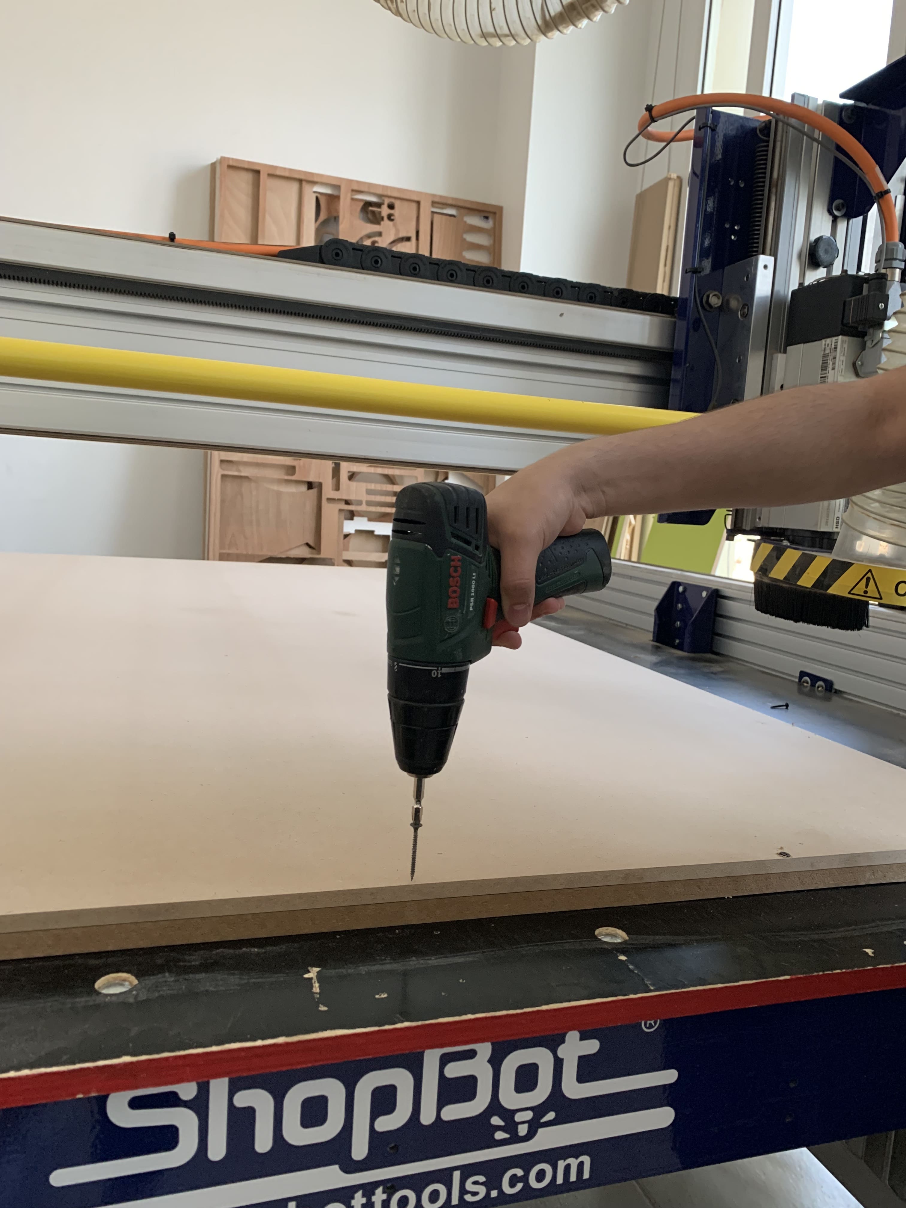
Work Piece
The work piece where we are working with is clipped into the station bench of the CNC machine. We used nails to fix the work piece into another sheet which is called the sacrifice sheet, this sacrifice sheet will prevent in design errors occurred on the work piece. The drill bit if it went to a deeper depth level it will goes into the sacrifice sheet. The following photo shows the action of fixing the work sheet. The material used to design my bench table is plywood; same material shown in the photo.
Work station
The work station will have couple of things such as your laptop and the button which is discussed before as you can see in the picture.
After running the cutting machine you can see through your monitor which is your laptop screen how the feed rate and the spindle speed is moving. Setting this parameters is discussed on the group assignment assigned for us.
CNC Program
Unfortunately, I do not have the screenshots of my design performed in the CNC program. And if you want more information about “VCarve Pro”, which is the program that we use for the CNC machine you can follow my friend Batool Website to know better about the steps. I was with her doing her table supervised by Abdulla Fadi.
Final
After completing the design and cutting all the part needed to assemble our design.
We remove each piece using a scraper tool or any useful tool. As you can see the following photo shows the operation. 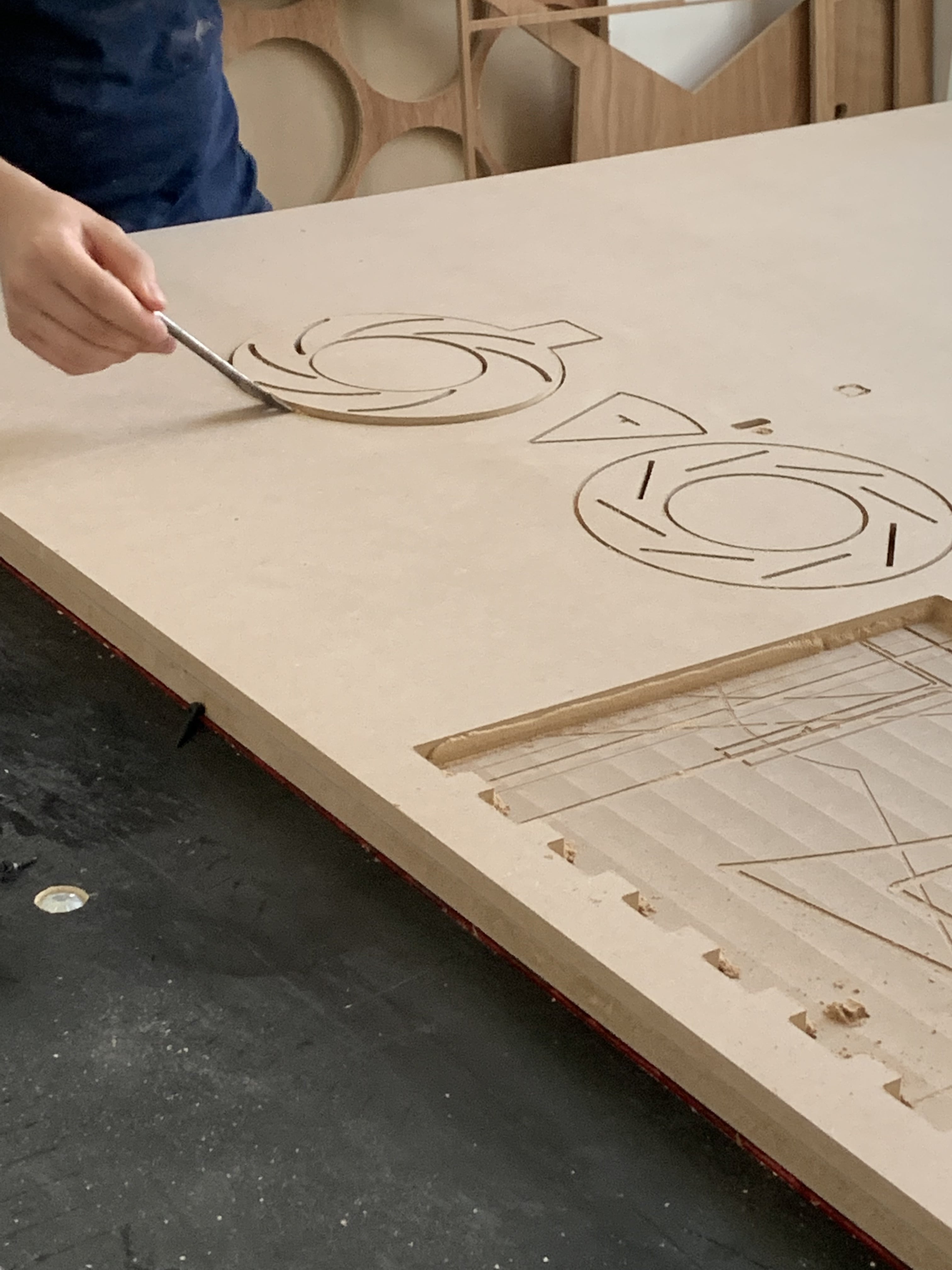 Thus, we file the surface of our pieces to have a better surface finish for our pieces.
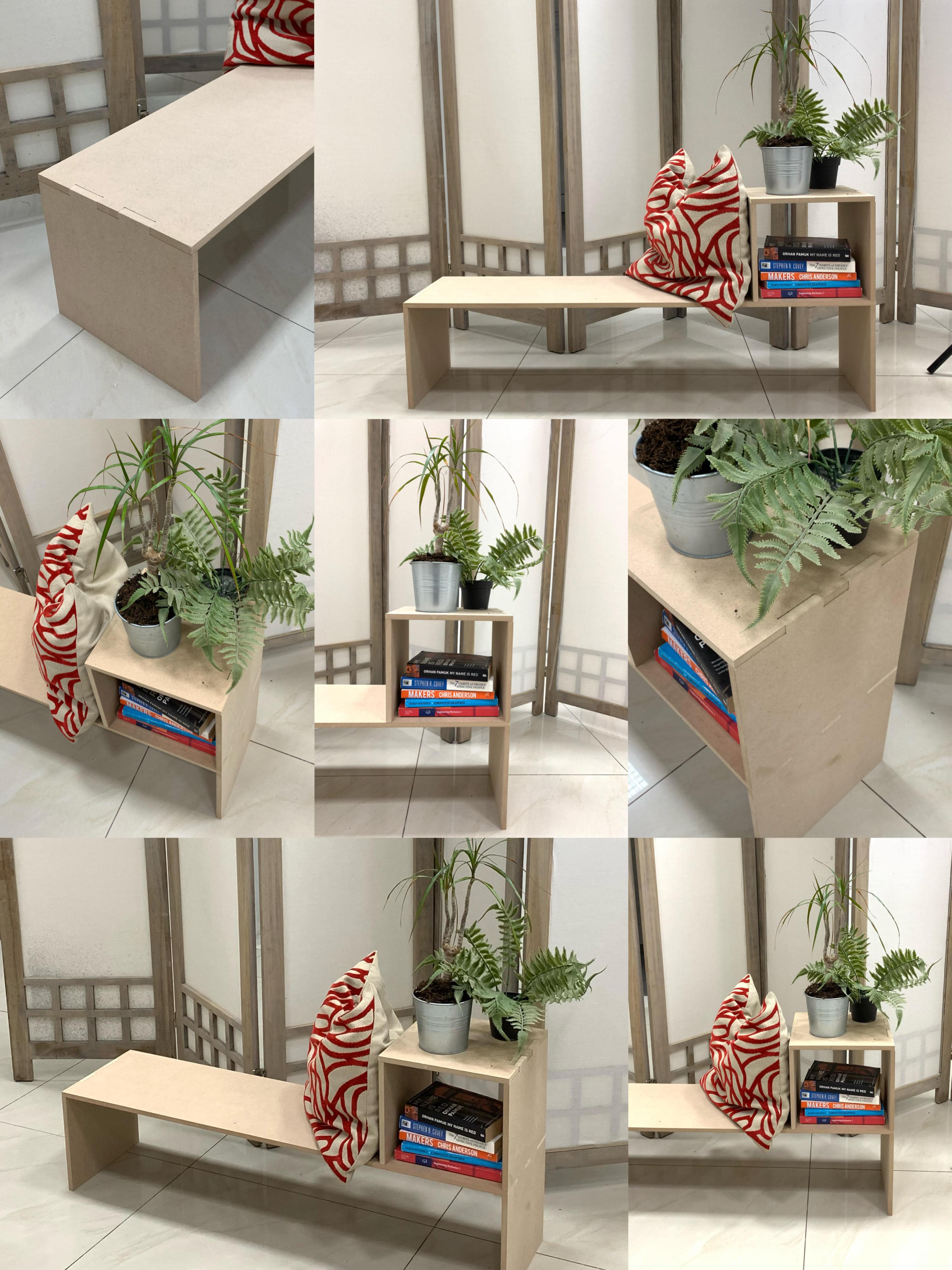
Finally completing the design to have the parts functioned to our desire. As you can see in the following grid the photos of my final project, my final project missing the support parts as they still not completed yet.
Thus, we file the surface of our pieces to have a better surface finish for our pieces.
Finally completing the design to have the parts functioned to our desire. As you can see in the following grid the photos of my final project, my final project missing the support parts as they still not completed yet.