4. Embedded programming
This week I learned what is arduino device and read its datasheet, program it using two different softwares.
Datasheet
I read the data sheet:
Sensors:
-9 axis IMU: measures board orientation or measure shocks, vibrations, acceleration and rotation speed.
-Barometer and Temperature Sensor: measures ambient pressure.
-Relative humidity sensor: measures ambient humidity.
-Digital proximity, Ambient light, RGB and Gesture sensor:
-Digital microphone
-Crypto chip
-MPM3610 DC-DC: it regulates input voltage. (maintains the voltage of a power source within acceptable limits)[1].
Pinouts:
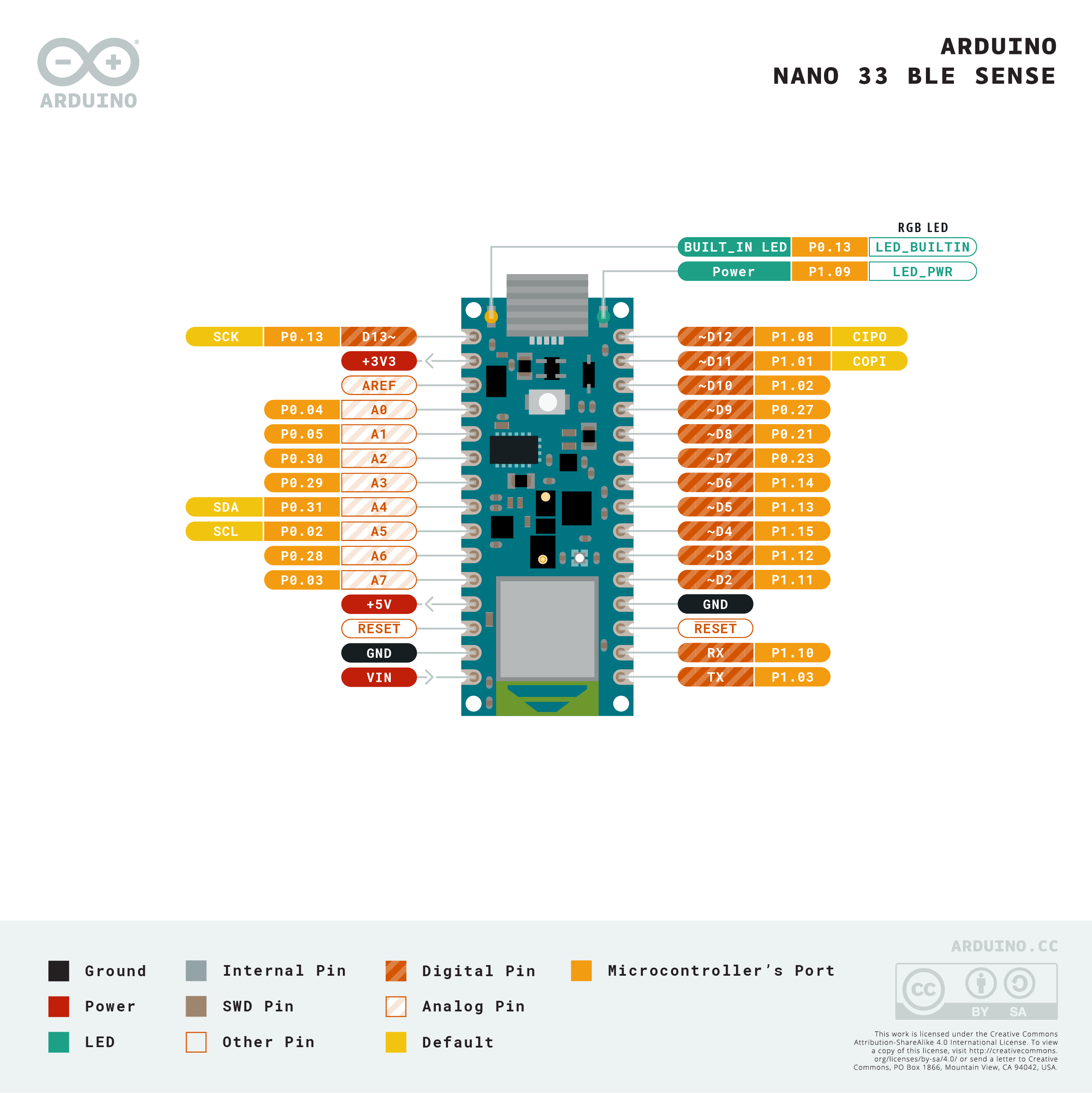
Digital and Analog:
There is two types of pinouts, analog and digital.
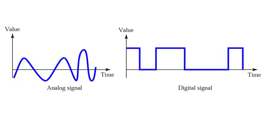
Digital(D2 to D12): It is used only for reading and writing high voltage (On) (3.3V) and low voltage (Off) (0V).
Some of the digital pins(D3,D5,D6,D9,D10) can be used as PWM, which is explained later in this documentation.
Analog(A0 to A7): It is used to read and write voltage variying between 0V to 3.3V.
A0 to A7 has ADC in, which is explained later in this documentation.
Some Abbreviated terms:
GND: Power ground.
GPIO: general-purpose input/output.
GPIO: are General Purpose Input Output and are pins on various processors that aren’t dedicated to anything. They’re designed for you to do input or output single bits.
-ADC in: Analog to Digital Converter.
-DAC: Digital to Analog Converter.
-PWM: Pulse Width Modulation.
Pulse Width Modulation(PWM): is a digital technology that uses the amount of power delivered to a device that can be changed. It generates analogue signals by using a digital source. A PWM signal is basically a square wave which is switched between on and off state. The duty cycle and frequency of a PWM signal determine its behaviour.[3]
An excellent video on youtube explaining PWM:
-SPI: Serial Peripheral Interface
n a computer, a serial peripheral interface (SPI) is an interface that enables the serial (one bit at a time) exchange of data between two devices, one called a master and the other called a slave . An SPI operates in full duplex mode. This means that data can be transferred in both directions at the same time.[4]
Programming
This Youtube tutorial helped me:
Arduino Workshop for Beginners
Arduino IDE
Download and Install
Follow the Tutorial about installing the device core
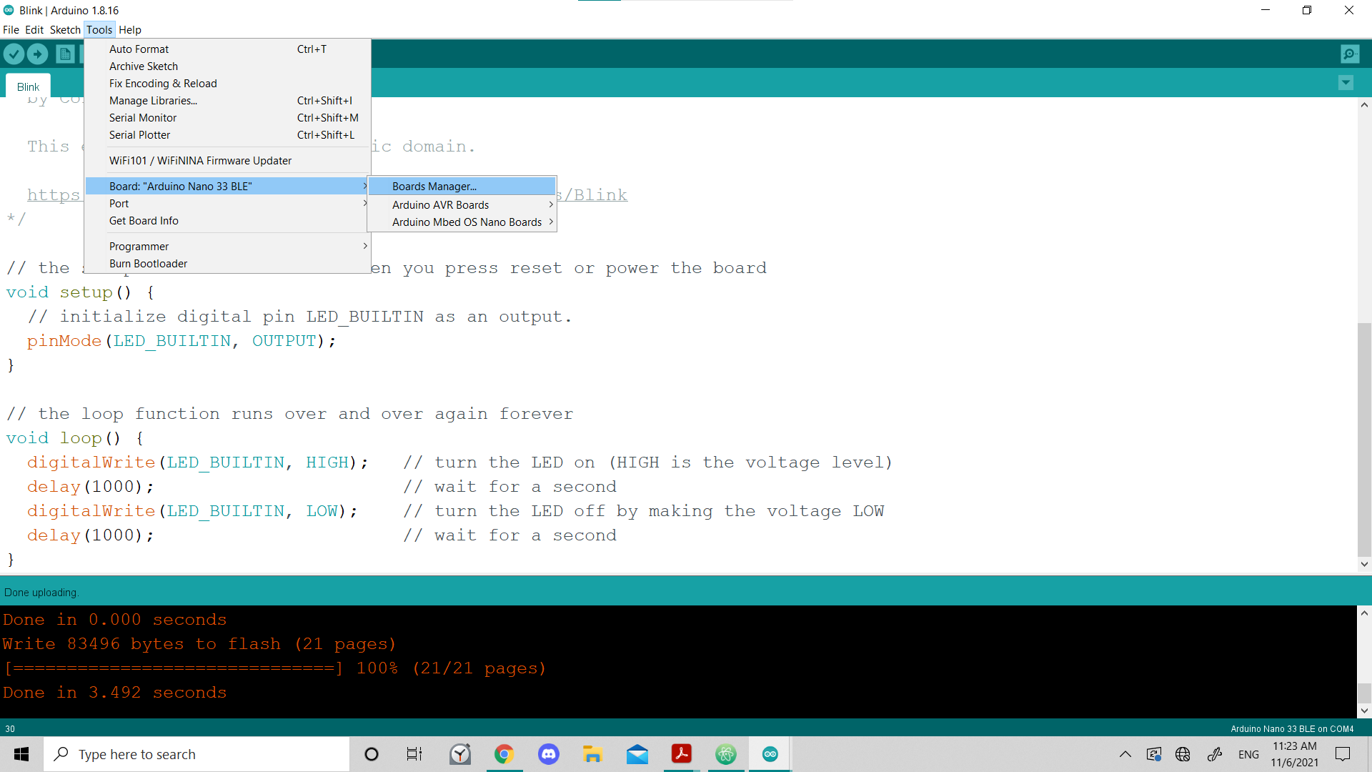
1- First, I choosed from tools bar, and then Board, Board manager:
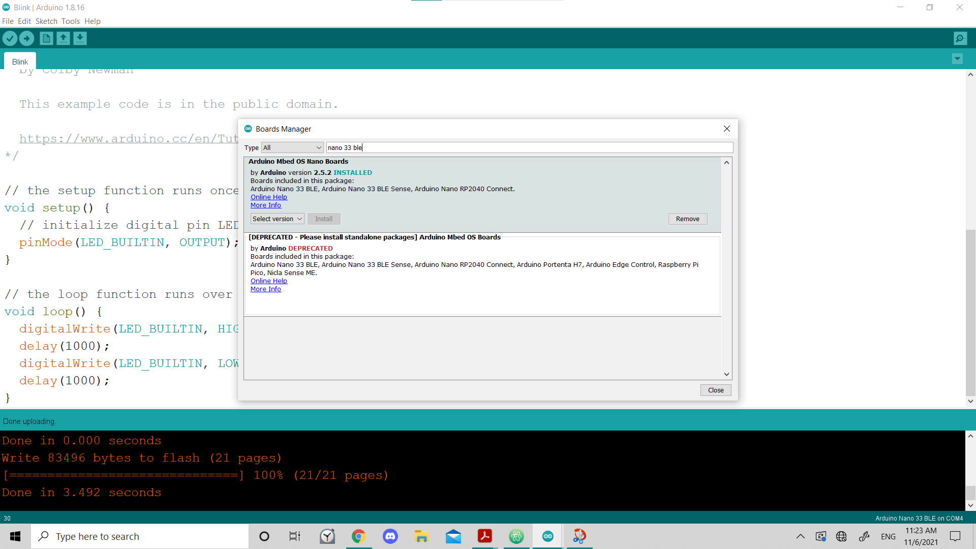
2- Searched for nano 33 ble, and insrtalled it:
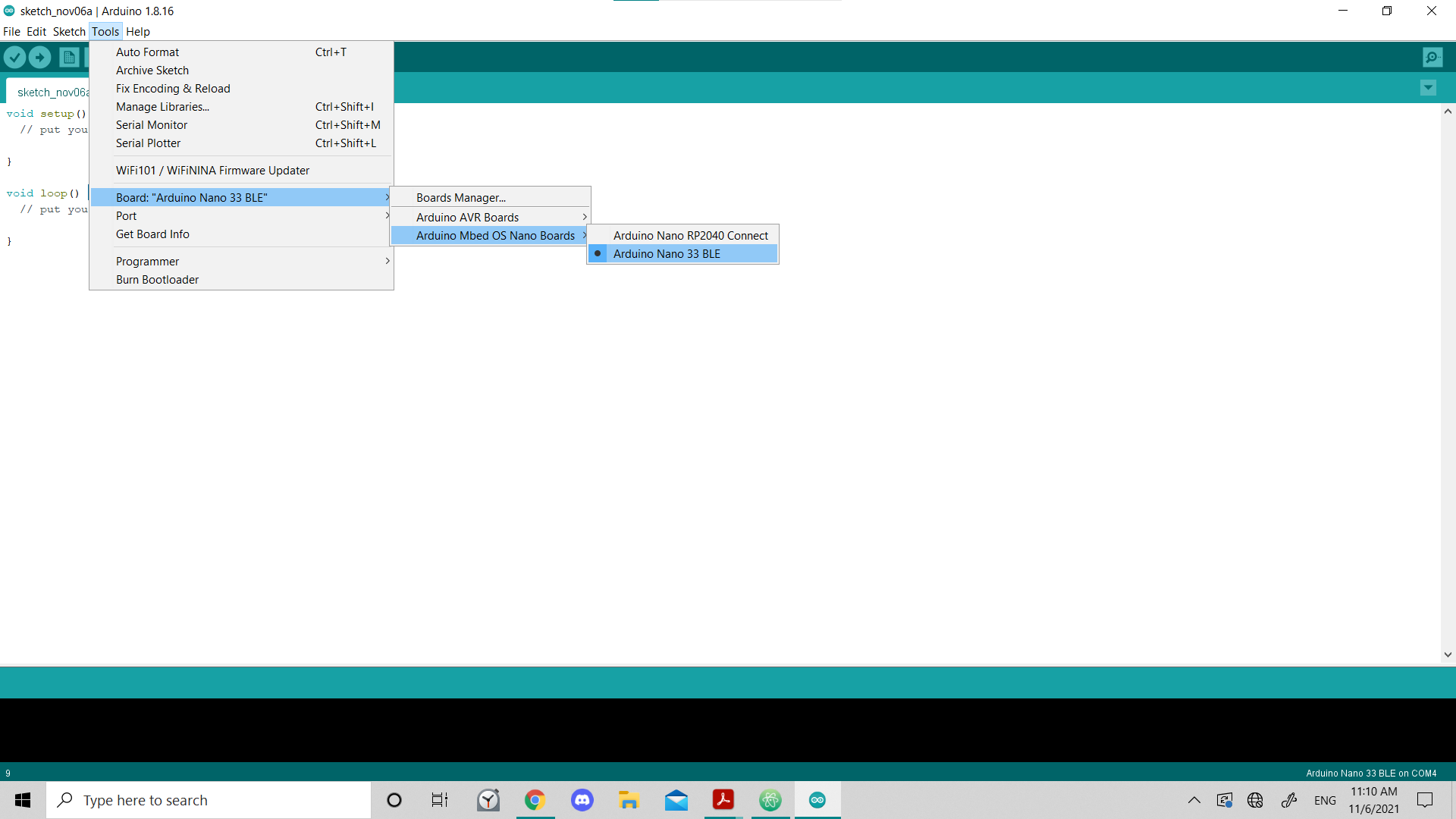
3- Then, I choosed from tools bar, and I choosed “Arduino Nano 33 BLE”:
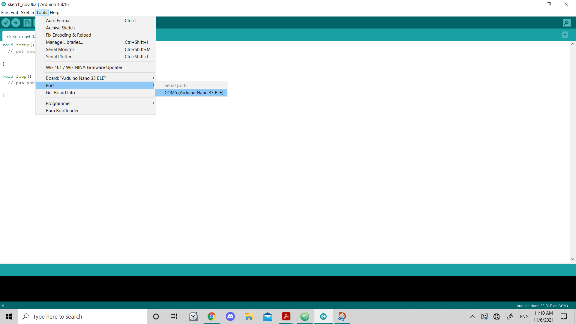
4- Last, I choosed Port, and then COM5 (Arduino Nano 33 BLE):
Trying Blink
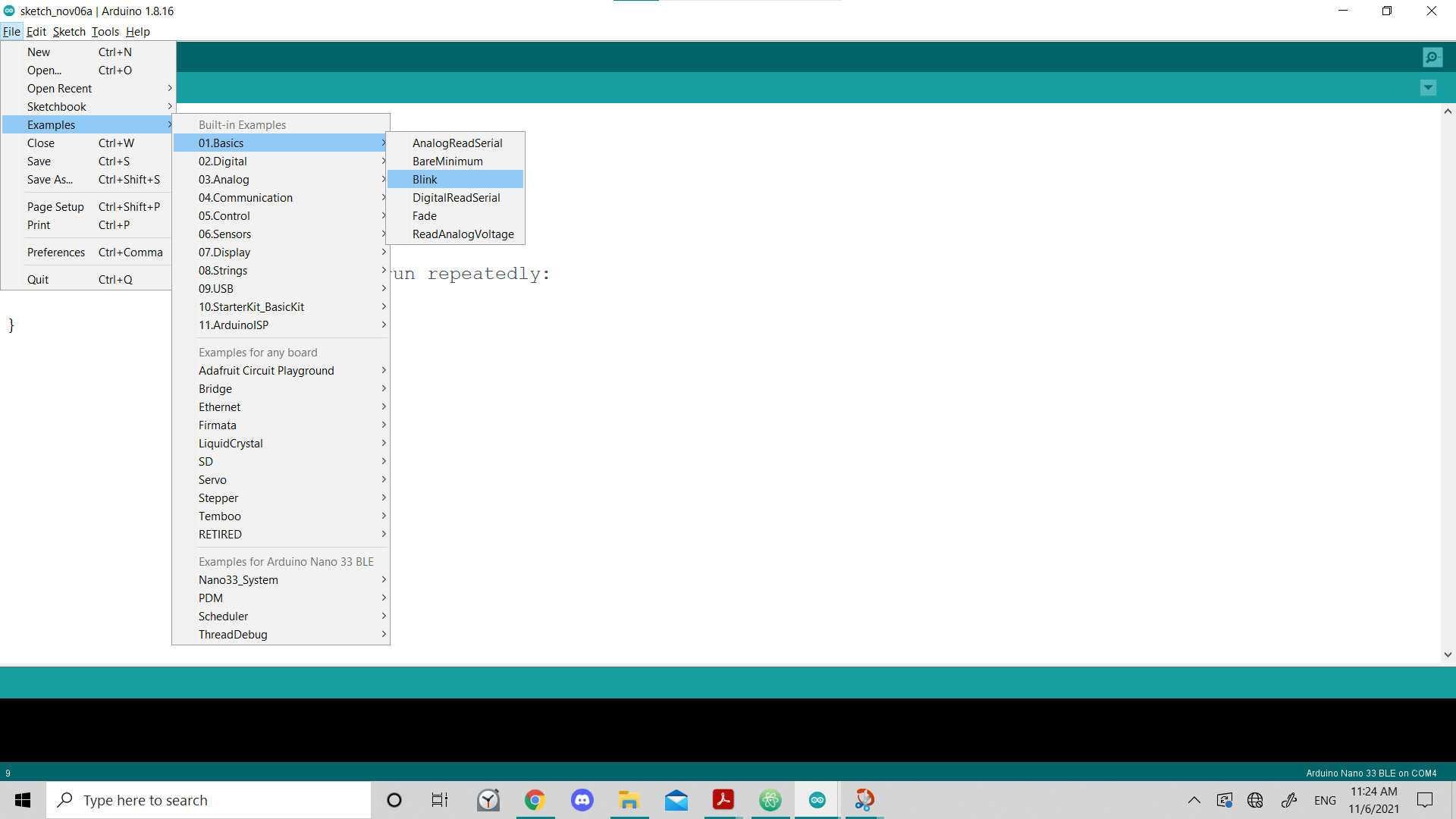
I tried using an example in the ide, which is “Blink”.
- I choosed Examples, from file bar, after that 01.Basics, and then Blink.
- I take a look at the code, and tried to understand it, and then clicked Upload, to run the code in the microcontroller:
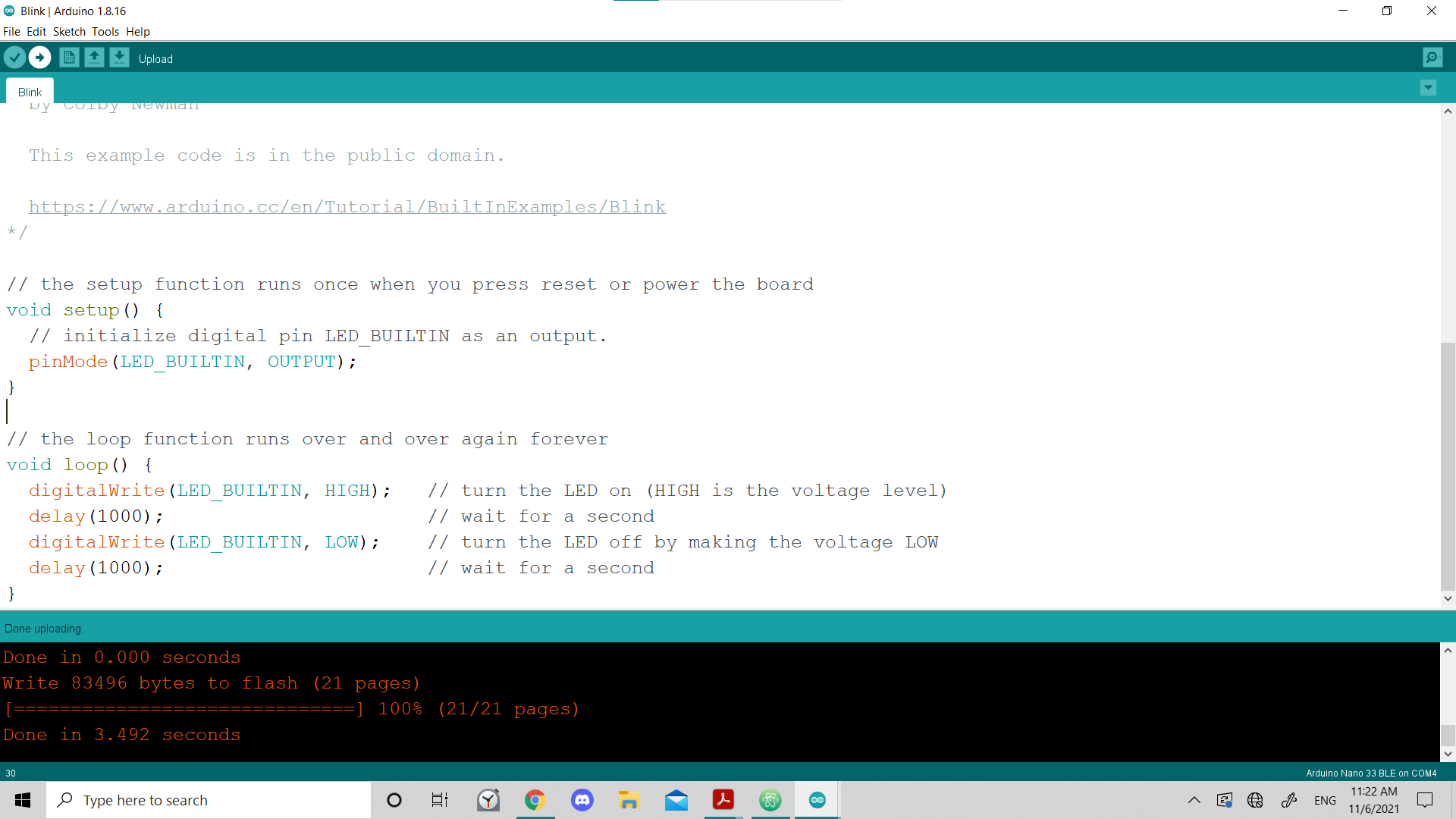
Then, the orange light in the microcontroller, was blinking as expected.
Challenges
Easy
Easy mode: Blink your led but have your blink delay periods be randomized values between 1 second and 5 seconds
Solution
- I used this website to get the syntax of generating a random number:
- The final code:
// the setup function runs once when you press reset or power the board
void setup() {
  // initialize digital pin LED_BUILTIN as an output.
  pinMode(LED_BUILTIN, OUTPUT);
}
//
// the loop function runs over and over again forever
void loop() {
  digitalWrite(LED_BUILTIN, HIGH);   // turn the LED on (HIGH is the voltage level)
  delay(1000 + (rand() % 4001));                       // wait for a second
  digitalWrite(LED_BUILTIN, LOW);    // turn the LED off by making the voltage LOW
  delay(1000 + (rand() % 4001));                       // wait for a second
}
Results:
| Lap | Time |
|---|---|
| 1 | 00:02.19 |
| 2 | 00:03.82 |
| 3 | 00:01.77 |
| 4 | 00:01.23 |
| 5 | 00:04.05 |
| 6 | 00:04.83 |
| 7 | 00:03.27 |
Medium
Medium mode: pre code your microcontroller to send a Morse code 1 word message and challenge a friend, family member, your colleagues or your instructor to figure it out. dot = 0.5 second light on. dash=1 second light on. gap between dots and dashes=0.5 second light off. gap between letters=2 second light off
Solution
// the setup function runs once when you press reset or power the board
void setup() {
  // initialize digital pin LED_BUILTIN as an output.
  pinMode(LED_BUILTIN, OUTPUT);
}

// the loop function runs over and over again forever
void loop() {
  //A
    //*
    digitalWrite(LED_BUILTIN, HIGH);   // turn the LED on (HIGH is the voltage level)
    delay(500);                       // wait for a second
    //gap
    digitalWrite(LED_BUILTIN, LOW);    // turn the LED off by making the voltage LOW
    delay(500);                       // wait for a second
    //-
    digitalWrite(LED_BUILTIN, HIGH);
    delay(1000);

  //gap btw letters
  digitalWrite(LED_BUILTIN, LOW);
  delay(2000);

  //L
    //*
    digitalWrite(LED_BUILTIN, HIGH);
    delay(500);
    //gap
    digitalWrite(LED_BUILTIN, LOW);
    delay(500);
    //-
    digitalWrite(LED_BUILTIN, HIGH);
    delay(1000);
    //gap
    digitalWrite(LED_BUILTIN, LOW);
    delay(500);
    //*
    digitalWrite(LED_BUILTIN, HIGH);
    delay(500);
    //gap
    digitalWrite(LED_BUILTIN, LOW);
    delay(500);
    //*
    digitalWrite(LED_BUILTIN, HIGH);
    delay(500);


  //gap btw letters
  digitalWrite(LED_BUILTIN, LOW);
  delay(2000);

  //I
    //*
    digitalWrite(LED_BUILTIN, HIGH);
    delay(500);
    //gap
    digitalWrite(LED_BUILTIN, LOW);
    delay(500);
    //*
    digitalWrite(LED_BUILTIN, HIGH);
    delay(500);

      //End gap
  digitalWrite(LED_BUILTIN, LOW);
  delay(5000);
}
Medium improved version
-
I used functions for dot, dash, gap and letter gap.
-
I got help for defining functions from: functions tutorial
// the setup function runs once when you press reset or power the board
void setup() {
  // initialize digital pin LED_BUILTIN as an output.
  pinMode(LED_BUILTIN, OUTPUT);
}

// the loop function runs over and over again forever
void loop() {
  //A
    dot(); gap(); dash(); letter_gap();
  //L
    dot(); gap(); dash(); gap(); dot(); gap(); dot(); letter_gap();
  //I
    dot(); gap(); dot();

  //End gap
    end_gap();
}

//Define functions:
void dash(){digitalWrite(LED_BUILTIN, HIGH);delay(1*1000);}

void dot(){digitalWrite(LED_BUILTIN, HIGH);delay(0.5*1000);}

void gap(){digitalWrite(LED_BUILTIN, LOW);delay(0.5*1000);}

void letter_gap(){digitalWrite(LED_BUILTIN, LOW);delay(2*1000);}

void end_gap(){digitalWrite(LED_BUILTIN, LOW);delay(5*1000);}
Ali Morse code video
Hard
Hard mode: you select the duration of the light being on and off while the program is running by entering it in the serial monitor. Write a code that takes the data from the serial monitor and delays by that amount of time.
I still didn’t try it.
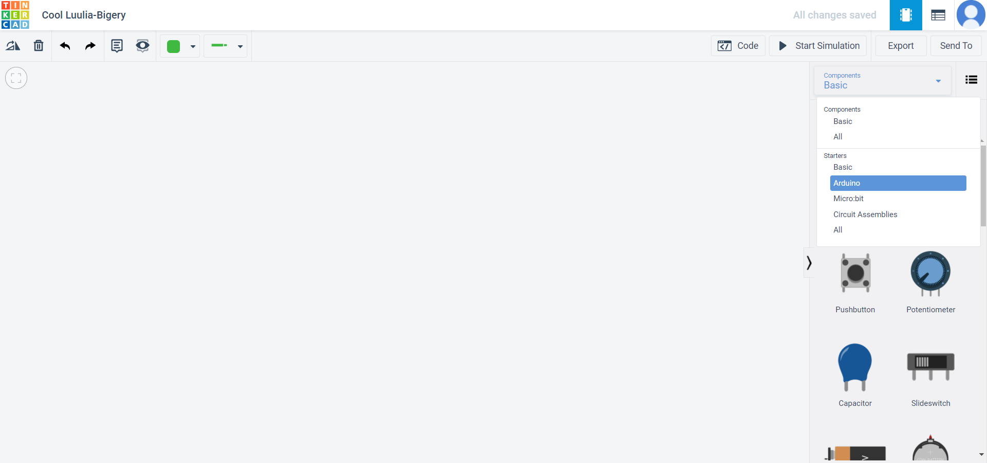
Tinkercad
Website: Tinkercad
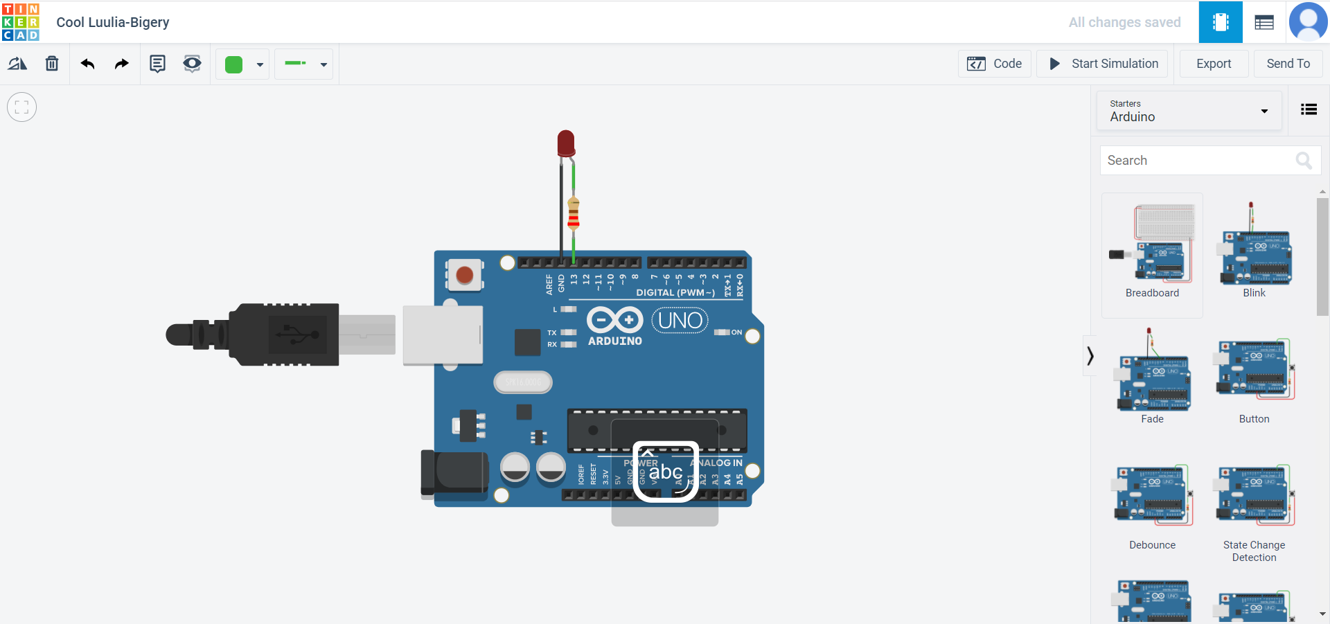
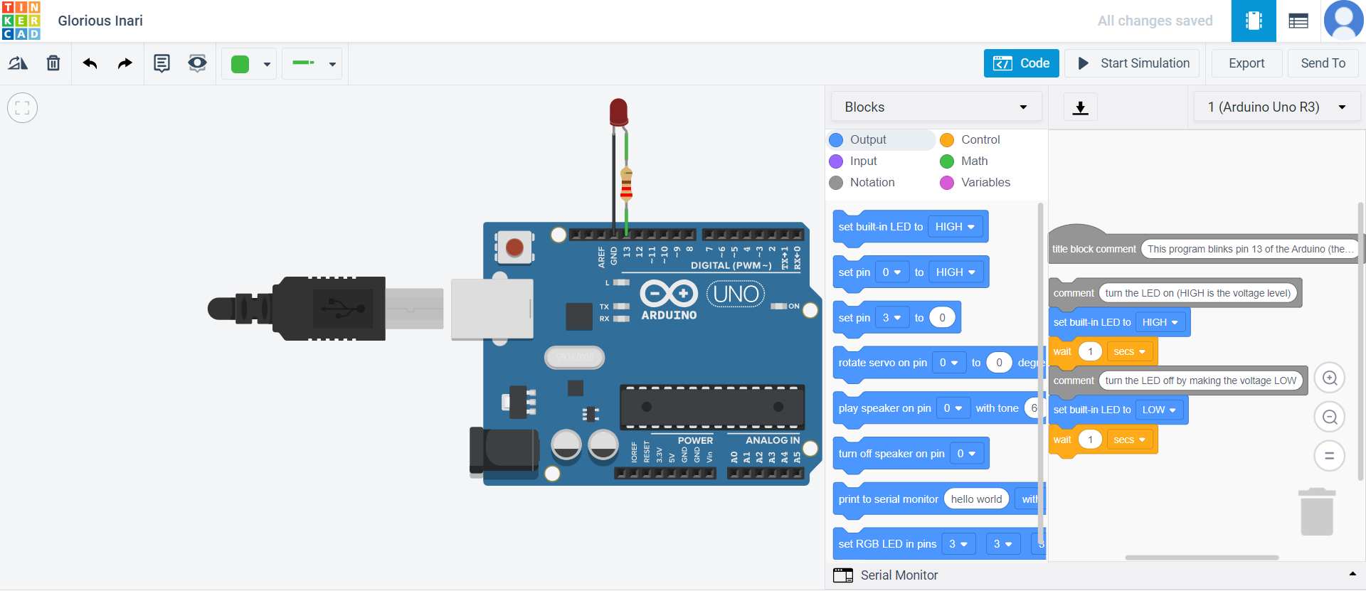
Trying built-in blink
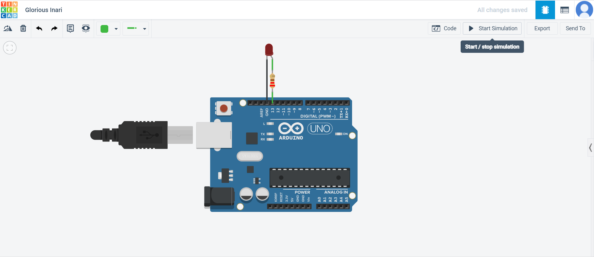
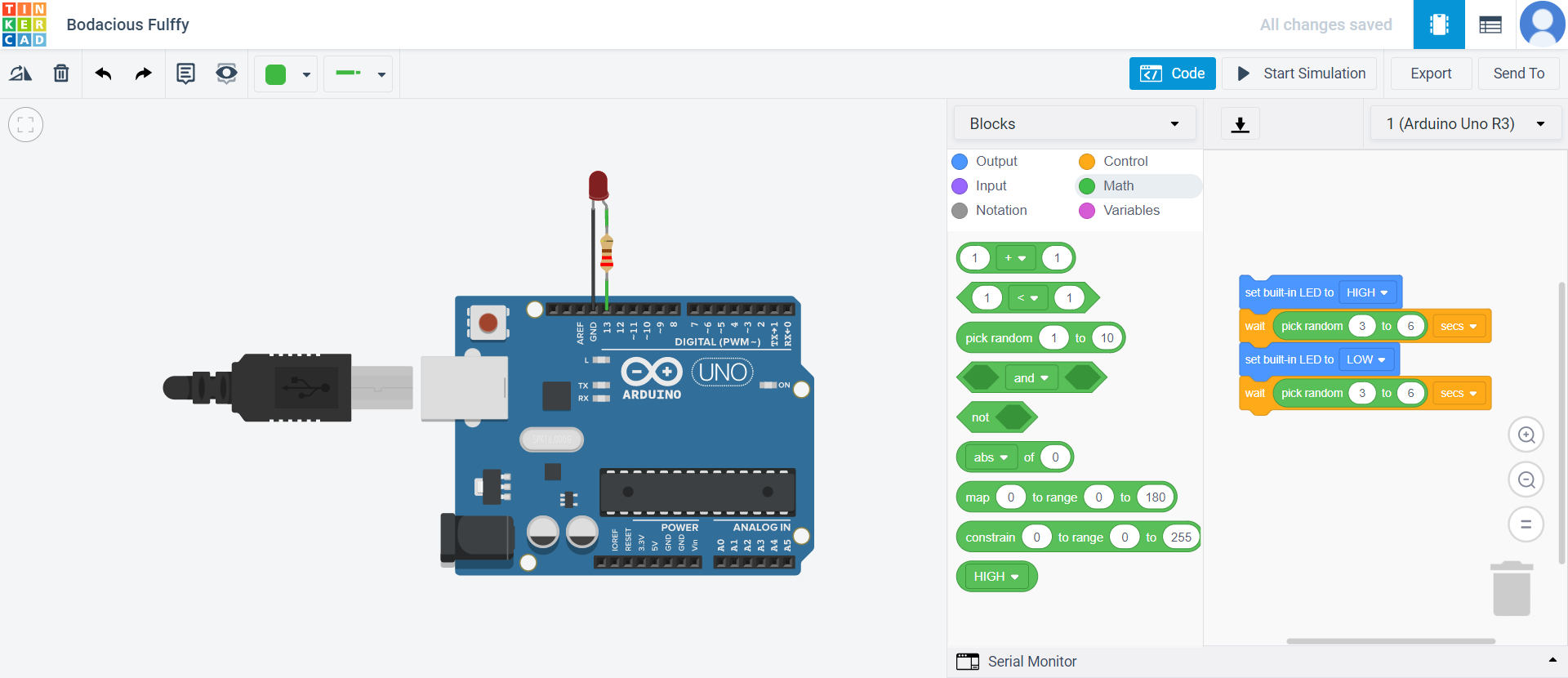
Trying random delays between light on and off
Results
| Lap | Time |
|---|---|
| 1 | 00:05.57 |
| 2 | 00:04.03 |
| 3 | 00:03.00 |
| 4 | 00:03.92 |
| 5 | 00:05.07 |
| 6 | 00:04.86 |
| 7 | 00:04.16 |
Useful links
Quotes and images from these websites:
Helpful website for Arduino IDE syntax: