Final Project: Maze Race
I worked with my colleague Kumail in this project, which is called Maze Race!
Out project is a physical maze, which is modifiable by changing the inner walls positions to make another puzzle! In addition, it is a Race, which means that you should finish the puzzle as soon as possible! This prototype can be played by moving the maze by hands, to move the ball into the final goal.
Design and digital fabrication
The details of this part is in My colleague Kumail’s page.
Programming, Input and Output devices
Part 1: Limit Switch and Button:
Limit Switch
I’ve gotten help from this website, in wiring and code: arduinogetstarted.com
I first tried to use the same program as the one in the website, and it worked well.
Linking it with the stopwatch
As for the stopwatch, I used the function “millis()”. This function calculates the time since the program started.
for the stopwatch to be in a pattern of a real stopwatch, where the mintutes, seconds and milliseconds are separated, I’ve gotten help from:
This portion of code, to print the time as a pattern of stopwatch:
if(Min < 10)
{
  lcd.print("0"); lcd.print(Min);
}
else lcd.print(Min);
lcd.print(":");
if(Sec < 10)
{
  lcd.print("0"); lcd.print(Sec);
}
else lcd.print(Sec);
lcd.print(".");
lcd.print(milliSec[0]); lcd.print(milliSec[1]);
Final code, for stop watch in serial monitor:
/*
 * Created by ArduinoGetStarted.com
 *
 * This example code is in the public domain
 *
 * Tutorial page: https://arduinogetstarted.com/tutorials/arduino-limit-switch
 */

#include <ezButton.h>

ezButton limitSwitch1(7);  // create ezButton object that attach to pin 7;
ezButton limitSwitch2(8);

unsigned long t1=0,t2,duration,Sec,Min;
String milliSec;

void setup() {
  Serial.begin(9600);
  limitSwitch1.setDebounceTime(50); // set debounce time to 50 milliseconds
  limitSwitch2.setDebounceTime(50); // set debounce time to 50 milliseconds
}

void loop() {
  limitSwitch1.loop(); // MUST call the loop() function first
  limitSwitch2.loop();

  if(limitSwitch1.isPressed())
  {
    Serial.println("Race started!");
    t1=millis();
  }

  milliSec = String((millis()-t1)%1000);
  Sec = ((millis()-t1)/1000)%60;
  Min = ((millis()-t1)/60000)%60;

  if(t1>0)
  {
    //Serial.println((millis()-t1)/1000);

        if(Min < 10)
    {
      Serial.print("0"); Serial.print(Min);
    }
    else Serial.print(Min);
    Serial.print(":");
    if(Sec < 10)
    {
      Serial.print("0"); Serial.print(Sec);
    }
    else Serial.print(Sec);
    Serial.print(".");
    Serial.print(milliSec[0]); Serial.println(milliSec[1]);
  }


  if(limitSwitch2.isPressed())
  {
    Serial.println("Race finished!");
    t2=millis();
    duration=t2-t1;
    Serial.println(duration/1000);
    t1=0;
    t2=0;
  }

}
Button
This portion of work is related to making a program, that make use of push button switch as a changing state tool, which will be used later to change from timer to stop watch and the way back.
I’ve gotten help from this website, in wiring and code: electroniclinic.com
The code in the end of this web page, which is titled as “Arduino Push Button Toggle Switch programming:”, is used for turning on and off an LED light, by just pressing the button. I’ve made a change in this code to work for the built in LED of the Arduino. this is the result I got:
Finally, I also made a change to let the button print a number 1 for state 1 and number 2 for state 2.
Final code for changing state:
int PUSH_BUTTON = 2;
int flag = 0;
int sflag = 0;
int state=1;
void setup()
{
  pinMode(LED_BUILTIN, OUTPUT);
  pinMode(PUSH_BUTTON, INPUT_PULLUP);
  digitalWrite(LED_BUILTIN, LOW);
  Serial.begin(9600);
}

void loop()
{

  if( (digitalRead(PUSH_BUTTON) == LOW) && (flag == 0) && (sflag == 0) )
  {
    flag = 1;
    state=2;
    sflag = 1;

  }

    if( (digitalRead(PUSH_BUTTON) == LOW) && (flag == 1) && (sflag == 0) )
  {
    flag = 0;
    state=1;
    sflag = 1;

  }
      if( (digitalRead(PUSH_BUTTON) == HIGH)) // if there is nothing in front of the sensor
  {

    sflag = 0;
    delay(100);

  }

  Serial.println(state);
}
Part 2: OLED Screen:
For this part, I used the code of the stopwatch part, but to print in the OLED screen instead of the serial monitor.
I got help from this video to Setup the screen, i.e., the wiring and trying an example.
First, I installed the libraries related to the OLDED Screen we are dealing with. Their names are:
Adafruit SSD1306
Adafruit GFX
Second, I tried the example included wiht the library from:
(File -> Examples -> Adafruit SSD1306 -> ssd1306_128*64_i2c)
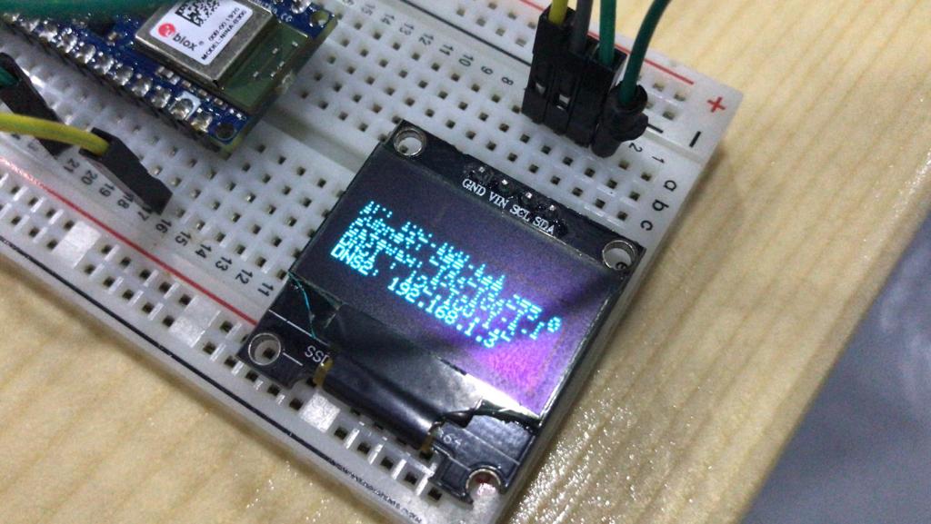
Result:
Then, I got help from this website in how to deal with the screen and how to print text:
Result, printing “hello world” and some text:
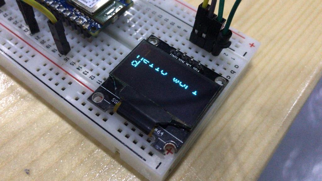
Comment:
As appears in the photos, there’s a part missing (cut) from the screen. I realized after finishing coding, that the screen has a problem, and tried another screen, and it worked well.
After that, I tried to use the stopwatch code, with changing printing from serial to the OLED display:
Preliminary Stopwatch:
Final code:
//
//
//
int PUSH_BUTTON = 2;
int flag = 0;
int sflag = 0;
int state=1;
//
//
//

//
//
//
boolean bol=true;
unsigned long t3,total=20000;
int j=-1;
//
//
//


//ol
//
//
#include <ezButton.h>

ezButton limitSwitch1(7);  // create ezButton object that attach to pin 7;
ezButton limitSwitch2(8);

unsigned long t1=0,t2,duration,Min,Sec;
String milliSec;
//
//
//


#include <SPI.h>
#include <Wire.h>
#include <Adafruit_GFX.h>
#include <Adafruit_SSD1306.h>
#include <Fonts/FreeMonoBoldOblique24pt7b.h>

#define SCREEN_WIDTH 128 // OLED display width, in pixels
#define SCREEN_HEIGHT 64 // OLED display height, in pixels

// Declaration for an SSD1306 display connected to I2C (SDA, SCL pins)
#define OLED_RESET     4 // Reset pin # (or -1 if sharing Arduino reset pin)
Adafruit_SSD1306 display(SCREEN_WIDTH, SCREEN_HEIGHT, &Wire, OLED_RESET);

void setup() {
  Serial.begin(9600);

  // SSD1306_SWITCHCAPVCC = generate display voltage from 3.3V internally
  if (!display.begin(SSD1306_SWITCHCAPVCC, 0x3C)) { // Address 0x3D for 128x64
    Serial.println(F("SSD1306 allocation failed"));
    for (;;); // Don't proceed, loop forever
  }


  limitSwitch1.setDebounceTime(10); // set debounce time to 50 milliseconds
  limitSwitch2.setDebounceTime(50); // set debounce time to 50 milliseconds


  pinMode(LED_BUILTIN, OUTPUT);
  pinMode(PUSH_BUTTON, INPUT_PULLUP);
  digitalWrite(LED_BUILTIN, LOW);
}

void loop() {
  change_state();
  if(state==1)
  {
    Serial.println("stopwatch");
    stopwatch();
  }
  else
  {
    Serial.println("timer");
    timer();
  }
}


void printText() {
  display.clearDisplay();
  display.setTextSize(2);
  display.setTextColor(WHITE);
  display.setCursor(5,30);
  display.print("Hello world");
  display.display();
}


void stopwatch() {
  display.clearDisplay();
  display.setTextSize(2);
  display.setTextColor(WHITE);
  display.setCursor(12,20);


  limitSwitch1.loop(); // MUST call the loop() function first
  limitSwitch2.loop();

  if(limitSwitch1.isPressed())
  {
    display.clearDisplay();
    display.setCursor(12,20);
    display.println(" Race");
    display.print("  started!");
    display.display();
    delay(2000);
    display.clearDisplay();
    t1=millis();

  }
  limitSwitch1.loop(); // MUST call the loop() function first


  display.setTextSize(2);
  display.setTextColor(WHITE);
  display.setCursor(12,30);

  milliSec = String((millis()-t1)%1000);
  Sec = ((millis()-t1)/1000)%60;
  Min = ((millis()-t1)/60000)%60;

  if(t1>200)
  {

            if(Min < 10)
    {
      display.print("0"); display.print(Min);
    }
    else display.print(Min);
    display.print(":");
    if(Sec < 10)
    {
      display.print("0"); display.print(Sec);
    }
    else display.print(Sec);
    display.print(".");
    display.print(milliSec[0]); display.print(milliSec[1]);
  }


  if(limitSwitch2.isPressed())
  {
    display.clearDisplay();
    display.setTextSize(2);
    display.setCursor(7,30);
    display.print("Race finished!");
    delay(2000);


    display.clearDisplay();
    display.setTextSize(2);
    display.setCursor(7,30);

    if(Min < 10)
    {
      display.print("0"); display.print(Min);
    }
    else display.print(Min);
    display.print(":");
    if(Sec < 10)
    {
      display.print("0"); display.print(Sec);
    }
    else display.print(Sec);
    display.print(".");
    display.print(milliSec[0]); display.print(milliSec[1]);


    t1=0;
    delay(3000);
  }

  display.display();
}


void timer() {
  display.clearDisplay();
  display.setTextSize(2);
  display.setTextColor(WHITE);
  display.setCursor(5,30);

  limitSwitch1.loop(); // MUST call the loop() function first
  limitSwitch2.loop();

  if(limitSwitch1.isPressed())
  {
    display.print("Race started!");
    t3=millis();
    bol=true;

    j=0;
  }

    if (j==0) {
       for (int i=0; i<=200 ; i++) {
     display.clearDisplay();
     display.setTextSize(1);
     display.setTextColor(WHITE);
     display.setCursor(12,30);

     display.print(total/1000);
     total=total-10;
     delay(10);

   }
  }

    if(total==0 && bol==true)
  {
    display.print("time over");
    total=20000;
    bol=false;
    t3=0;
  }

  display.display();

}


void change_state()
{

  if( (digitalRead(PUSH_BUTTON) == LOW) && (flag == 0) && (sflag == 0) )
  {
    flag = 1;
    state=2;
    total=20000;
    t3=0;
    sflag = 1;

  }

    if( (digitalRead(PUSH_BUTTON) == LOW) && (flag == 1) && (sflag == 0) )
  {
    flag = 0;
    state=1;
    t1=0;
    t2=0;
    sflag = 1;

  }
      if( (digitalRead(PUSH_BUTTON) == HIGH)) // if there is nothing in front of the sensor
  {

    sflag = 0;
    delay(100);

  }

  Serial.println(state);
}


}
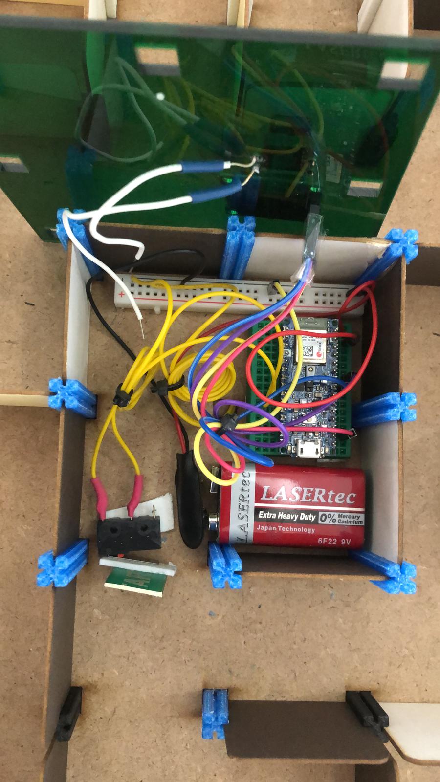
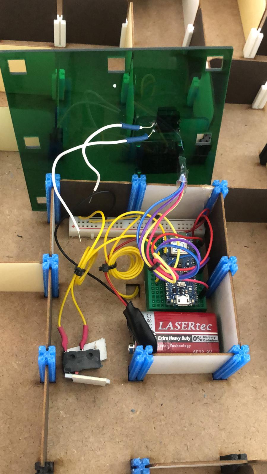
Part 3: Power and arranging wires:
For power, I connected a 9V Battery to the arduino.
I soldered wires to the two limit switches, and the button. I used heat shrink to Isolate the soldered portion. I used zip ties to bundle wires together.
I used a small bread board for the ardunio and the ground that is connected to all parts.
I stick the bread board and the battery with the maze by a two sided tape.
Assembling
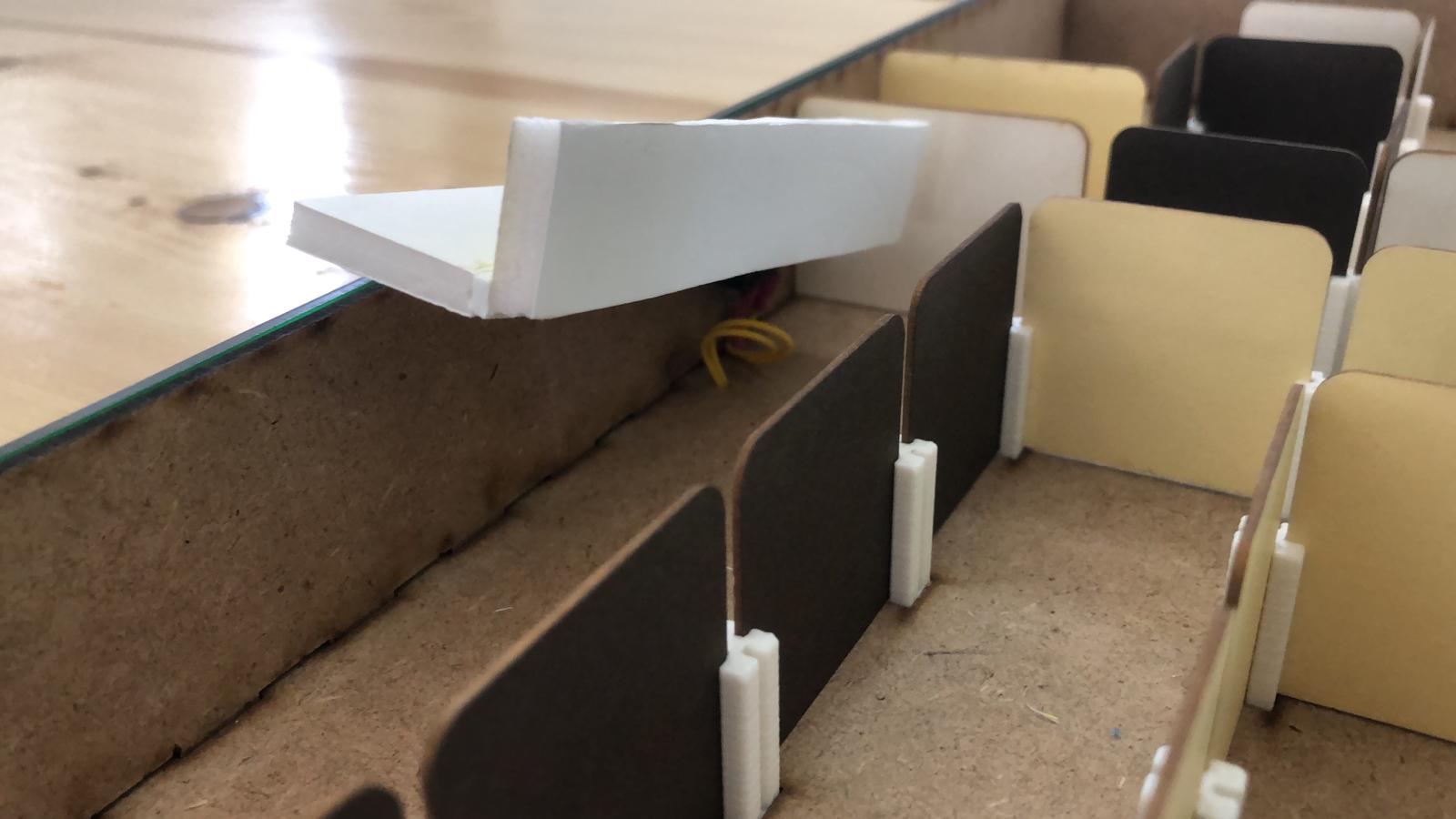
Maze
We put the two sheets in top of each other, and tried to assemble the outer wooden walls. we faced some difficulty in this becuase the outter walls don’t fit exactly with the maze, especially when we try to assemble the last two sides wall. we had to force the walls to be in its place by using the rubber hammer.
We then put the axles in their places, which was an enjoyable part. and then we put the inner walls according to the maze design (in Kumail’s page).
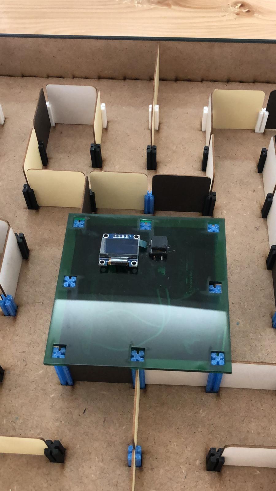
Electronics
We put electronics in the middle of the maze. by creating a roof (in Kumail’s page), that can be fixed in top of 8 axles, and the electronics are under this roof. Also, this region is surrounded by inner walls, so the wires and electronics are hidden.
To connect the wires to the start of the maze, we first tried to used guiding wire (as we had already assmbled the maze), and succeed. But we noticed that the maze is untied due to using the guiding wire. so we just needed to open the two platform sheets and connect the wire to the starting point of the maze, and then assemble the two sheets again.
Start limiting switch
Electronics inside
Final look
Further work
There is some ideas for future work:
1- Adding some nice sound effects as well as background music.
2- Adding record for top score.
3- Puttting sort of obstacles that appear and hide, alternatively. And also putting some holes for if the ball fall on them, the player faild the game!
4- Better triggers (limit switches) that allow for smooth clicking by the ball.
5- Putting some lights related to winning and losing the game.
Design files
Acknowledgement
I would like to thank instructors of Fab Academy 2021 program, Ms. Duaa Alaali, Mr. Abdul-Gafor, Mr. Abdullah Fadi and Dr. Salman Al-Oraibi, for thier great support for us. It is an honor to be a participant in this program.