2. Computer Aided design
This week we introduced to the CAD apps and how we can use them to create useful shapes.
This week I used Cuttle and gimps to create 2D designs also Fusion 360 and openSCAD to created 3D designs.
For 2D design:
Cuttle
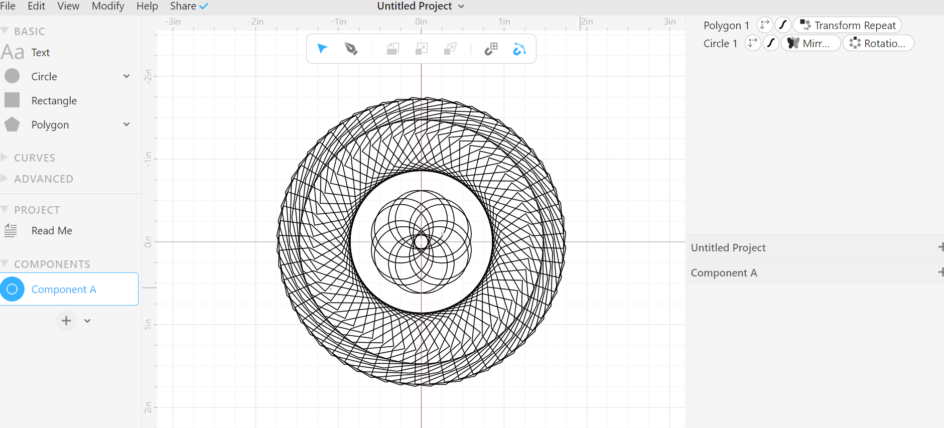
Cuttle is a useful program that helps to created 2D shapes that can be executed later by laser cutting.
I tried to do some sort of design.
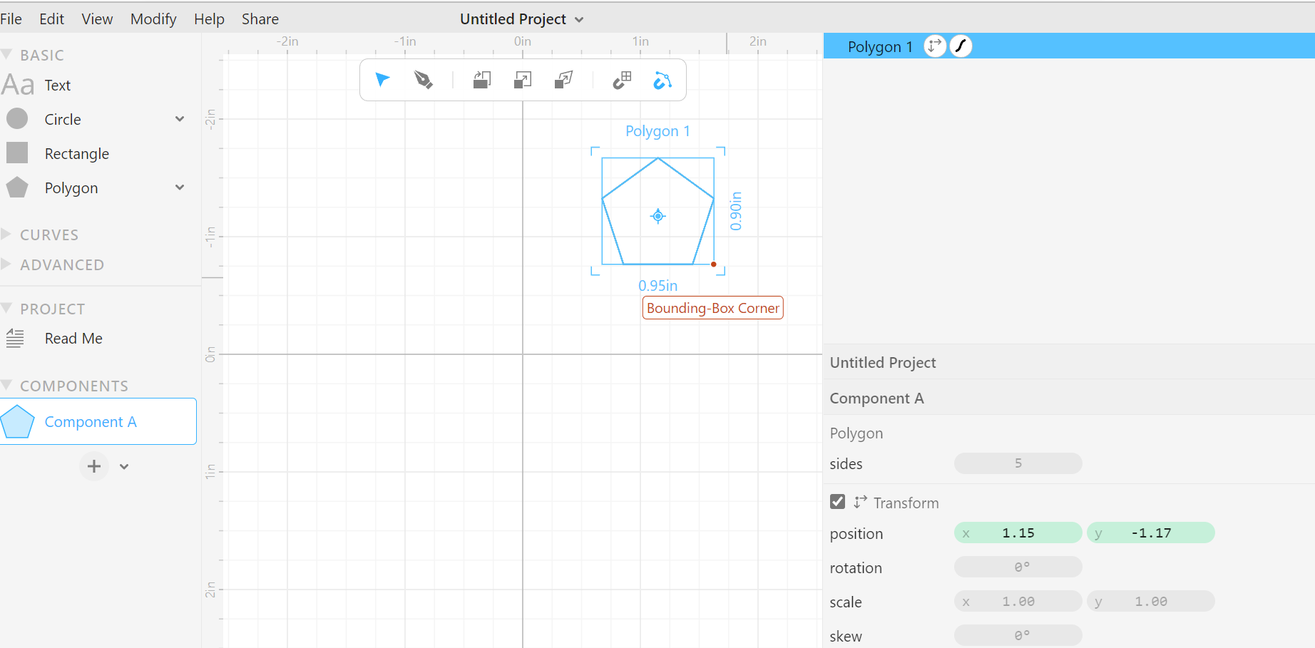
a. first I added a polygon shape.
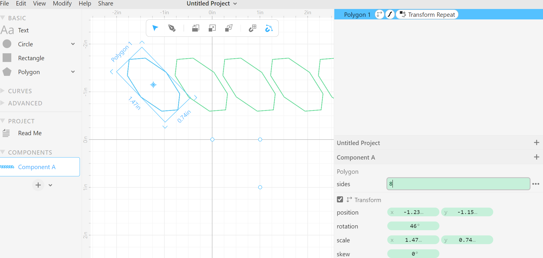
b. I changed the shape and repeated it.
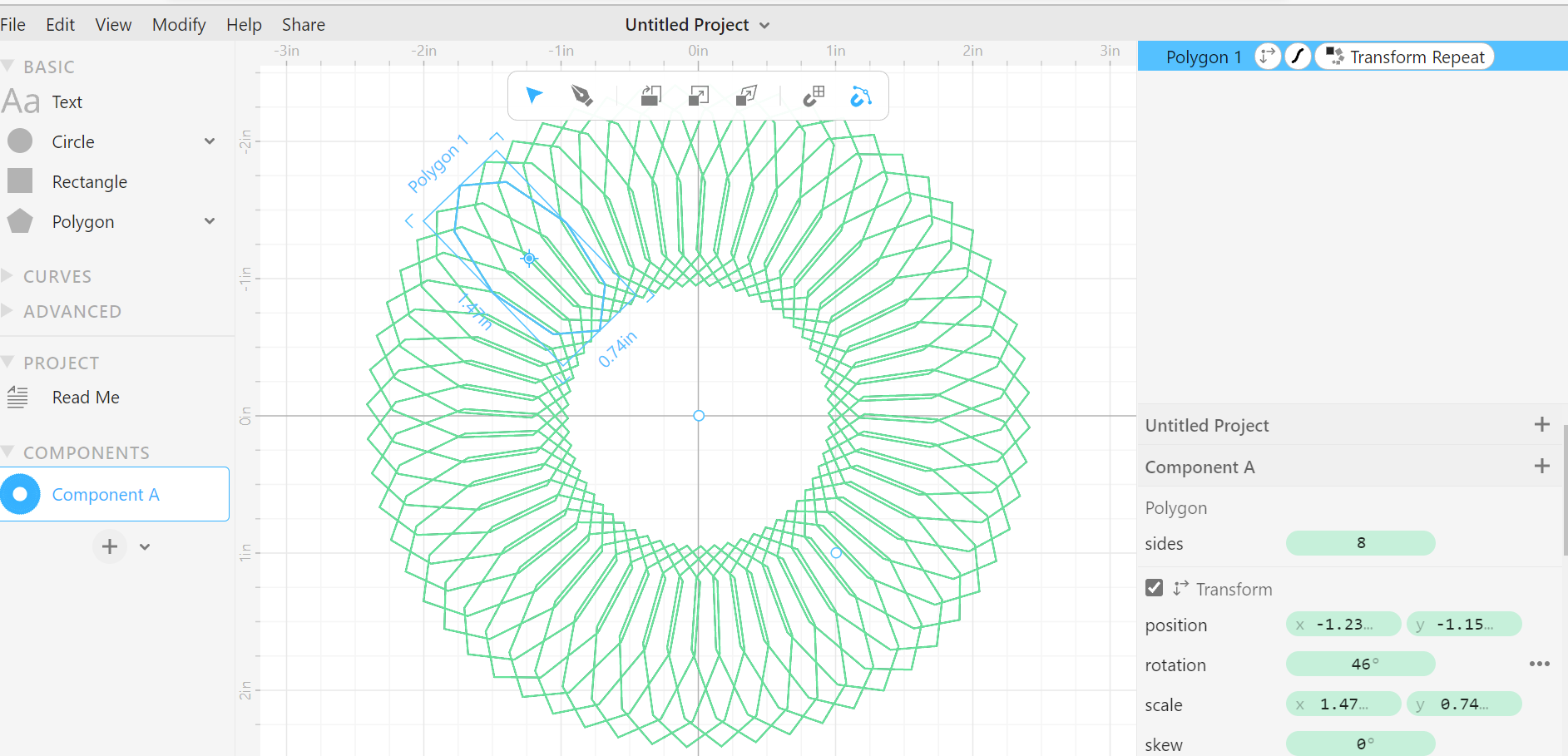
c. I rotate the shape.
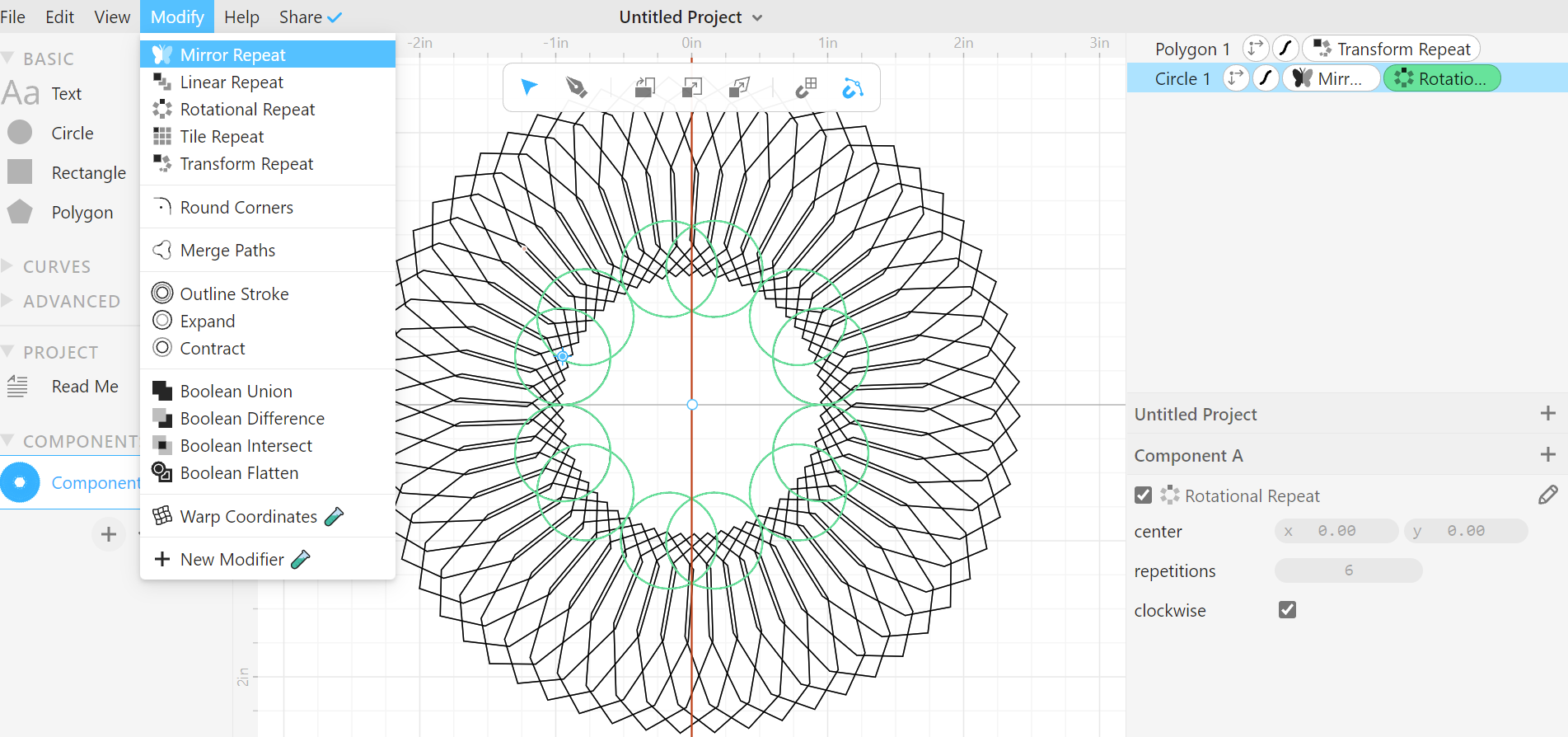
d. I added a circle and I used (Mirror repeat)
e. I made some changes and this is my final result.
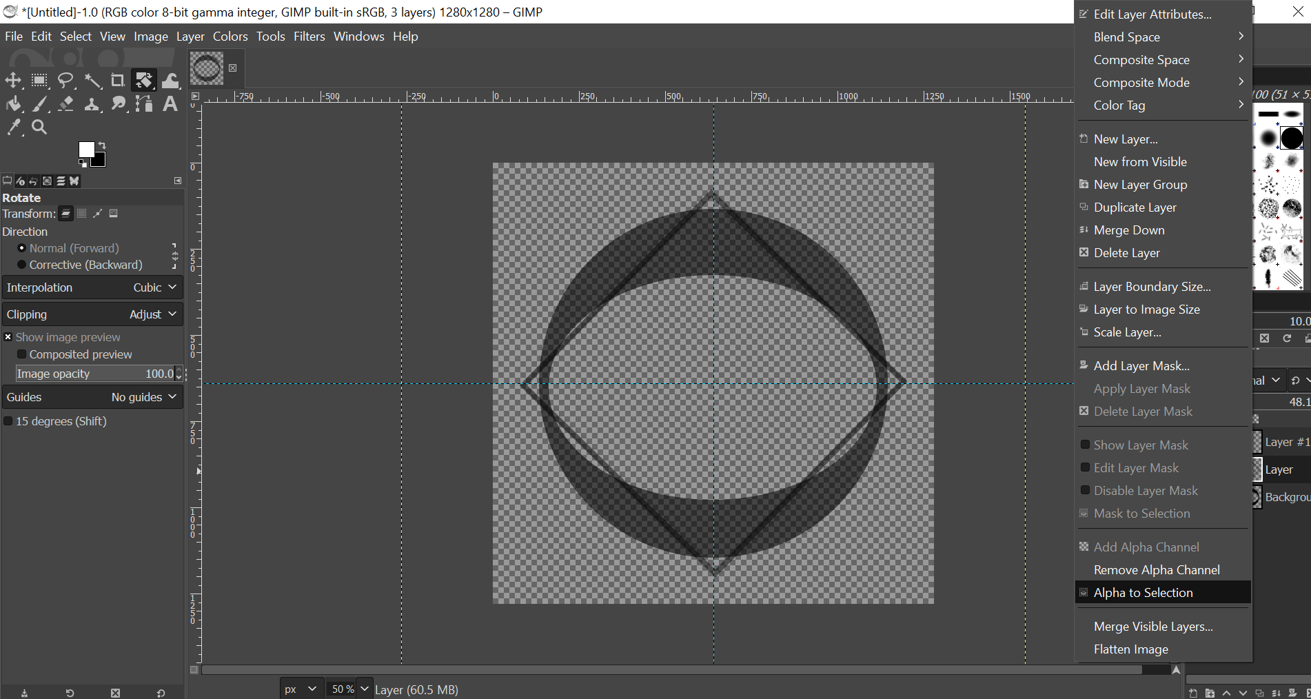
GIMP
GIMP (is a free and open-source raster graphics editor used for image manipulation (retouching) and image editing, free-form drawing, transcoding between different image file formats, and more specialized tasks.
Here is my attempt to create a simple logo:
a. First I set the image size.
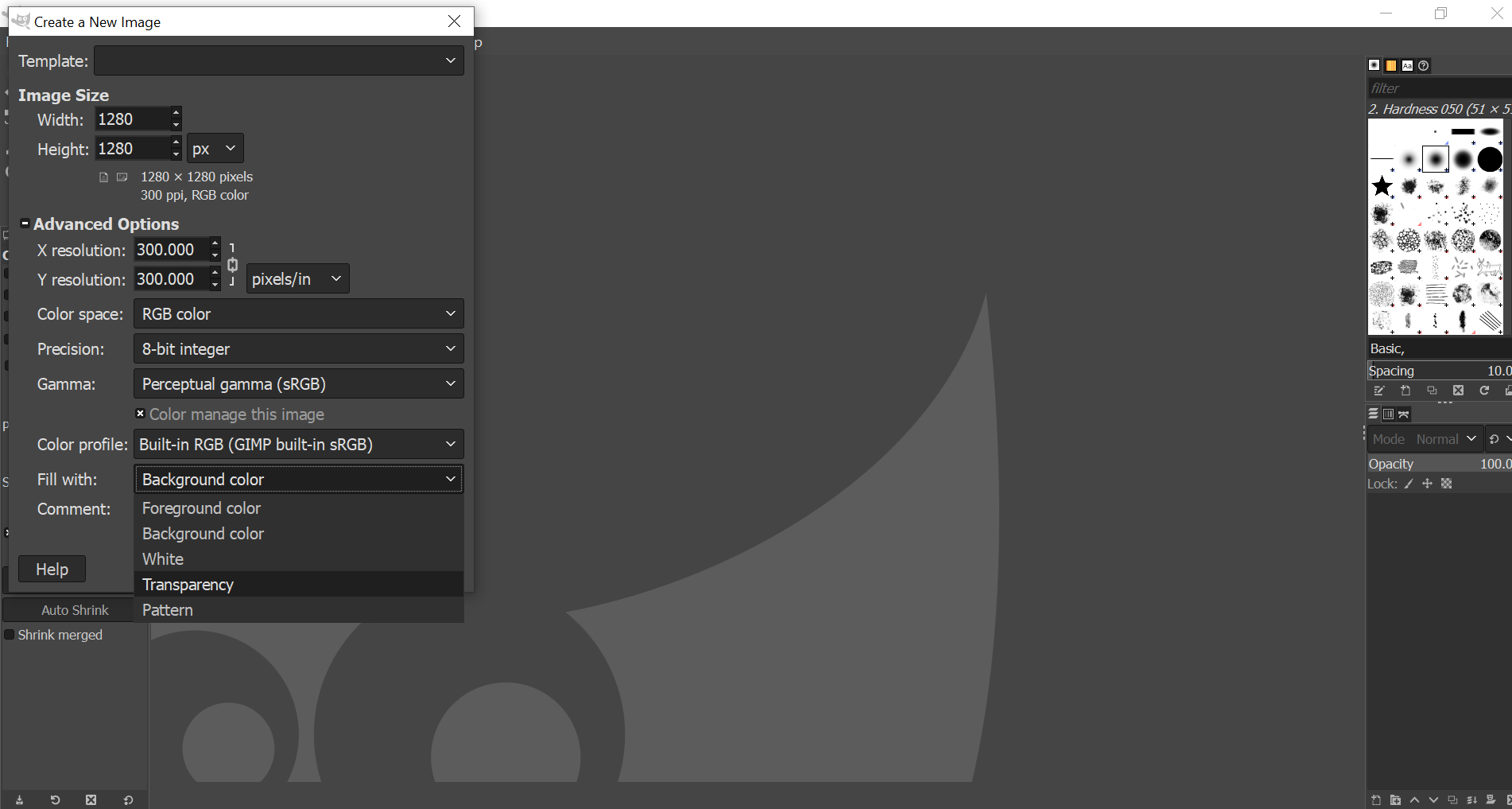
b. I insert a circle and a smaller one inside it, then deleted the middle.
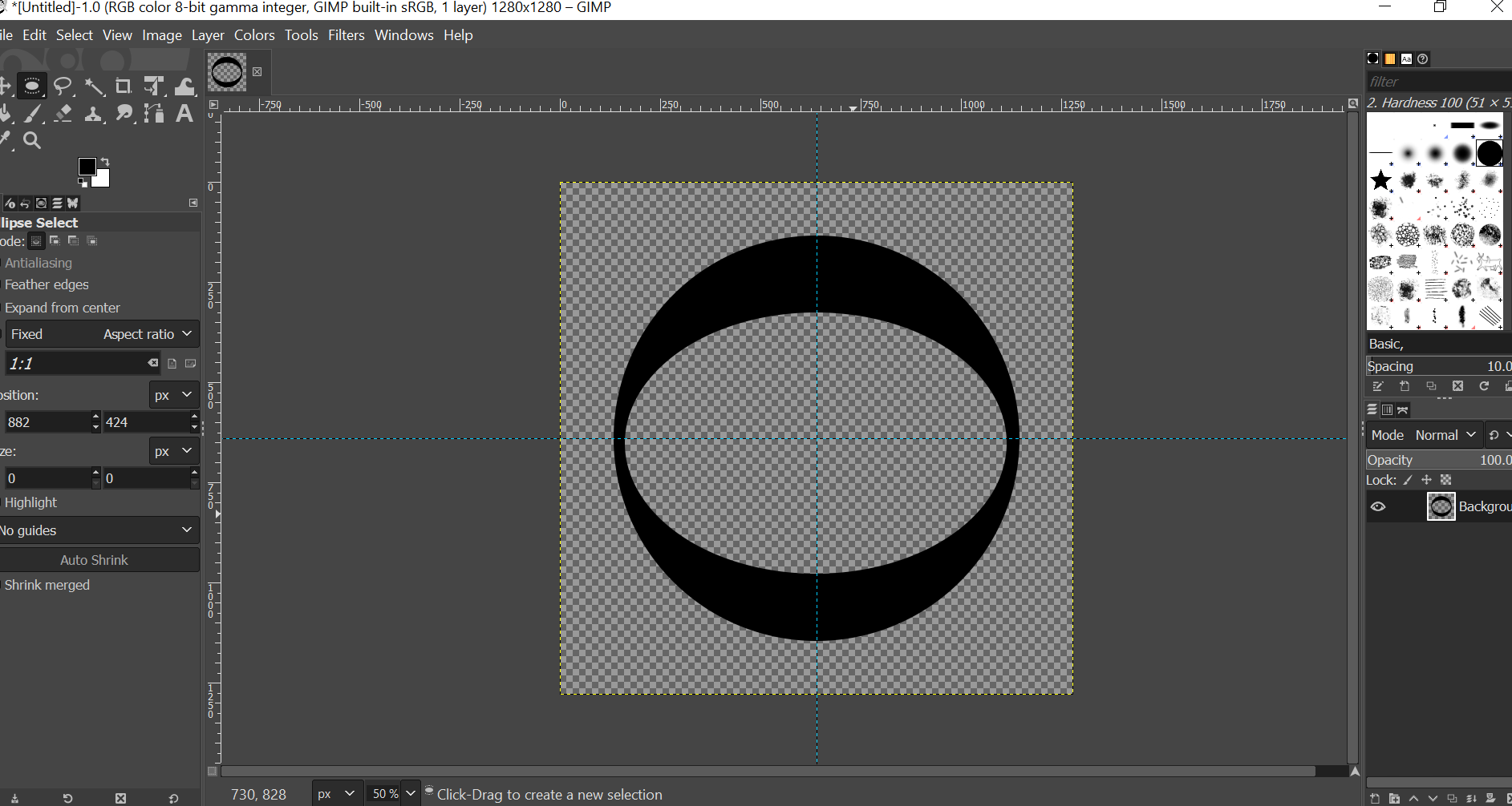
c. I set the transparency.
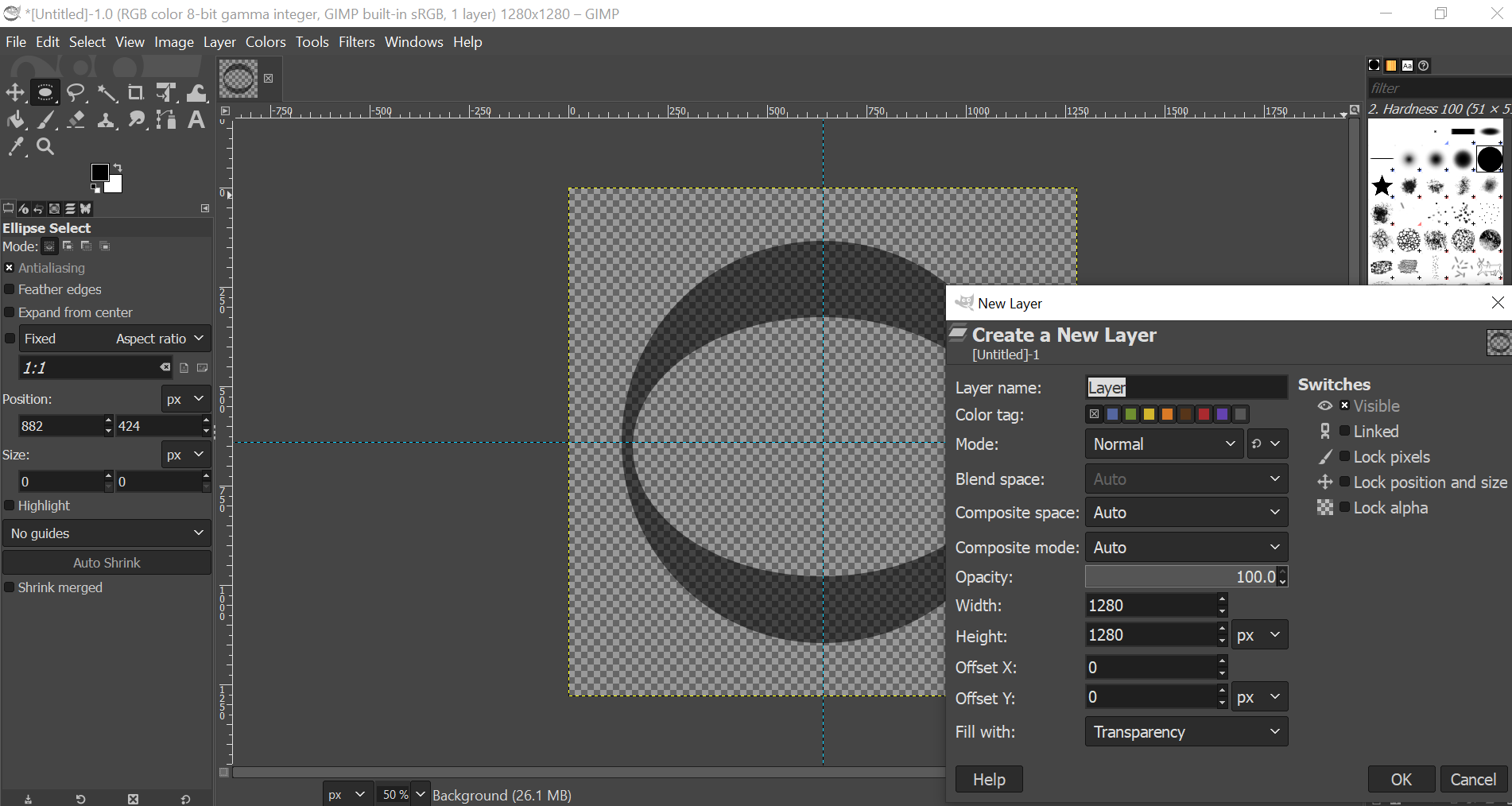
d. I added a rectangle and then I rotated it.
e. I added the text I wanted.
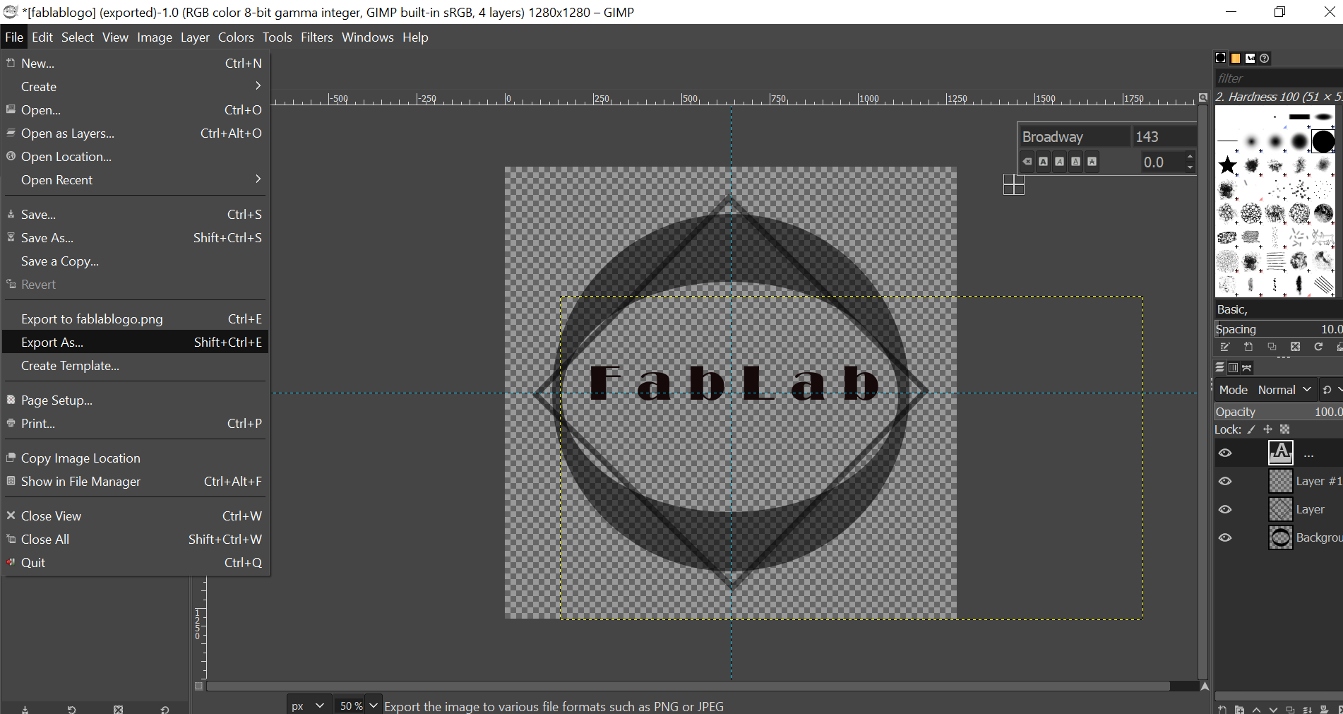
f. this is the final result.
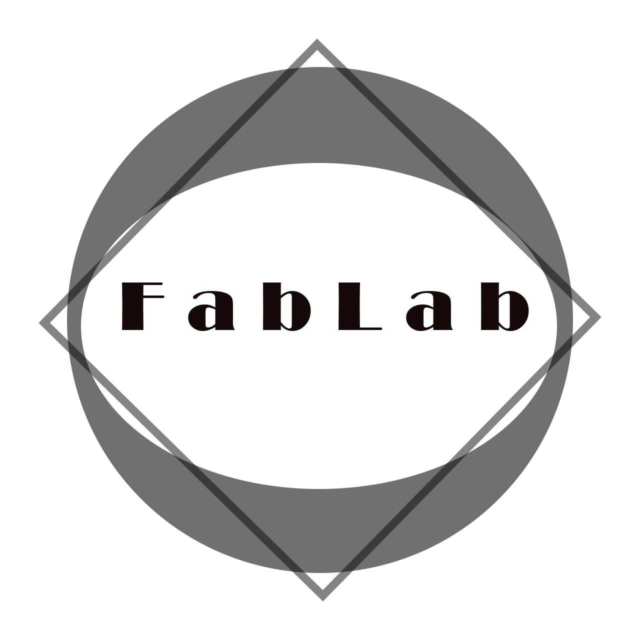
click here to see the logo in GIMP
For 3D design:
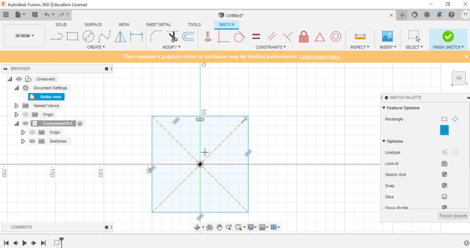
Fusion 360
Fusion 360 is a cloud-based CAD/CAM tool for collaborative product development. its combines organic shapes modelling, mechanical design and manufacturing in one comprehensive package.
I made empty box, and these are the steps:
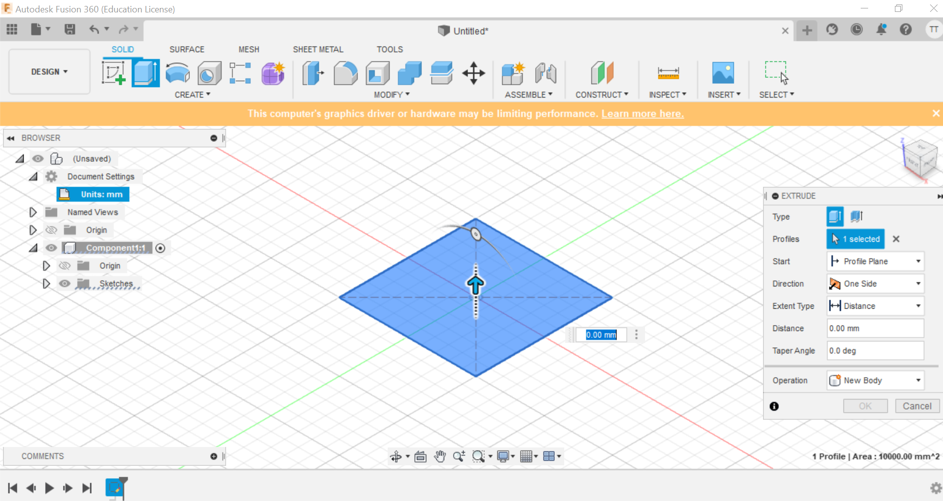
a. First I added a rectangle.
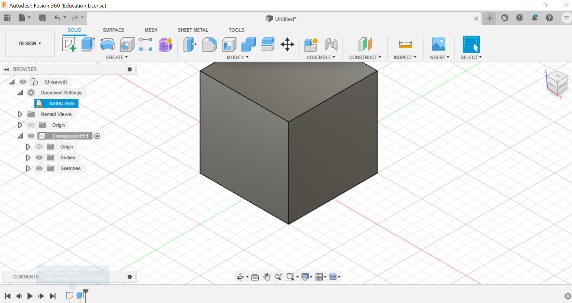
b. I extrude my rectangle to be a cube
c. I inserted a rectangle inside the one I made before a extrude it to the bottom.
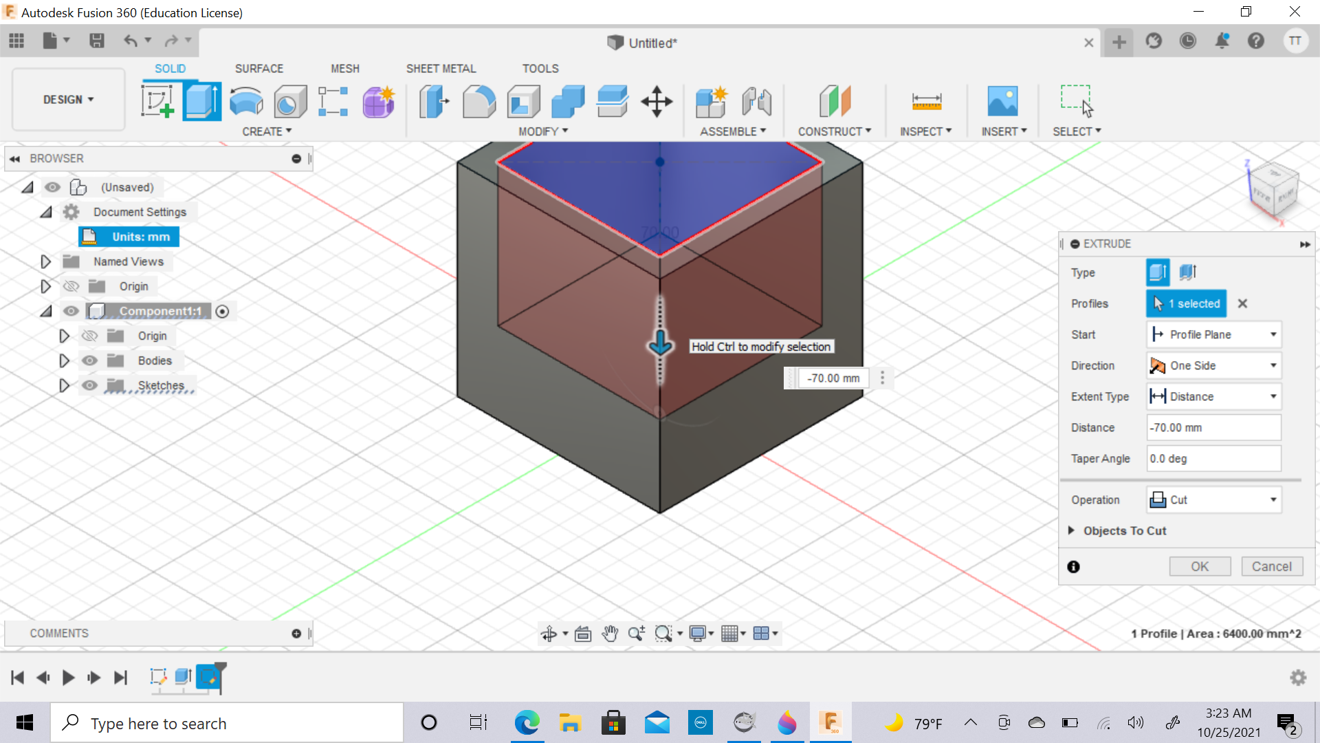
d. I set the distance to have a bottom for my box.
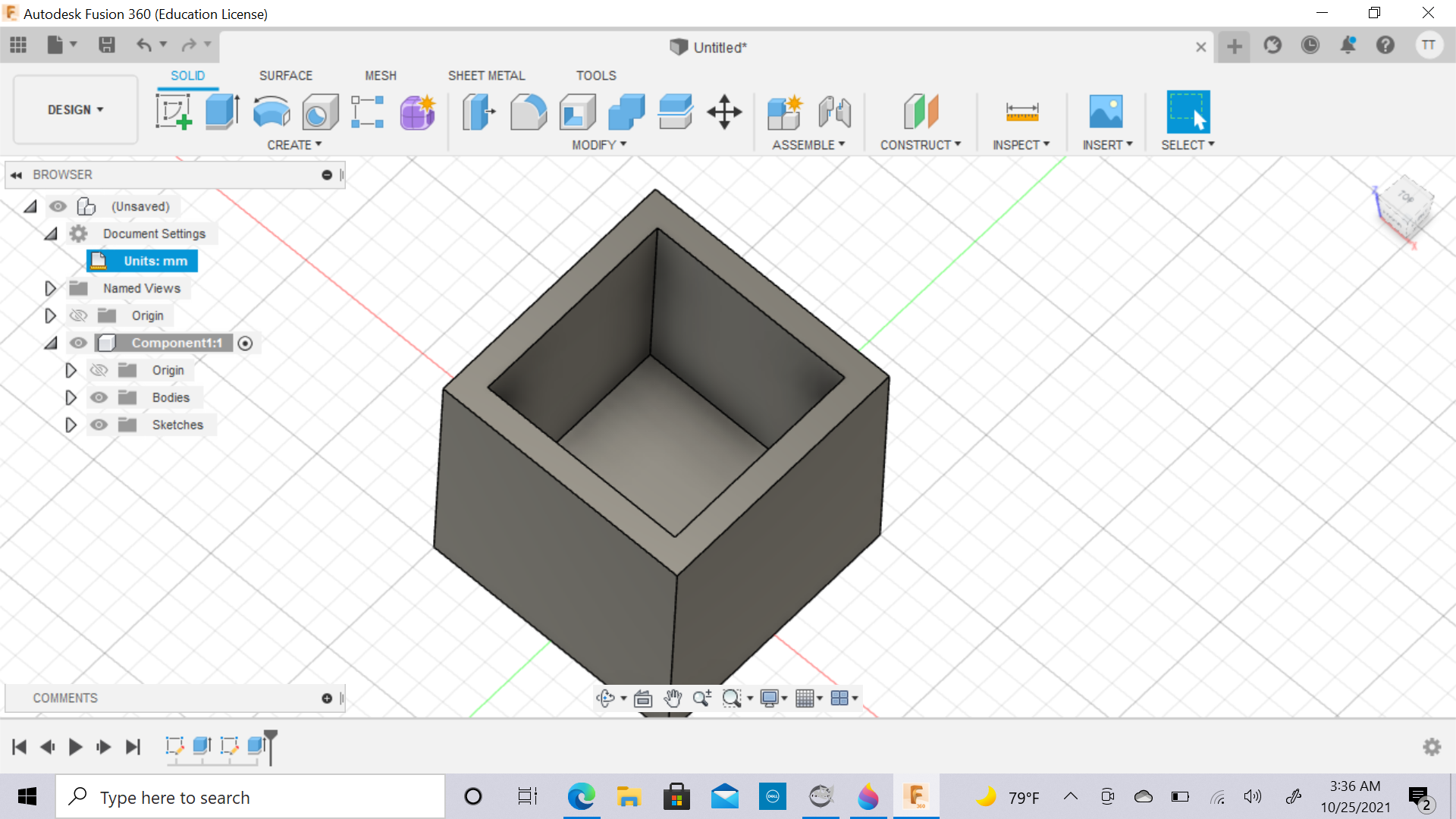
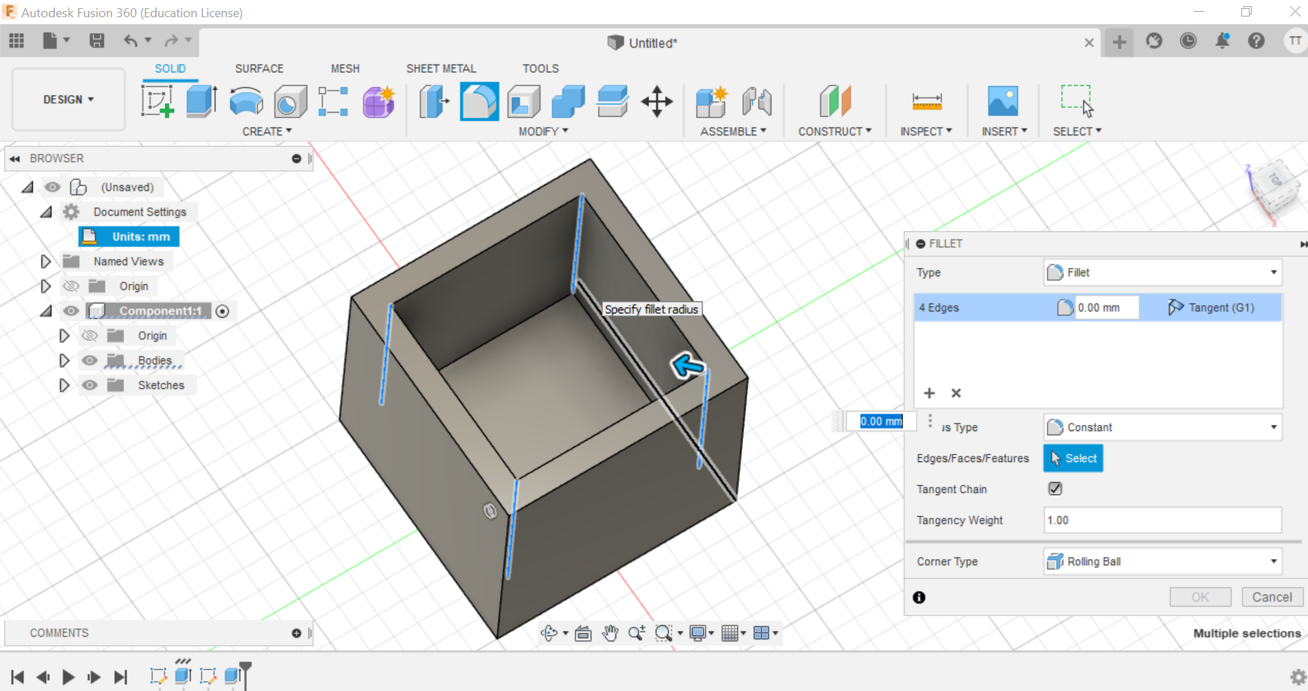
e. I smoothed the edge.
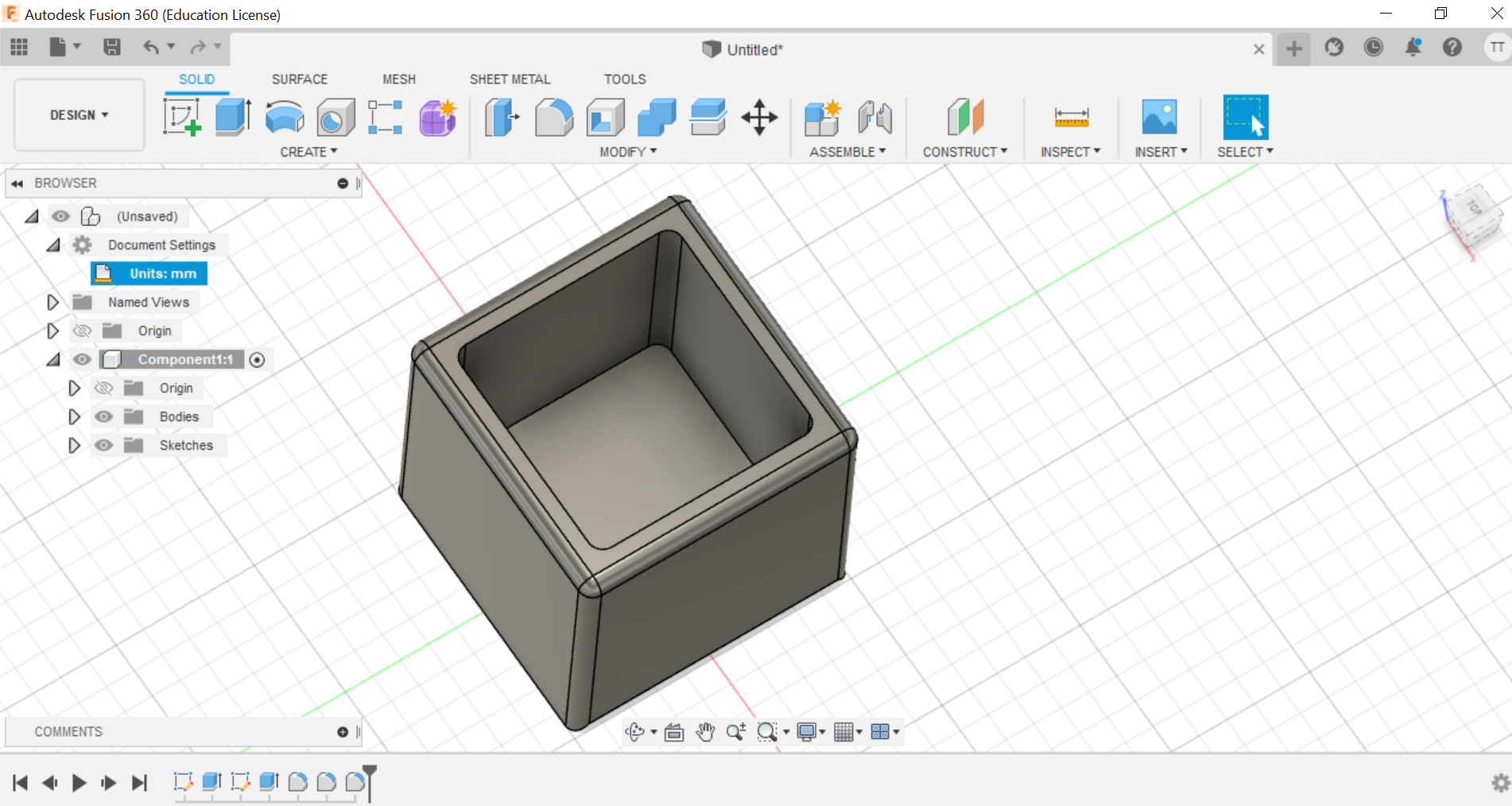
f. This is the Final result.
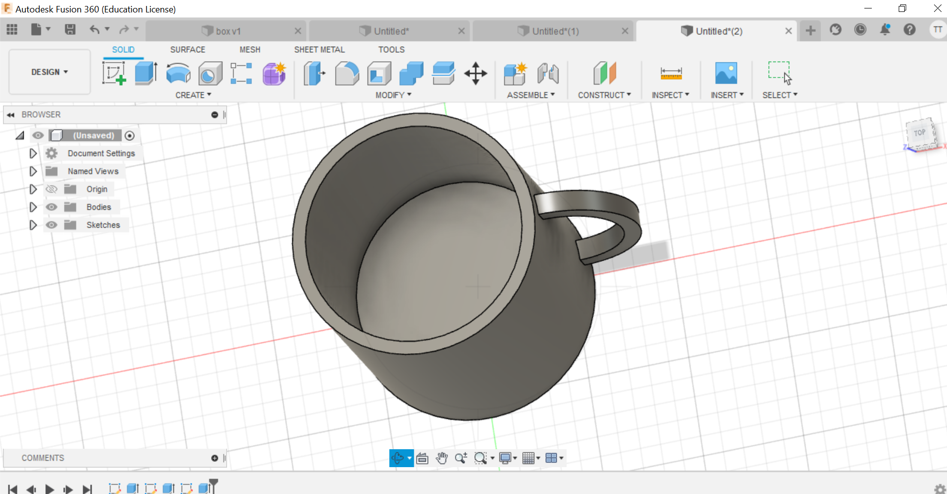
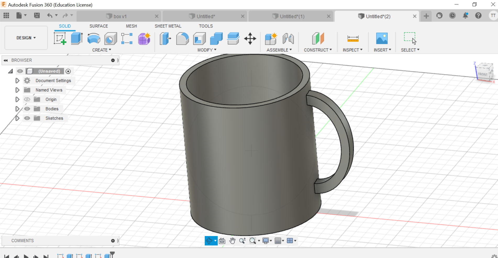
Also I made a mug, it went through the same process:
a. I created a circle, then I added an ellipse on the edge.
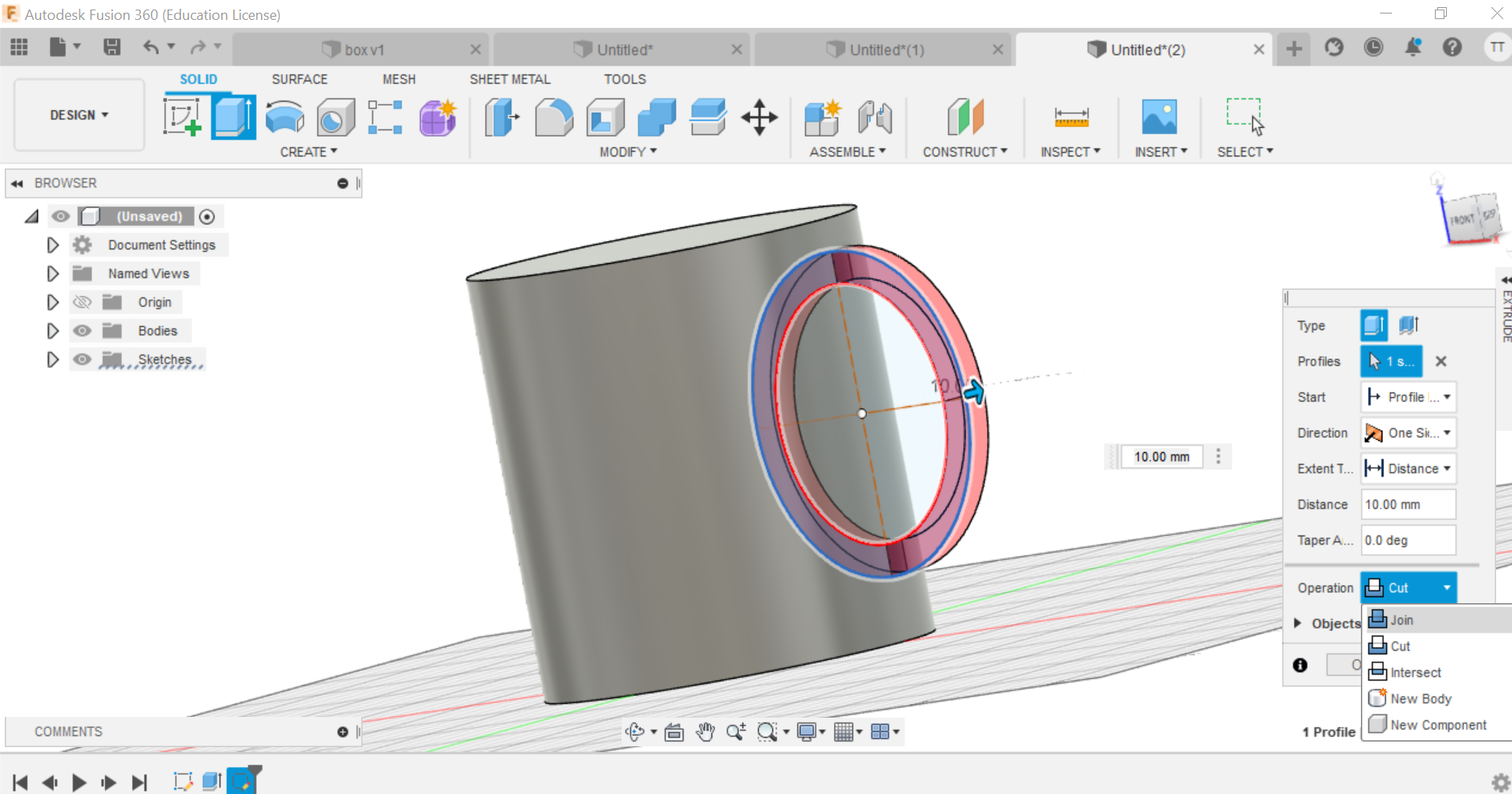
b. Then I added a circle inside the shape that I have, so I created a hollow to make it looks like a mug.
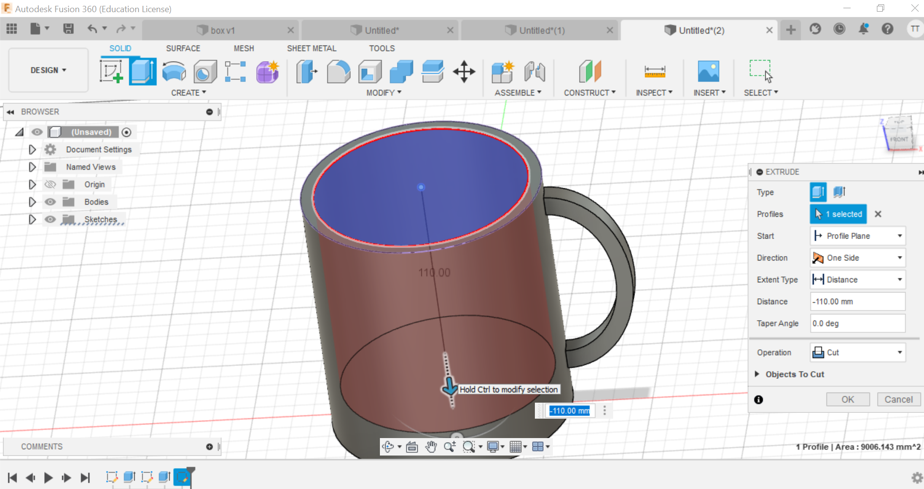
c. This is the final result.
OPENSCAD
OpenSCAD is a free software application for creating solid 3D CAD (computer-aided design) objects. It is a script-only based modeller that uses its own description language.
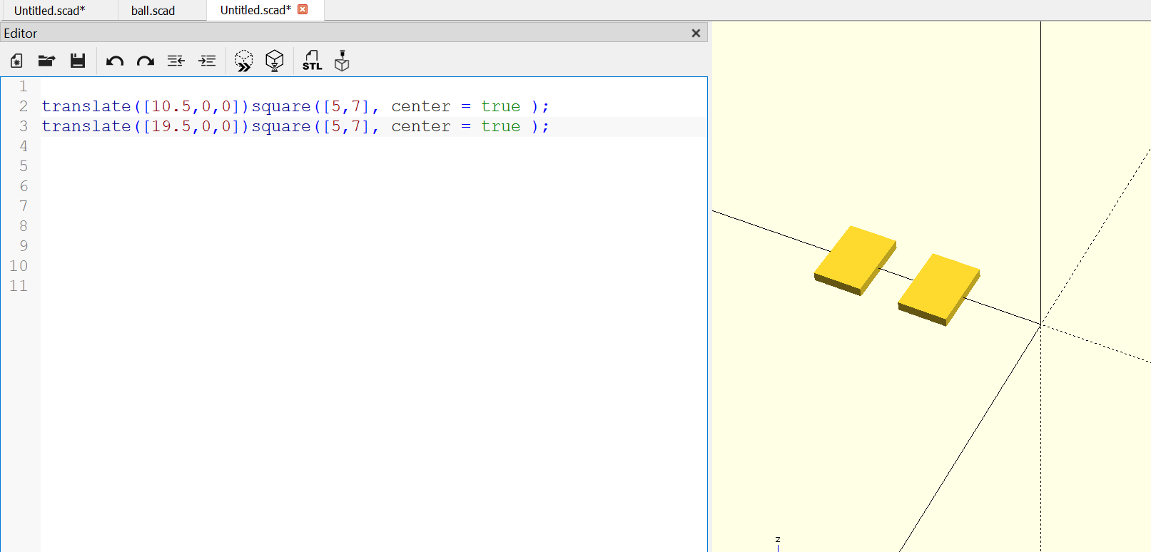
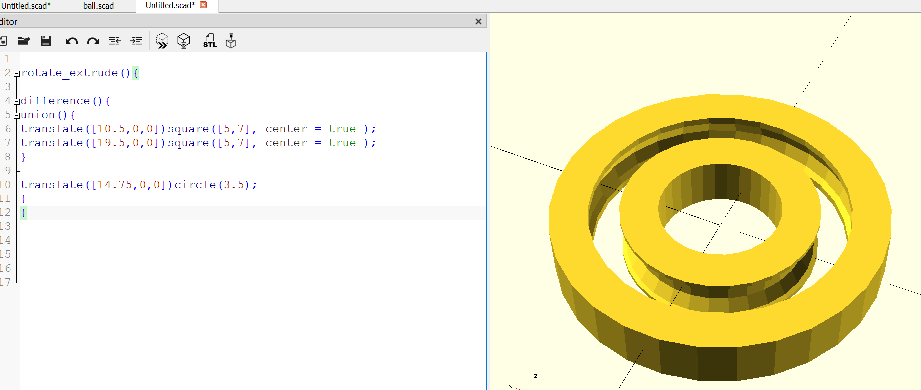
I learned how to model a bearing, and this is the steps that I followed:
a. I wrote a code for two rectangle.
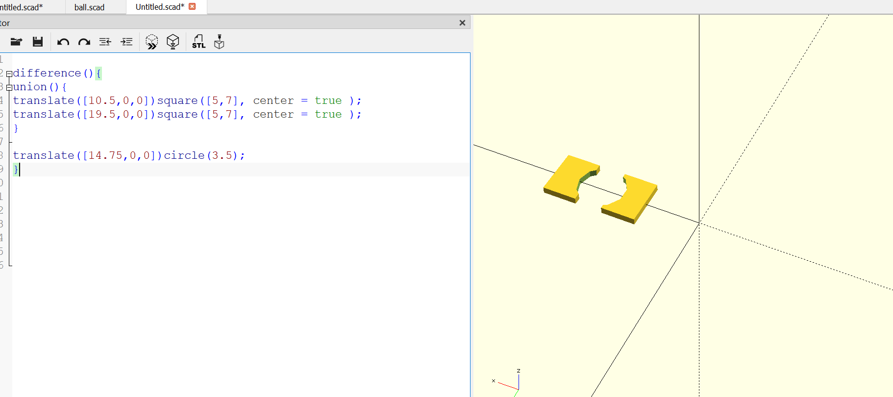
b. then I added a circle and cut the rectangle by the size of the circle.
c. then I added a depth.
d. added a loop to fill the space with small balls.
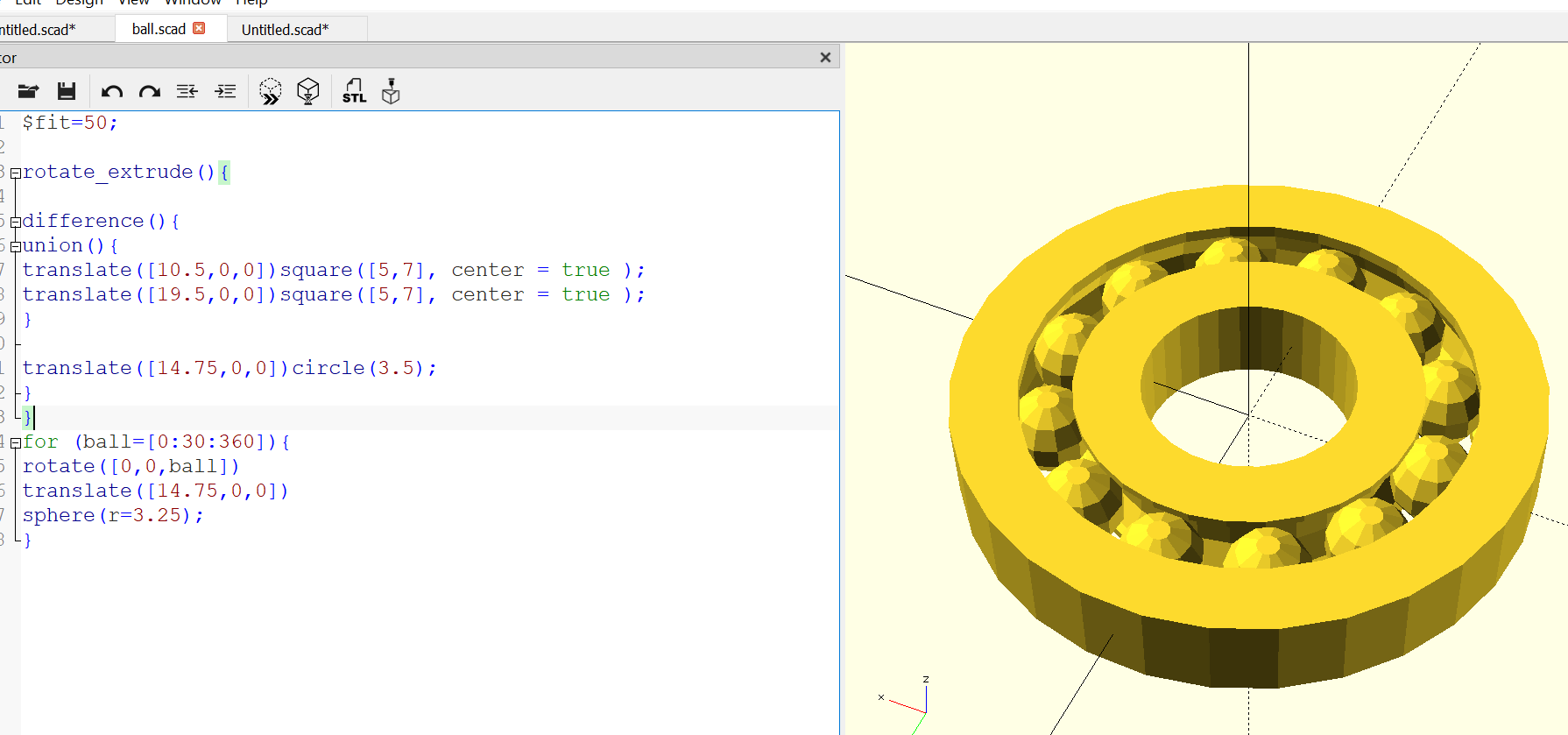
and that’s it!
This is the code that I used:
$fit=50;

rotate_extrude(){

difference(){
union(){
translate([10.5,0,0])square([5,7], center = true );
translate([19.5,0,0])square([5,7], center = true );
}

translate([14.75,0,0])circle(3.5);
}
}
for (ball=[0:30:360]){
rotate([0,0,ball])
translate([14.75,0,0])
sphere(r=3.25);
}
click here to see the code on openSCAD
This is another code to create a Lego block:
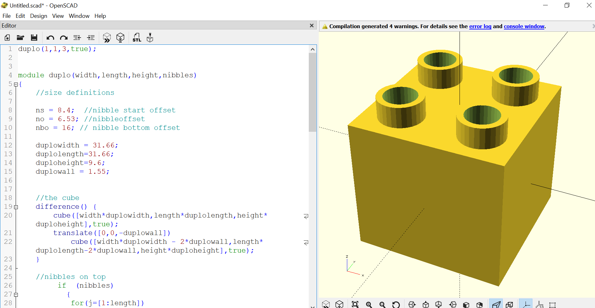
duplo(1,1,3,true);


module duplo(width,length,height,nibbles)
{
    //size definitions

    ns = 8.4;  //nibble start offset
    no = 6.53; //nibbleoffset
    nbo = 16; // nibble bottom offset

    duplowidth = 31.66;
    duplolength=31.66;
    duploheight=9.6;
    duplowall = 1.55;


    //the cube
    difference() {
        cube([width*duplowidth,length*duplolength,height*duploheight],true);
        translate([0,0,-duplowall])
            cube([width*duplowidth - 2*duplowall,length*duplolength-2*duplowall,height*duploheight],true);
    }

    //nibbles on top
         if  (nibbles)
           {
            for(j=[1:length])
        {
            for (i = [1:width])
            {
                translate([i*ns+(i-1)*no,j*ns+(j-1)*no,6.9+(height-1)*duploheight/2]) duplonibble();
                translate([i*-ns+(i-1)*-no,j*ns+(j-1)*no,6.9+(height-1)*duploheight/2]) duplonibble();
                translate([i*ns+(i-1)*no,j*-ns+(j-1)*-no,6.9+(height-1)*duploheight/2]) duplonibble();
                translate([i*-ns+(i-1)*-no,j*-ns+(j-1)*-no,6.9+(height-1)*duploheight/2]) duplonibble();
            }
        }
            }

    //nibble bottom
    for(j=[1:length])
    {
        for (i = [1:width])
        {
            translate([(i-1)*nbo,(j-1)*nbo,0]) duplobottomnibble(height*duploheight);
            translate([(i-1)*-nbo,(j-1)*-nbo,0]) duplobottomnibble(height*duploheight);
            translate([(i-1)*-nbo,(j-1)*nbo,0]) duplobottomnibble(height*duploheight);
            translate([(i-1)*nbo,(j-1)*-nbo,0]) duplobottomnibble(height*duploheight);
        }
    }
=
    difference()
    {
        union()
        {
            for(j=[1:length])
            {
                for (i = [1:width])
                {
                    translate([0,j*ns+(j-1)*no,0 ]) cube([width*duplowidth,1.35,height*duploheight],true);
                    translate([0,j*-ns+(j-1)*-no,0 ]) cube([width*duplowidth,1.35,height*duploheight],true);
                    translate([i*ns+(i-1)*no,0,0 ]) cube([1.35,length*duplolength,,height*duploheight],true);
                    translate([i*-ns+(i-1)*-no,0,0 ]) cube([1.35,length*duplolength,height*duploheight],true);
                }
            }
        }
        cube([width*duplowidth - 4*duplowall,length*duplolength-4*duplowall,height*duploheight+2],true);
    }
}


module duplonibble()
{
    difference() {
        cylinder(r=4.7,h=4.5,center=true,$fs = 0.01);
        cylinder(r=3.4,h=5.5,center=true,$fs = 0.01);
    }
}
click here to see the code on openSCAD