3. Computer-Controlled Cutting
During this week we learned how to use various computer-controlled technologies that allow for the cutting of materials. This enables the design and production of various shapes on all sorts of materials.
Laser Cutting Machine
What x How?
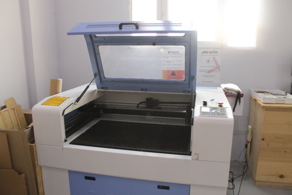
Figure 1: Laser Cutting Machine
The laser cutting machine available in the lab is a CO2 based machine that focuses a jet of CO2 gas laser beam onto the desired material dissipating the material on the path set by the design. It is able to cut the material into the desired shape. The material is placed on a bed that is 600x900mm. Furthermore, the laser cutting machine can be used to score as well as engrave a material besides cutting right through it. Below is a picture of one of the available laser cutter machines available at the lab:
Safety x Points
In order to operate the machine safely, some safety items must be adhered to and taken into account when working with the machine.
- Ensure that the guard door is closed when the machine is running.
- Ensure appropriate the laser is set to an appropriate speed and power level depending on the material and design used.
- Ensure that a safe distance is kept away from the machine when it is running
- Ensure that you do not look at the laser directly when it is running.
- Ensure that the correct material is used and to be way of prohibited materials that could damage the machine, the material, or the surroundings.
- In the case of an emergency, press the ‘Emergency Stop’ button, then isolate the power, stop the air pump and smother any flame (if applicable) using the safety fire blanket.
List x of x materials
The table below summarizes the list of materials that are commonly used in the laser cutting machine as well as some of the prohibited materials:
| Material | Can be used? |
|---|---|
| Acrylic | Yes |
| Cardboard | Yes |
| Plywood | Yes |
| MDF | Yes |
| Paper | Yes |
| Fabric | Yes |
| Leather | Yes |
| Rubber | Yes |
| PVC | No |
| ABS | No |
| Polycarbonate | No |
| Polystyrene/Polypropylene Foam | No |
| HDPE | No |
| Coated Carbon Fiber | No |
| Pros | Cons |
|---|---|
| No Tooling required | Can be limited by material type and thickness |
| Can cut complex designs | High upfront cost |
| Very precise (sub millimeter) | High power consumption |
| Very quick | Produces fumes |
| Can be significantly automated | |
| High quality, low material burr |
Calibration x Fit
To effectively use the laser cutting machine, both the power and speed settings must be adjusted depending on the material and design used. Moreover, the distance between the laser and the material needs to be calibrated to maximize the focus of the laser for a precise and deep cut. Hence, we were given an assignment to narrow down the precise distance required. This involved the use of an acrylic board placed as a ramp and running the laser through it. This is demonstrated in the picture below:
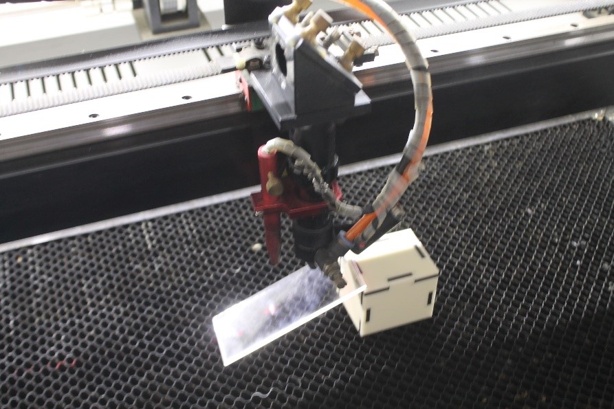
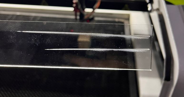
Figure 2: Laser Distance Calibration - Slope
Using the acrylic slab, the laser was made to cut a horizontal line along it. This would etch the acrylic and different focus levels as the distance varies, making it clear at which point the laser was focused the most. Hence, the exact distance of the greatest laser focus can be calculated. To do this we simply deducted the initial Z position of the bed from the final position as we increased the height to touch the slab at exactly the point of the greatest focus.
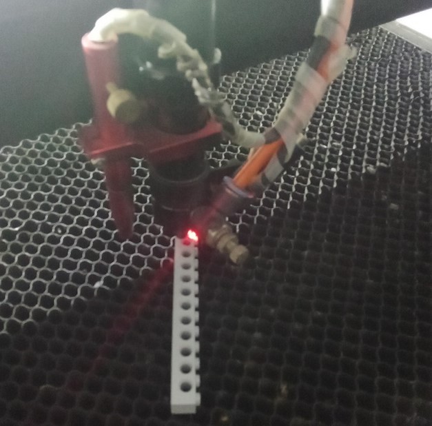
The focal point was determined to be approximately 8mm. Which is conveniently the same thickness as some Lego pieces. Thus, they are commonly used to ensure the gap between the laser and the material is 8mm to ensure the correct focal point is set.
While the machine was calibrated correctly, the correct fit for different parts needed to be ensured. To do that the tolerance the machine produces had to be measured. To do this a simple cardboard cut-out with multiple legs was modelled, the idea is that each leg would measure 0.5mm less than the previous one. And by cutting two of these cardboard cut-outs, the legs can be fit into each other to determine which would produce the perfect tight fit. The cut-out can be seen in the picture below:
(INSERT PICTURE - Object Missing)
After trying out different combinations, it was determined that a tolerance of -0.1mm created the perfect fit. So, the conclusion was that holes that were created using the laser cutting machine made for press fit joints were to be made 0.1mm smaller to ensure a perfect fit.
Design x Import
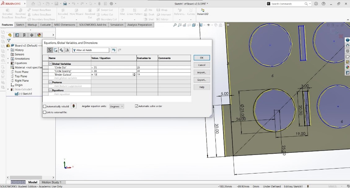
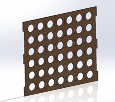
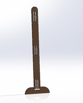
Inspired by different laser cut designs, I set out to design the Connect-Four game. I designed a 3D model of all the different parts to ensure that everything fits perfectly. Several components were designed for the game, this includes: the board, frame, binder, and base. However, it is important to note that since the design had some repeating patterns, parametric equations were used to handle this. They ensured that any change required in measurement could be easily modified in the global variable table which would automatically adjust all the values. This can be seen in the picture below which demonstrates these changes:
As seen in the pictures above and below the model was designed using Solidworks:
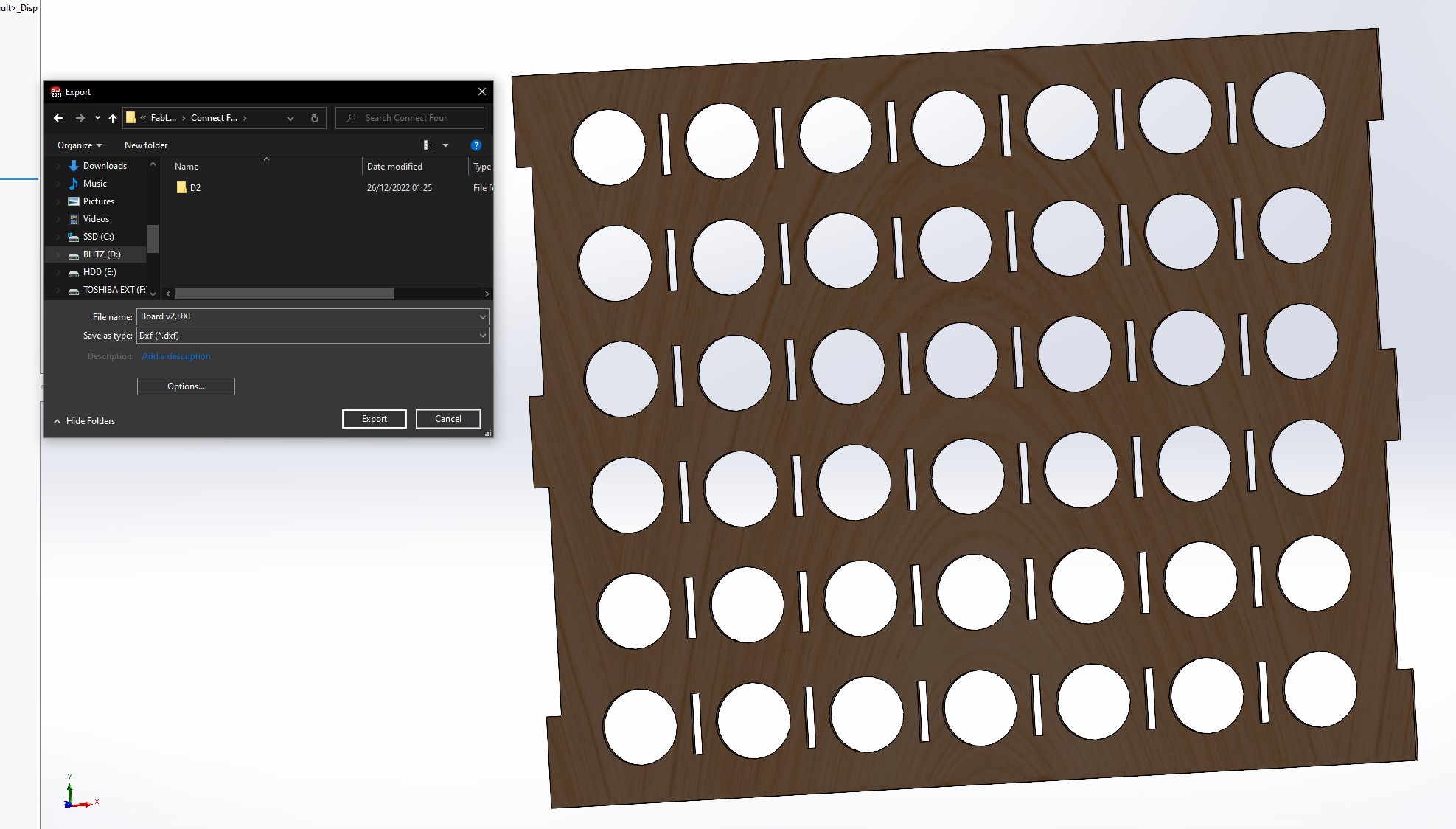
After designing the components on Solidworks, they were then saved in the DXF format as demonstrated in the picture below:
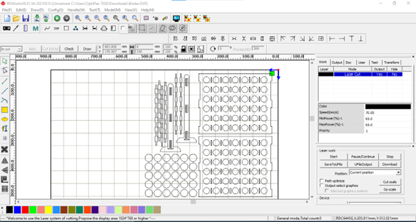
The DXF files are then imported to RDWorks which is a software for laser cutting machines which aids in importing to the design to the machine as well as controlling the movement of the laser, speed, power and other variables. The designs were imported, and some duplicated as required by the design itself. Then the power and speed were adjusted to 65W and 70mm/s as was determined to be suitable by the instructors and through test trials. This can be seen in the picture below:
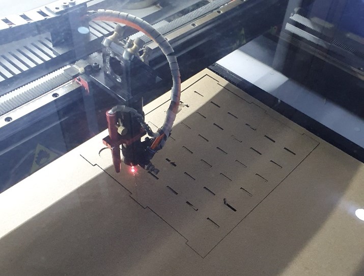
Following that the laser cutting machine was set to cut out the design. This was done by first downloading the file through the software. Then on the machine, ‘File’ was clicked to selected the specific file sent to the machine. Afterwards the origin point is set by moving the arrows on the machine until the laser was at the desired start point and then clicking the ‘Origin’ button. Finally, once the cardboard has been correctly placed, and other safety points ensured, the green ‘Start’ button is clicked. Below is a picture of the laser cutting machine at work, cutting the board:
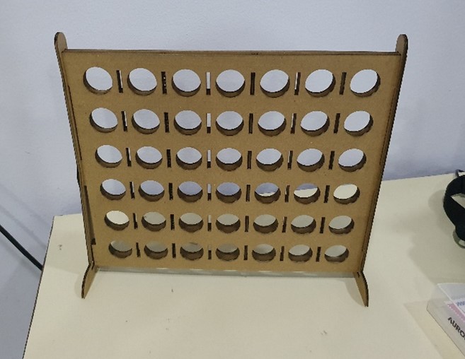
The final product was then assembled together just like the assembly done on Solidworks. This resulted in the final product shown below:
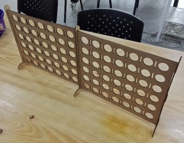
Furthermore, due to the parametric nature of the design, it can also be extended to create some interesting patterns and shapes that can be used for decoration. Below is an example of another variation on the design that has decorative applications:
Cricut
What x How?
Cricut is a brand of cutting machine that is used to cut a variety of materials such as paper, cardstock, vinyl, and fabric. The machine works by using a small, sharp blade to precisely cut out shapes and designs according to a digital design file. Cricut machines are often used for crafts and DIY projects, such as creating custom invitations, labels, and decals.
To use a Cricut machine, the user first selects a design or creates their own using the Cricut Design Space software. The design is then uploaded to the machine and the user selects the type and size of material they will be cutting. The machine uses a small blade to follow the path of the design, cutting through the material with precise accuracy.
Idea x Design
For my individual design idea, I made a simple text design with a gear logo symbolizing my mechanical engineering background. I did this via Adobe Illustrator which resulted in the design on the right: 
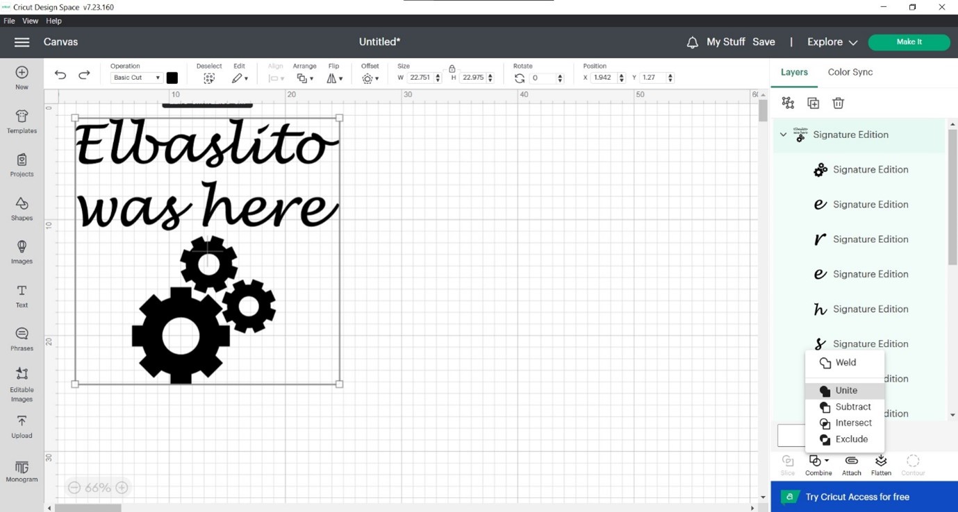
Then using the Cricut Design Space software, the design was imported and the settings were configured accordingly. Since the design had multiple objects that were separated, they had to be joined using the ‘combine’ button with the unite feature, in the design space:
Once the design is finalized, the ‘Make’ button is clicked which leads you to the print preview page which demonstrates what the final cut will look like: 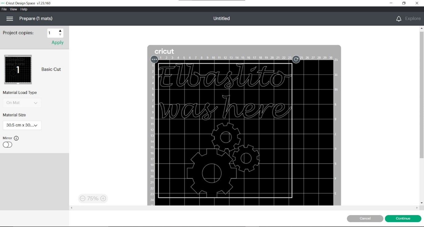
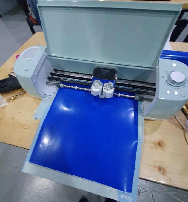
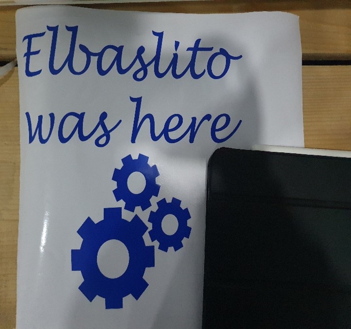
Finally, the sticker paper was loaded into the cricut, whereby the release button is clicked to allow the paper to be inserted. Once inserted properly, the button is clicked again to lock it in place. Then once locked in, the machine can be released to cut. The below pictures demonstrate this process as well as the final result including the group assignment T-Shirt:

Download x Files
You can find the links to download the design files produced below: