Final Project
Before we get down to the details of how I made my final project, here is a teaser of the final product.
Carnage X And X Devestation
So for my final project I decided to make an electric skateboard. The inspiration for this came from two sources, the first was during week 5 where we worked with the CNC wood router. I was initially going to make a skateboard using a layer of veneers placed on two molds to shape it. However, I deemed the idea to complex for a short week’s worth of an assignmennt. The second inspiration comes from an anime that I watched when I was 7 and still do, it’s called: ‘Detective Conan’. Where the main character occasionally uses an electric skateboard to help go around.
Now you might ask yourself why is he talking about an electric skateboard when the teaser picture above is clearly not a skateboard. I mean technically it could be if you’re light enough. But we’ll get to why the picture is different in a minute.
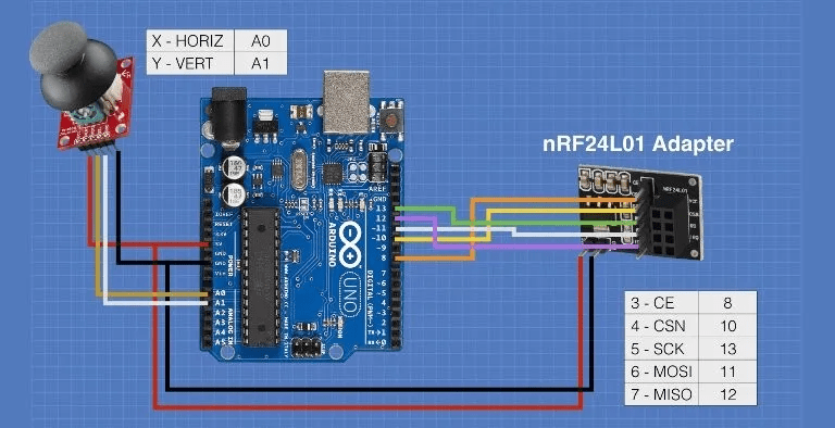
So as began working on the electric skateboard, I first tested the use of two NRF24L01 transciever modules connected to two arduino unos. By writing a simple code, I was able to send data wirelessly between the arduinos. This was so that I can send data between a remote and the skateboard so I can wirelessly control it. The code I wrote for testing purposes was to translate the movement of a joystick to moving a simple servo.
The first code for the transmitting transceiver can be seen below:
#define in1 9
#define in2 8
#define in3 6
#define in4 7

const int pingPin = 3; // Trigger Pin of Ultrasonic Sensor
const int echoPin = 4; // Echo Pin of Ultrasonic Sensor

int rotDirection = 0;
int pressed = false;
long duration, inches, cm;

void setup() {
  Serial.begin(9600);
  pinMode(in1, OUTPUT);
  pinMode(in2, OUTPUT);
  pinMode(in3, OUTPUT);
  pinMode(in4, OUTPUT);
  pinMode(pingPin, OUTPUT);
  pinMode(echoPin, INPUT);
  // Set initial rotation direction
}

void loop() {
   digitalWrite(pingPin, LOW);
   delayMicroseconds(2);
   digitalWrite(pingPin, HIGH);
   delayMicroseconds(10);
   digitalWrite(pingPin, LOW);
   duration = pulseIn(echoPin, HIGH);
   cm = microsecondsToCentimeters(duration);
   Serial.print(cm);
   Serial.print("cm");
   Serial.println();
   delay(100);

   if(cm<=20){
    digitalWrite(in1, LOW);
    digitalWrite(in2, HIGH);
    digitalWrite(in3, LOW);
    digitalWrite(in4, HIGH);
   } else{
      digitalWrite(in1, LOW);
      digitalWrite(in2, LOW);
      digitalWrite(in3, LOW);
      digitalWrite(in4, LOW);
   }
  }

long microsecondsToCentimeters(long microseconds) {
   return microseconds / 29 / 2;
}
Below is the code for the receiver:
#include <SPI.h>
#include <nRF24L01.h>
#include <RF24.h>
#include <Servo.h>
#include <math.h>

RF24 radio(9, 8); // CE, CSN pins
const byte address[6] = "00001";

Servo myservo;  // Create servo object
int xValue, yValue;
float angle;
int axis[2];

void setup() {
  myservo.attach(6);  // Attach servo to pin 9
  radio.begin();
  radio.openReadingPipe(0, address);
  radio.setPALevel(RF24_PA_MAX);
  radio.startListening();
  Serial.begin(9600); // start the serial communication
}

void loop() {
  if (radio.available()) {
    radio.read(&axis, sizeof(axis));
    xValue = axis[0];
    yValue = axis[1];
    // Print the joystick values to the serial monitor
    angle = atan2(yValue, xValue);
    Serial.print("X-axis: ");
    Serial.print(xValue);
    Serial.print("  Y-axis: ");
    Serial.print(yValue);
    Serial.print(" Angle: ");
    Serial.println(angle*100);


    // Use xValue to control the servo's position
    myservo.write(angle*100);

  }
}
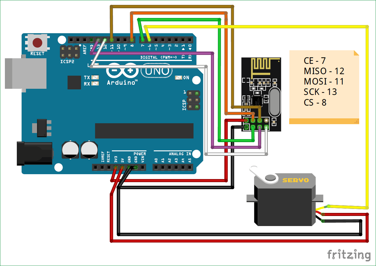
Besides these two pieces of code, enjoy a very nice looking circuit diagram of how I hooked up the transceivers to the arduinos:
And following that here is a short video showing the whole thing in action:
Once this started working, I moved on to connecting the ESC ‘Electrics Speed Controller’ to the arduino. After labelling the different cables and organizing everything I started hooking up the wires. But an important thing one should always do is to insulate all the leftover cables that are not in use. However, as an amatuer in electronics especially rated with higher voltages I did not do that. And so when I connected the 36v battery required to power the controller, two wires were pulled and managed to touch each other which created a short circuit. This resulted in a cloud of smoke and sparks flying out for miliseconds where I quickly disconnected the battery.
It was safe to say that I was not up to this level of electronics yet so I decided to switch my project as I was clearly traumitized by the events that unfolded right in front of my eyes. Something ‘I would get used to happening’ I was told.
Was all of this useless though? In a sense yes, I fried an arduino microcontroller, burned a few wires, essentially burned a 36v battery, and made the course instructors at Fablab more wary of me when it comes to electronics (which I suppose is a good thing). But it makes for some great content to fill up my documentation and make it long, I also still got to learn how to transceivers work and how to use them/code them. I learned to be careful with 36v batteries, well any battery really. I also learned that ESCs have a ton of wires and they can be crazy complicated… or I am just a beginner. It’s probably the latter.
End × And × Beginning
So with new beginnings as the title implies I decided to make........ an obstacle avoiding robot. Now the inspiration for this is more.. well lets say publishable and more awe-worthy. Back when I was in the seventh grade when I just started getting interested in the idea of robotics, I would scour the internet looking at website on website from instructable to lifehacker reading about how to build a robot using a simple microcontroller, ultrasonic sensor, and a dc motor alongside other electronics. Unfortunately for little me, online shopping was just starting to become a thing and my dad was skeptical and did not want to put his credit card information on some website, so I had no way of acquiring the electronics I wanted to build my robot. So I never got to fulfill that dream… well that is until now.
So lets dive into how I made it.
Very × Sharp × Eye
To begin my adventure, I first started with testing the ultrasonic sensor and playing with some to get it to work. Since I was going to connect it to a dc motor anyways, I figured I should write some simple code to make the motor move as long as the ultrasonic sensor doesn’t detect anything within 20cm. So I simply connected the ultrasonic sensor as well as the dc motor to the arduino, here is a picture showing the wiring diagram:
Now let me explain how the ultrasonic is connected to the arduino and how it works, it’s really quite simple, and smart actually. So you have four pins on the sensor, two for power and groud, the other two are echo and Trig. Trig essentially stands for trigger, which as the name implies is the trigger signal that pushes the ultrasonic sensor to provide a reading. The other pin echo on the other hand returns a signal which is a time output in miliseconds. Now how does this help us exactly?
To put it simply, once the ultrasonic sensor receives a trigger signal, it fires sound waves from its “eyes” the two eye looking circles. These waves propagate until they bump into something, once they do they bounce back and propagate once again until they are received by the ultrasonic sensor. In the meantime, the ultrasonic sensor starts a timer and counts how long it has been since the sound waves were fired. This is the output of the echo pin. But what do we do with this?
If you have taken any basic physics class you should know that the equation for distance is simple d = v * t. Where d = distance, v = velocity, and t is time. Now since we know the time, all we need to know is the speed to figure out the distance. Now a property of sound waves is that the speed is generally approximately constant in different mediums, and in air, the speed of sound is 343.2 metres per second. So we simply plug these values in the equation and we got the distance, woohoo! (not the sims one). But if you calculate this distance you will see that it is incorrect, and if you observe closely you will notice that the distance is actually 2x the distance. The answer behind this mystery is quite simple, it is because the soundwaves go one way to bump the object in front of them and then BACK the whole way to the sensor. So it crosses the same distance twice. Which means we simply have to divide the distance by two and we get our answer.
Now knowing all of this, I wrote a simple code to make the motor run using the ultrasonic sensor, which can be seen below:
#define in1 9
#define in2 8
#define in3 6
#define in4 7

const int pingPin = 3; // Trigger Pin of Ultrasonic Sensor
const int echoPin = 4; // Echo Pin of Ultrasonic Sensor

int rotDirection = 0;
int pressed = false;
long duration, inches, cm;

void setup() {
  Serial.begin(9600);
  pinMode(in1, OUTPUT);
  pinMode(in2, OUTPUT);
  pinMode(in3, OUTPUT);
  pinMode(in4, OUTPUT);
  pinMode(pingPin, OUTPUT);
  pinMode(echoPin, INPUT);
  // Set initial rotation direction
}

void loop() {
   digitalWrite(pingPin, LOW);
   delayMicroseconds(2);
   digitalWrite(pingPin, HIGH);
   delayMicroseconds(10);
   digitalWrite(pingPin, LOW);
   duration = pulseIn(echoPin, HIGH);
   cm = microsecondsToCentimeters(duration);
   Serial.print(cm);
   Serial.print("cm");
   Serial.println();
   delay(100);

   if(cm<=20){
    digitalWrite(in1, LOW);
    digitalWrite(in2, HIGH);
    digitalWrite(in3, LOW);
    digitalWrite(in4, HIGH);
   } else{
      digitalWrite(in1, LOW);
      digitalWrite(in2, LOW);
      digitalWrite(in3, LOW);
      digitalWrite(in4, LOW);
   }
  }

long microsecondsToCentimeters(long microseconds) {
   return microseconds / 29 / 2;
}
Below is a short video demonstrating all of this in action:
(INSERT VIDEO - cannot find video for some reason but I know it exists)
Combination × And × Evolution
Now that I know how to wire the motors and the ultrasonic sensor to the microcontroller, I decided to focus on the design of the chassis to hold all the electronics together. But first, wait hold up. Quick interlude… I did then test connecting the motor to an H-Bridge (L298N) which essentially acts as a motor controller, allowing me to control the direction and speed of the motor while conveniently allowing me to control up to two motors AND output some voltage (which spoilers, we will use to power some other stuff).
Okay back to chassis design. So I could have simply found a design of a chassis for an obstacle avoiding robot off of google, downloaded that, cut it out and boom chassis done. But I’m not amateur, let me tell you that. I’m an amateur with a few extra steps, that’s right.
So I popped open old Solidworks, my trusty mechanical design software and got to drawing. I wanted to make a two layer chassis that would hold all the electronics and motors in place, I also wanted the chassis to hold everything perfectly with perfectly cut holes to mount everything. And ever the ambitious one I am, I also created some extra holes which are for future upgrades for this project. Of course these have two purposes, one for unplanned upgrades with convenient holes just to help, and then there are intended upgrades where I purposely created specific holes for these upgrades. These include a mount for a servo to hold an ultrasonic sensor that would scout out the area. There are also extra mounting holes for additional ultrasonic sensor mounts.
So as mentioned before, I’m simply an amateur with extra steps. So naturally, getting the chassis design right from the first time was not going to happen. Basel you can keep dreaming but just like a code with no bugs from the first run, a design that is flawless on the first run is only a trojan horse waiting to release all the failures within, running on nothing but tape and sheer willpower.
The previous paragraph was just to prepare you to see the number of design iterations there were:
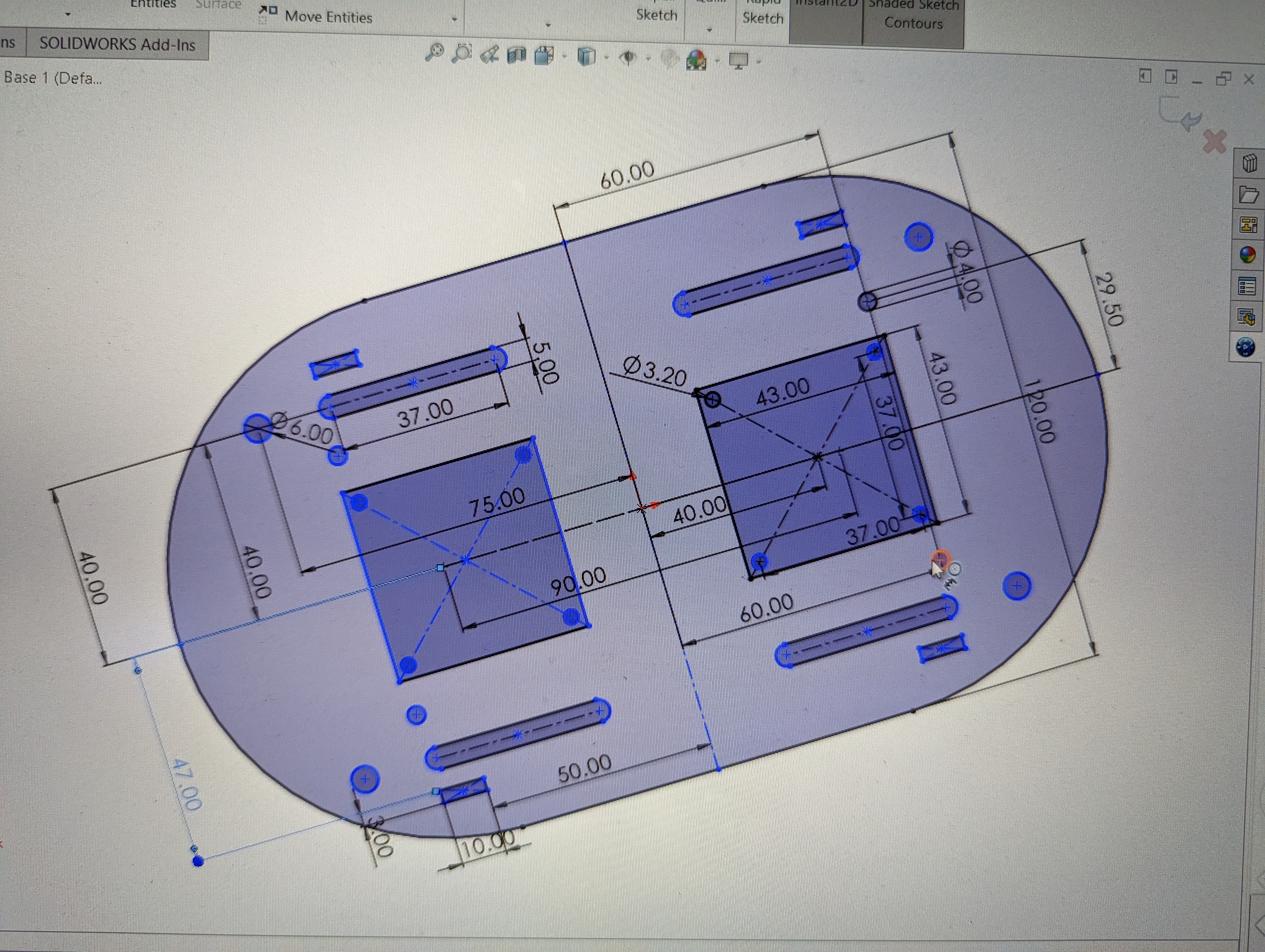
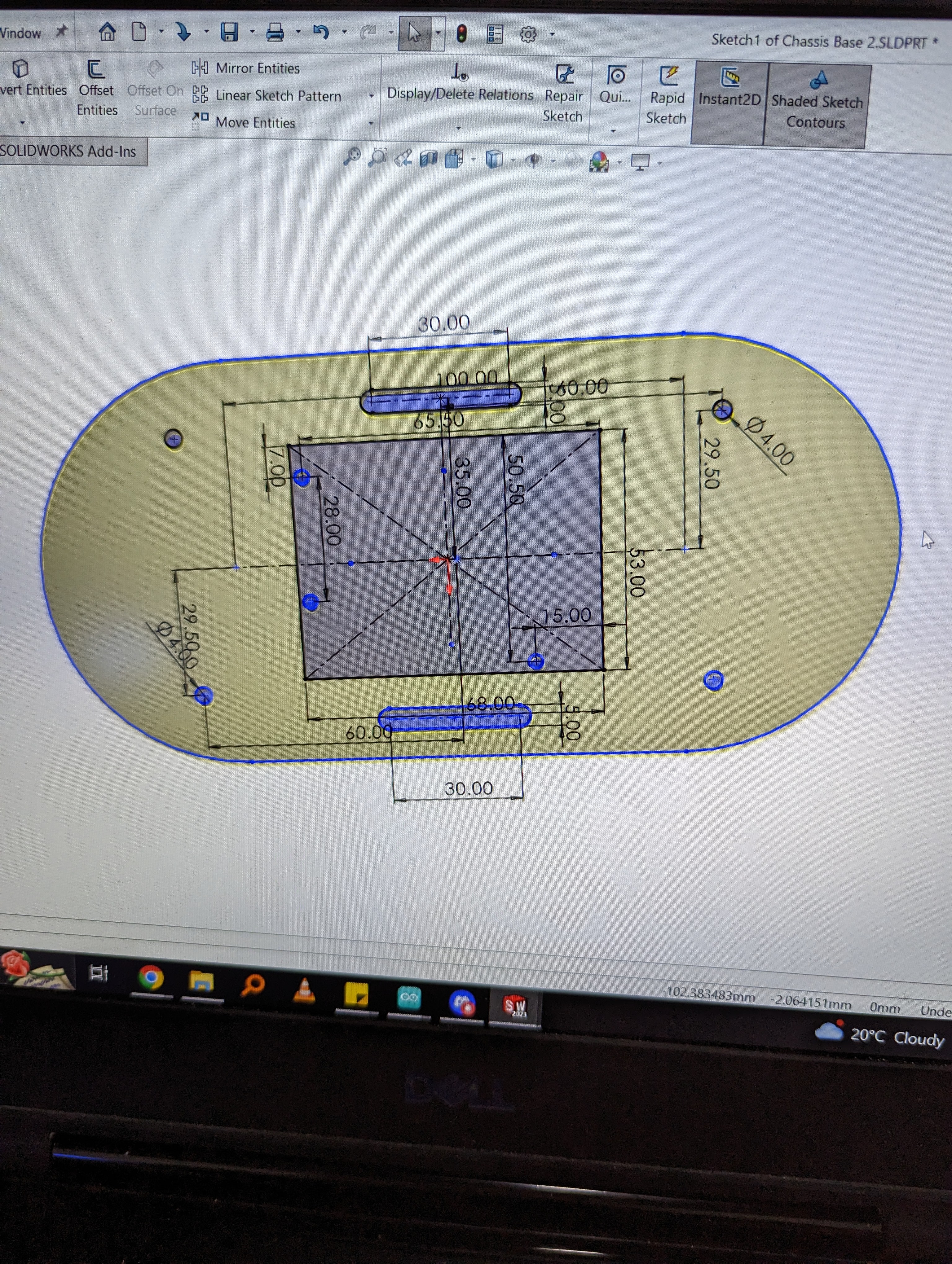
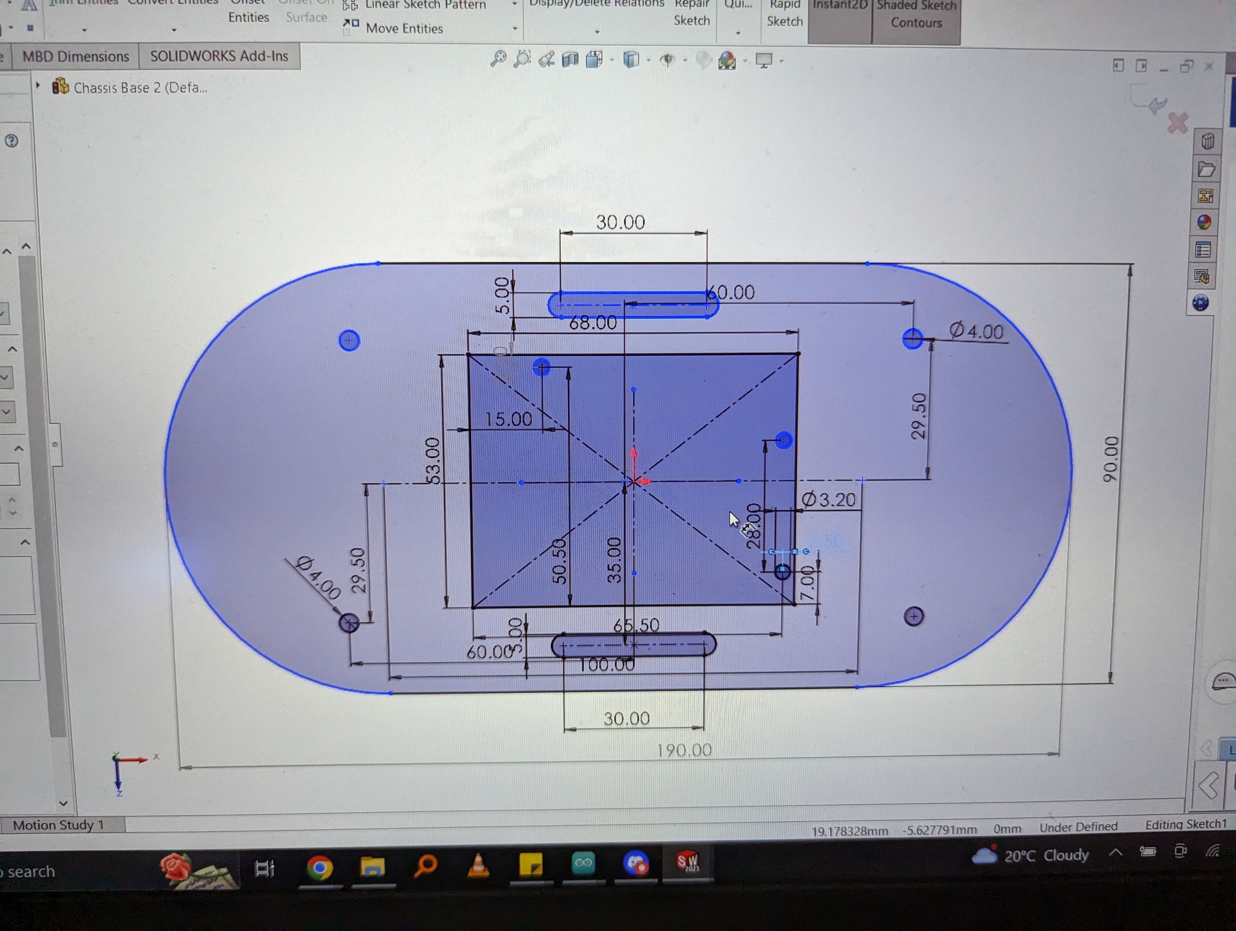
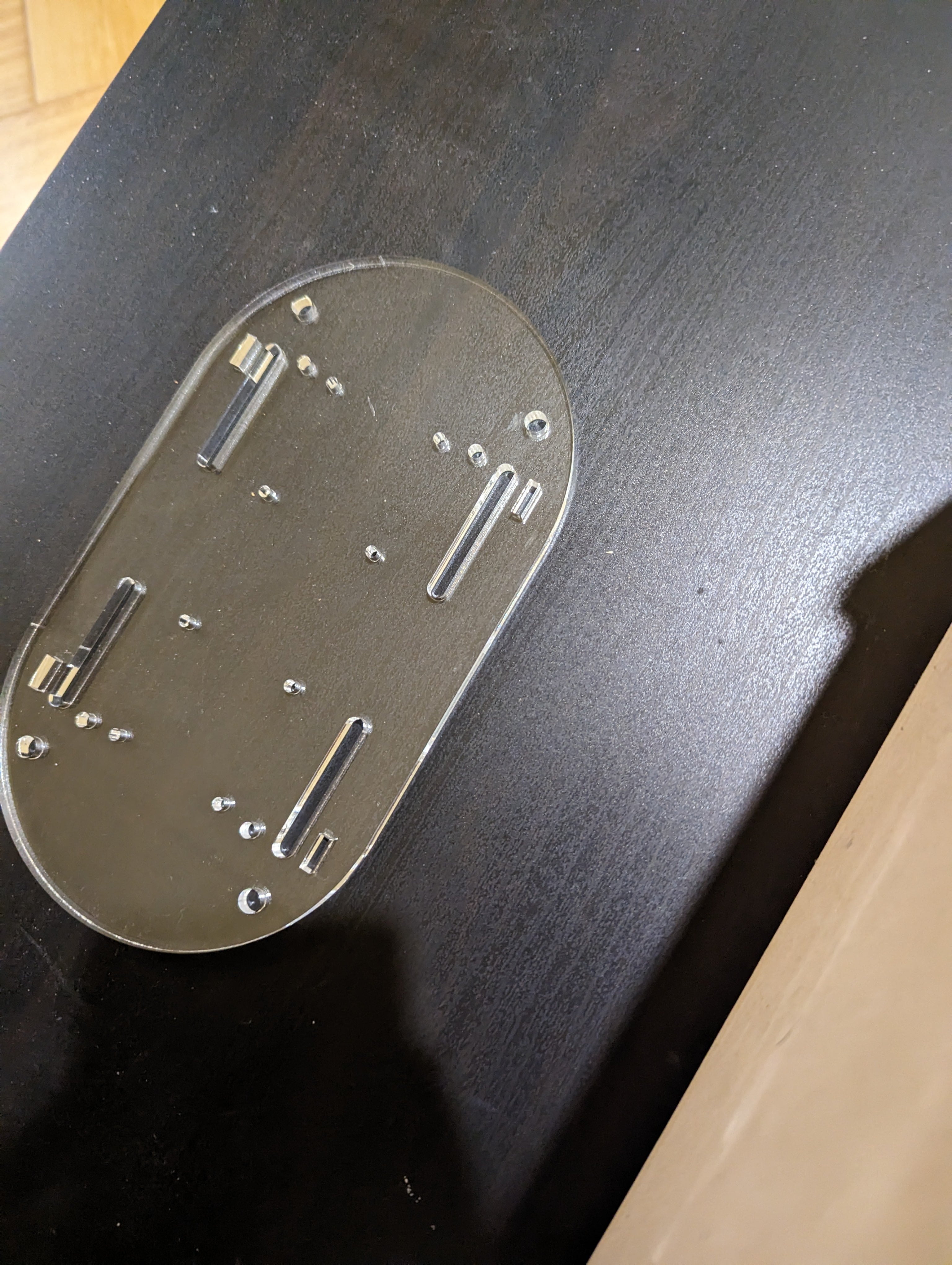
Of course as you can see, there were many iterations to my design, this was due to tolerance inaccuracies, poor mechanical fitting foresight, and a university degree consisting of theoretical knowledge and a sprinkling of practical knowledge that is only good to show off and hoping no one asks you more questions.
A × Brutal × Battlefield
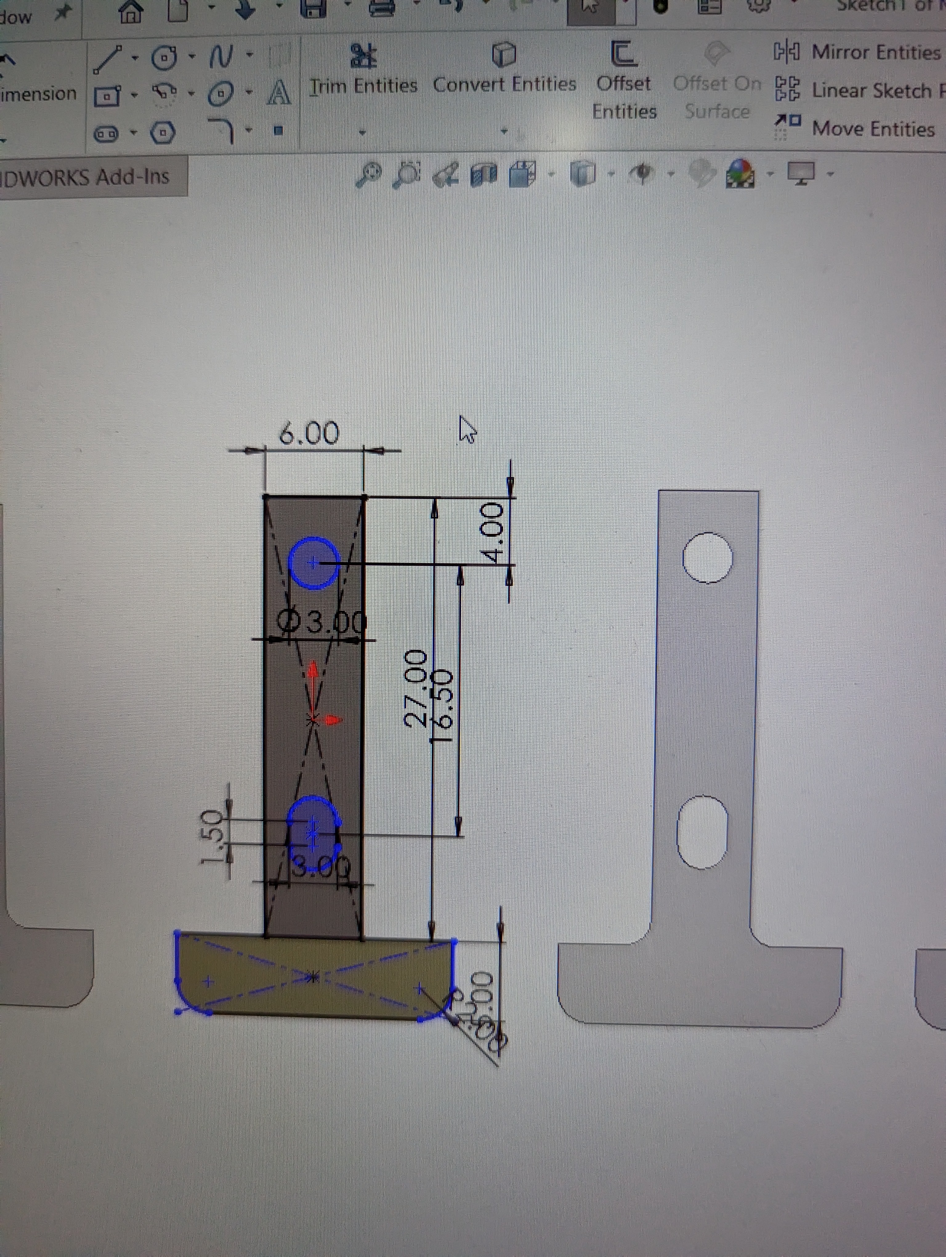
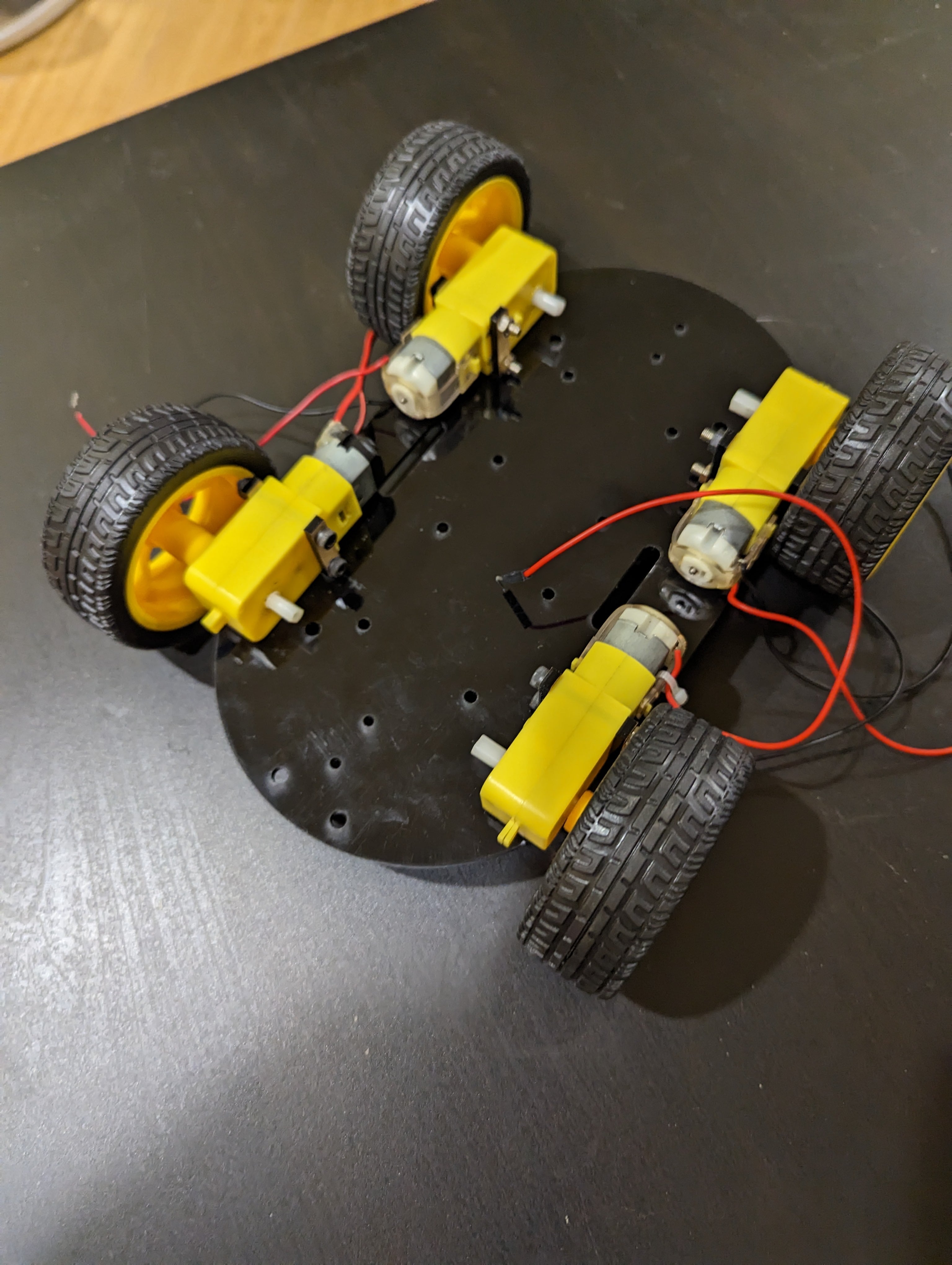
Okay so once I got a relatively working chassis design done that held the motors in place, I went back to the electronics. And.... it was a headache. So to begin with, here is an initial picture showing the motors being held in place via two laser cut pieces of acrylic with a recess at the bottom to locate the motor holes. Then two bolts are inserted into the motor holes and into the pieces of acrylic with a nut holding everything in place. This was very tedious to join due to the miniscule size of everything and hands that were not small anymore, I guess there was an advantage to being short and small in highschool. A picture of this setup can be seen below:
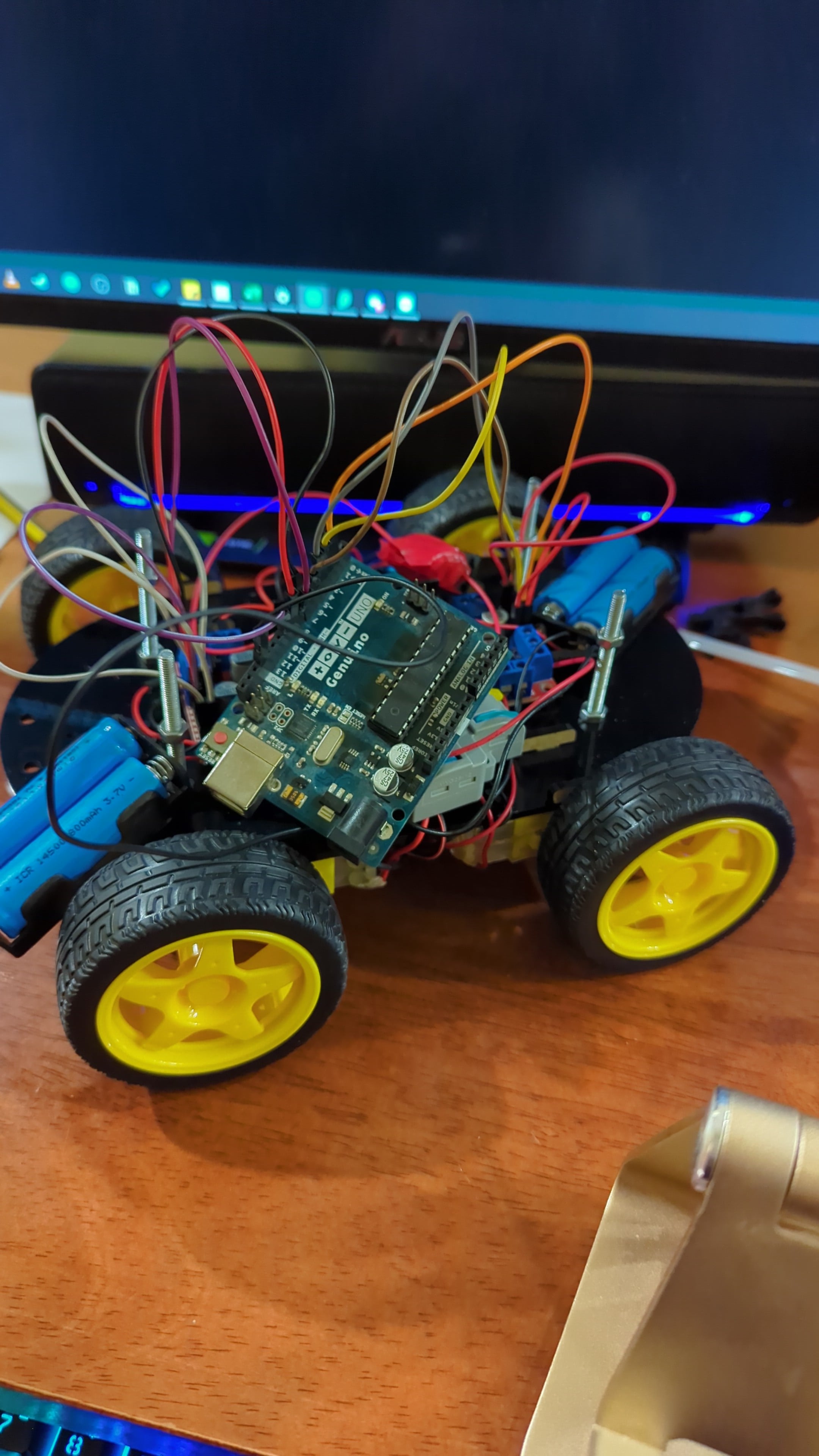
Afterwards, I moved on to focusing on the electronic connections to the microcontroller and H-Bridges. Now let me preface by saying I like symmetry, it is nice. Anyways moving on, since I wanted the robot to be a 4 wheel drive (or 4WD like the cool kids say), I used two H-Bridges as well as two 2x battery holder (for those with poor mental math, that’s 4 batteries in total). The idea was that I would place the two H-Bridges on opposing sides of the chassis board I designed, and the same with the batteries. Now you might ask why didn’t you just use a 4 battery holder, and to answer that please refer to the second sentence of this paragraph, of course it wasn’t negligence or poor design skills or anything, who would be so careless. Anywho, since everything was in testing phase, I didnt mount everything so I can quickly remove things, so as you can see below is a picture of the project starting to grow and having reached the second trimester and slowly maturing into a fully-fledged bab....I mean robot.
Once I started testing the electronics to see that everything was working, I started running into problems… many problems, and fixing one only made another problem appear. So an important part of documentation I feel is to talk about failures, in this case poor wire management, poor wire cutting skills, and probably running out of good luck after 6 weeks of it (don’t worry though it comes back later). A summary of issues I faced include, wires not properly connecting to connectors which leads to incomplete connections, wires not soldered properly leading to them disconnecting, in hindsight it really was just a poor wire connection issue. So with the help of Haitham-sama and lots of positive energy that started being drained by the second, we dismantled my entire bab…oh right robot and rewired EVERYTHING back again in a neat fashion. So once everything was wired up and ready to go, I started testing around with some sample code and my robot (I got it right this time), started moving along. Obviously not everything was connected just yet, the batteries were only powering the motors, and the microcontroller was only powered via cable through my laptop just to test everything.
Oh I also forgot to mention, thanks to Abdulghafour, I swapped out my arduino uno for a Mega 2560 Strong, which benefits from having voltage and ground pins corresopnding to every single signal pin, which there are 50 of! And since I designed this robot with upgradability in mind, this was a great option as I really would need a lot of pins. I mean seriously look at this beauty:
So with a newfound confidence, I decided to run some code, on the field without a wired connection. So I uploaded some code, wired the H-Bridge voltage output to the microcontroller and turned it on! Nope nope smoke once again… great. So I… fried the Mega 2560 Strong :/ due to a careless mistake. You see instead of connecting the microcontroller to the 5v output like a non-non-knowledgeable person would, I connected it to the 12v connections of the H-Bridge, which means it didn’t just get 12v as you might think, it got the full and I mean full power of 4 batteries revving their chemicals to the fullest which essentially fried the poor microcontroller. Newfound confidence gone in a flash of smoke, literally. I warned you that this section with electronics is a headache, which Haitham responded to that statement with a smile and a thumbs up.
So afterwards I ordered a new Mega 2560 Strong off of Aliexpress to replace the fried one like a good samaritan and another for me because it really is an absolutely cool piece of electronics. But those took like 3 weeks to arrive so I had to rely on another microcontroller, which was the arduino uno. Okay section over, that was too much text.
Resolve × And × Awakening
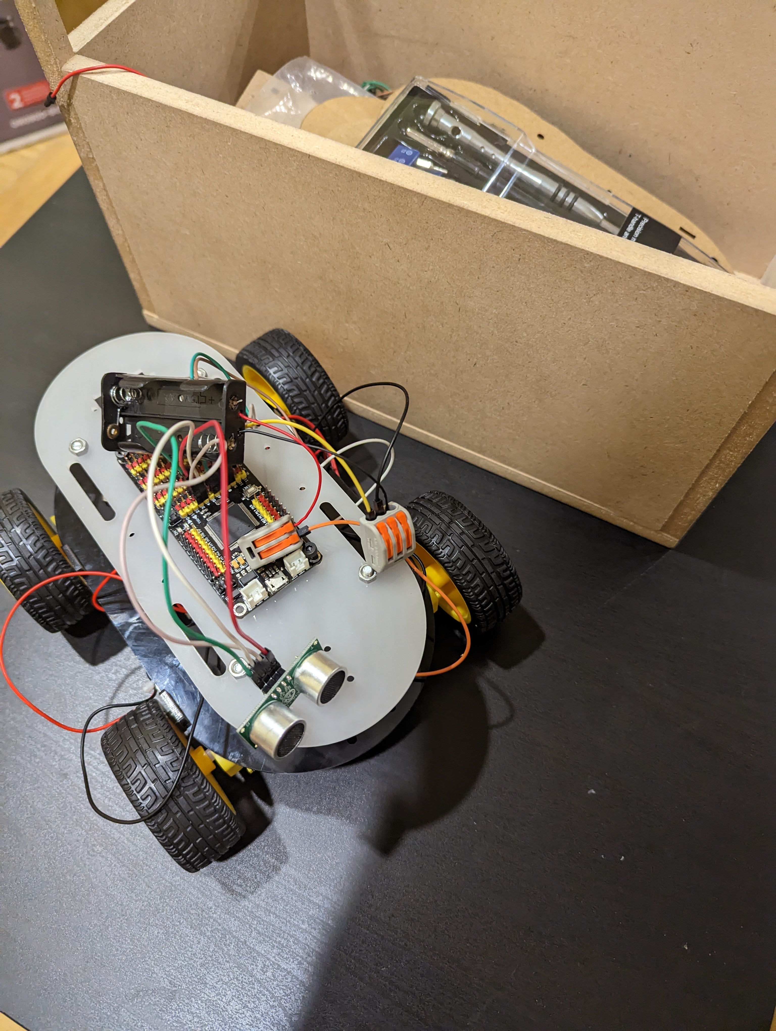
After being depressed for all of 30 minutes… I went back home. Only to come back the next day with a strong resolve and redesigned my chassis to accommodate the Arduino Uno. Not only that, I also made it such that there are holes for the Mega 2560 Strong (Ok that’s too long too many times, will be referred to as M2S henceforth). So this way the chassis is more modular and I can easily swap out the microcontrollers later on without wasting more material I mean even more material. Furthermore, I made four extra holes so that I can later on mount a PCB of my own design to manage all the wirings easily and neatly… in the future.
Now that I got the arduino mounted AND wired it to the correct voltage line, that being the 5v output of one of the H-Bridges, I fired up everything (figuratively) and it ran! The robot started moving, but without much brains to its motion. I was glad that it was just moving really even if it was dumb, like seeing a baby takes its first steps and then falling on the ground and then trying to shove an entire chair in its mouth you can totally eat a chair.
Inspiration × To × Evolve
So now that everything was wired up nicely and neatly, I just had to design the shell, the casing which will make it all look nice and tidy and professional(ish). So my first inspiration for the design was going to be a simple layer of wood frames that would make it look nice while still exposing the wiring. It was going to look like this, but 80% less cooler:

So on I went to test cut a few pieces of wood to ensure the validity of my design and with Haitham approving it and just about to hit the start button, Dr. Salman appeared all of a sudden, sensing a disturbance in the universe. He asked about my design idea and suggested something far less…material costly. And so that was the end of the wood frame idea really.
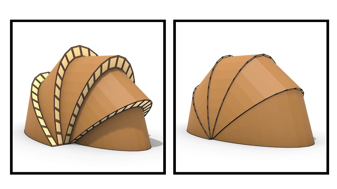
So for the next design idea, Dr. Salman suggested what I can only describe as a rotating paramteric shell made out of some paper that would be joined with a pin on two sides and placed over the robot. This would make it look like an actual beetle or Herbie (a volkswagon beetle), see the connection? Only problem with this was that the first prototype did not join properly as the different layers had to be incrementally smaller or I guess decrementally smaller that makes more sense. Kind of like this:
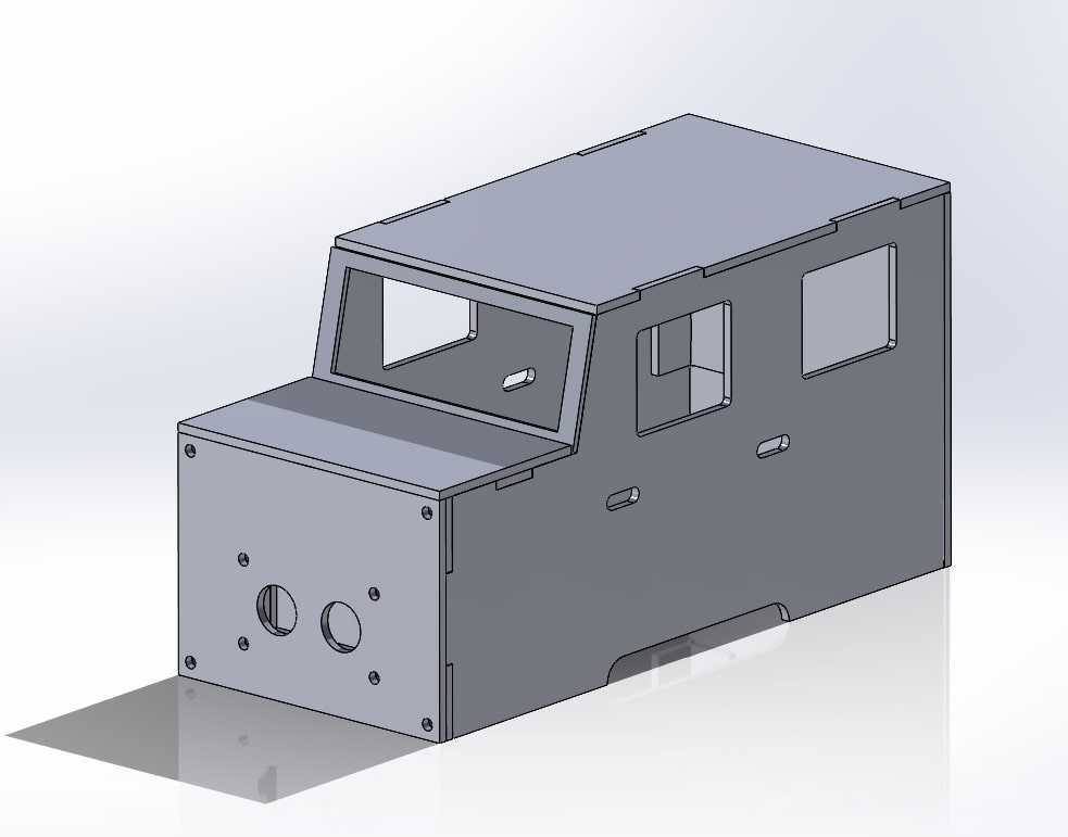
But I could not figure out how to measure the exact decrements they needed to be to make it all work. That was when I got a new idea from another student, Sakeena (Shoutout to her and Roaya’s beautifully crafted table lamp). The idea was to make a Mercedes G-Class casing for the robot which is an ingenious idea that will not only make my robot look cool it would be way easier to implement as that required pure CAD skills. CAD is basically the only thing I’m confident to say I am good at, and maybe programming (but like intermediate level). So off I went with designing the G-Class, and since it was going to be like a car, I added two holes for the ultrasonic sensor to pop out of the bumper with a mount designed to hold everything in place perfectly with a slot for the wiring to come out of. Below is a picture showing the design of the casing as well as a model for you to look at and be mesmirized by the 15 minute design I made:
(INSERT MODEL)
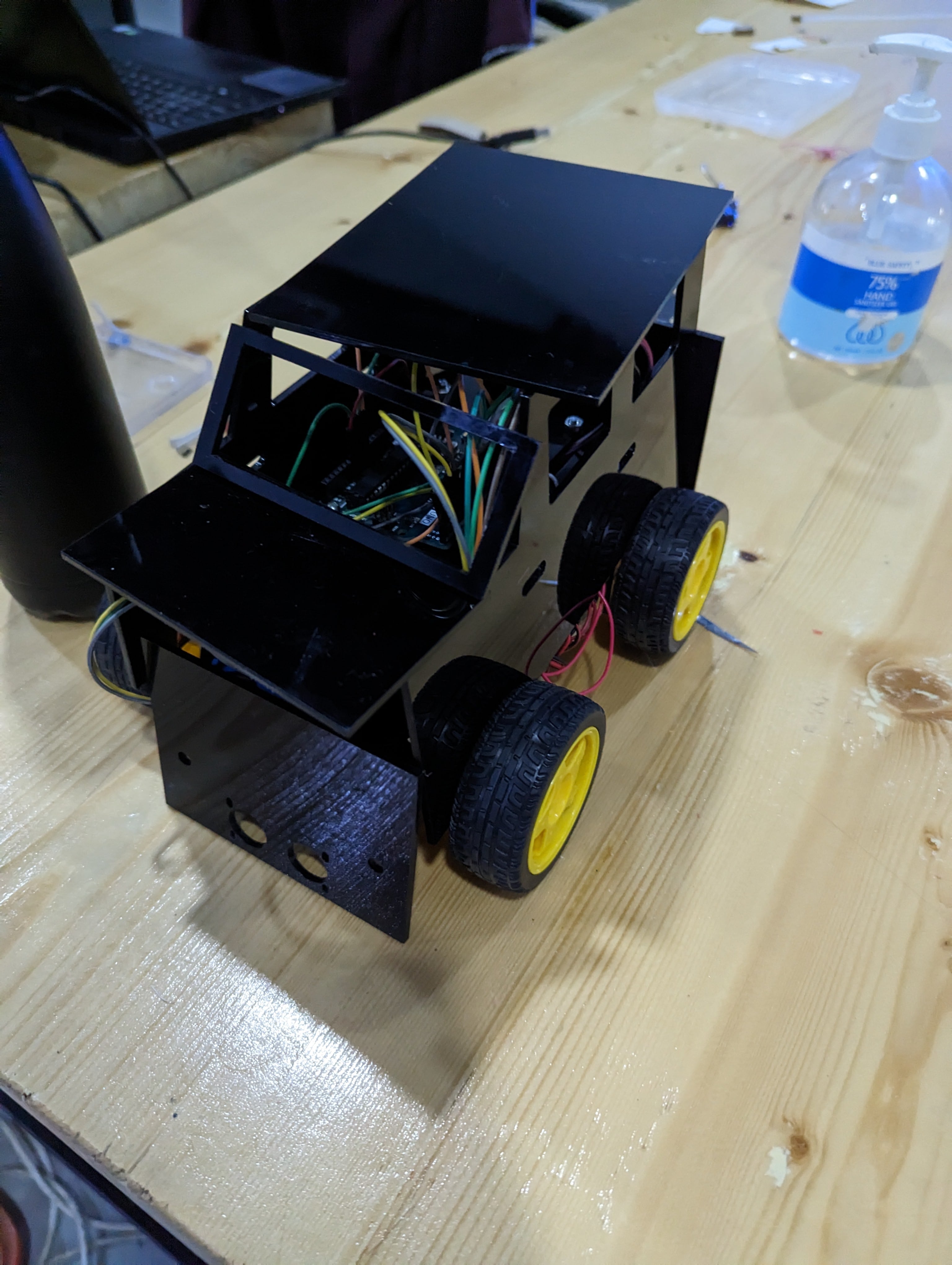
So the design was going to be made out of Acrylic a material I grew very fondly of to the dislike of Dr. Salman who I am sure is only sad at the amount of acrylic wasted on an amateur car design. But I swear it looks cool. So I cut up the acrylic and the goal was to glue everything together, and here is a picture showing how it would look like without anything being assembled just yet:
But then a wild Haitham appeared and commented on how I have to stick to the traditions and values of Fablab and FabAcademy and connect everything via joints rather than through glue like a ~~good engineer~~ the sloppy student that I am. Honestly glue and tape is the salvation of engineers, it is literally the glue to having everything work just fine until you touch it hard enough. So off I went redesigning everything all over again, well not really, just cut out some male and female holes for the joints to connect everything together… and voila the final design was complete.
Below is a picture of the complete wiring diagram for the whole setup:

Homecoming × And × Real Name
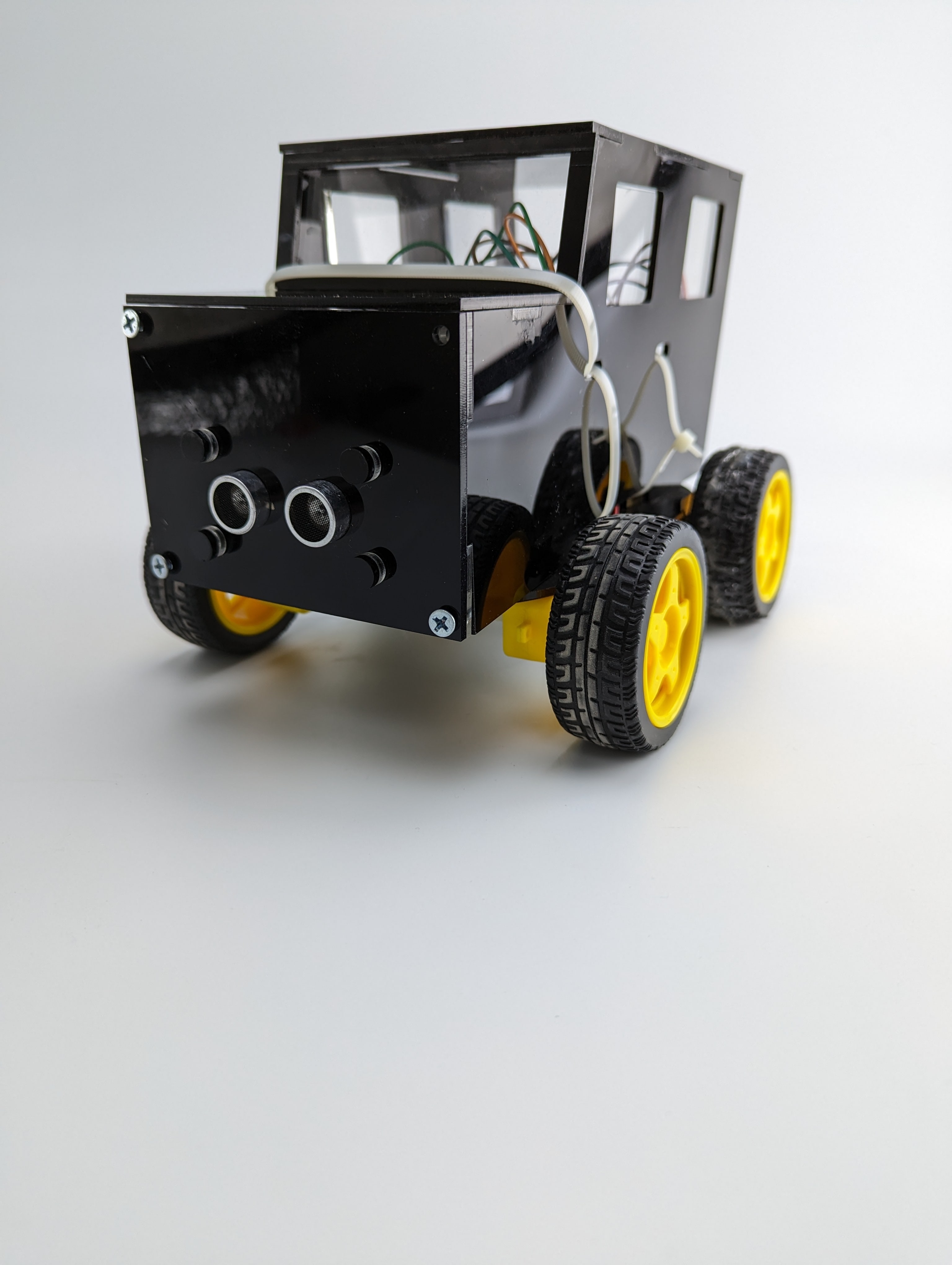
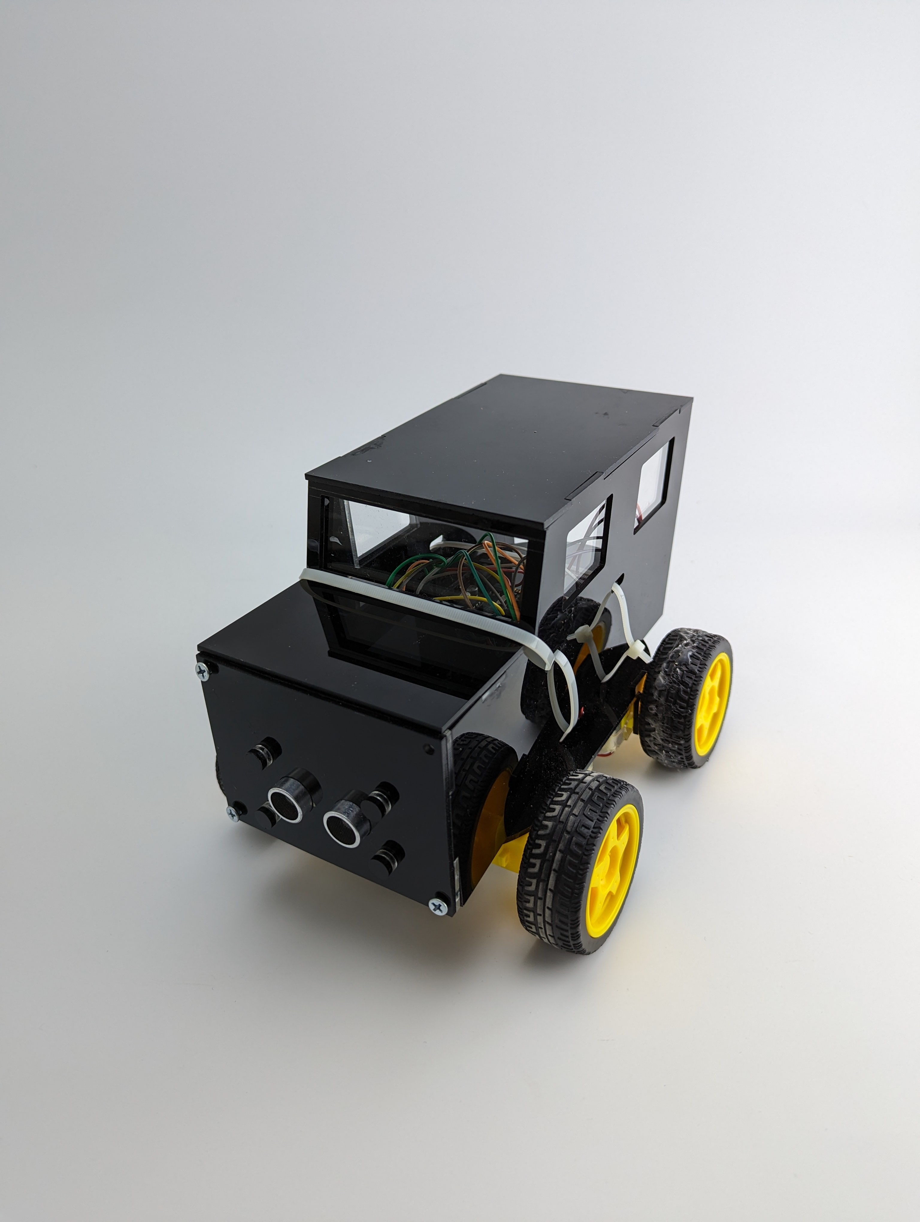
Featuring a slick black acrylic design, four ~~double glazed~~ cheap acrylic windows and a windshield, a trunk that allows for the arduino to be reprogrammed, and a bonnet with a switch to turn those 4WD ~~engines~~ motors on, is BB (so technically when I said baby before I was right) or Benz-Bot or Basel Bot.
Condition X And X Condition
So now that the mechatronic design is complete I moved on to the coding aspect of the robot, and while I know the code for my robot is quite primitive it is fully functional and allows the robot to completely navigate through an area while avoiding obstacles. So below is the code I wrote for the robot, fully commented for your convenience:
#include <NewPing.h>      // Include the Ultrasonic sensor library
#include <SPI.h>

// Front left motor pins
const int frontLeft_in1 = 11;
const int frontLeft_in2 = 2;
const int frontLeft_enA = A0;

// Front right motor pins
const int frontRight_in3 = 5;
const int frontRight_in4 = 6;
const int frontRight_enB = A1;

// Rear left motor pins
const int rearLeft_in1 = 7;
const int rearLeft_in2 = 8;
const int rearLeft_enA = A2;

// Rear right motor pins
const int rearRight_in3 = 13;
const int rearRight_in4 = 12;
const int rearRight_enB = A3;

// Ultrasonic sensor pins
#define TRIG_PIN 4 // Pin A0 on the Motor Drive Shield soldered to the ultrasonic sensor
#define ECHO_PIN 3 // Pin A1 on the Motor Drive Shield soldered to the ultrasonic sensor
#define MAX_DISTANCE 200 // sets maximum useable sensor measuring distance to 200cm
#define MAX_SPEED 150 // sets speed of DC traction motors to 150/250 or about 70% of full speed - to get power drain down.
#define MAX_SPEED_OFFSET 40 // this sets offset to allow for differences between the two DC traction motors
#define COLL_DIST 30 // sets distance at which robot stops and reverses to 30cm
#define TURN_DIST COLL_DIST + 20 // sets distance at which robot veers away from object

// Set up the NewPing library with the correct pins to measure distance.
NewPing sonar(TRIG_PIN, ECHO_PIN, MAX_DISTANCE);

int leftDistance, rightDistance; //distances on either side
int curDist = 0;
int speedSet = 0;

//-------------------------------------------- SETUP LOOP ----------------------------------------------------------------------------
void setup() {
  delay(1000); // delay for one second to allow time for the program to start
  Serial.begin(9600); // start the serial connection for debugging
 }
//------------------------------------------------------------------------------------------------------------------------------------

//---------------------------------------------MAIN LOOP ------------------------------------------------------------------------------
void loop() {
  curDist = readPing();   // read distance from the ultrasonic sensor
  if (curDist > COLL_DIST || curDist == 0){
    moveForward(); // if there are no obstacles in front, move forward
    delay(10); // wait for 10 milliseconds before repeating the loop
  }
  else{
    moveBackward(); // if there is an obstacle in front, move backward
    delay(100); // wait for 100 milliseconds before comparing the distance
    compareDistance(); // turn and compare distance to the left and right
  }
}

//-------------------------------------------------------------------------------------------------------------------------------------

void compareDistance() {
  moveStop(); // Stop the robot
  delay(1000); // Delay to allow the robot to stop completely
  turnLeft(); // Turn left and read the distance
  leftDistance = readPing();
  delay(1000); // Delay to allow the robot to turn completely
  turnRight(); // Turn right and read the distance
  turnRight();
  rightDistance = readPing();
  delay(1000); // Delay to allow the robot to turn completely
  turnLeft(); // Turn left to face forward
  if (leftDistance > rightDistance) { // If the left side is less obstructed
    turnLeft(); // Turn left
  }
  else if (rightDistance > leftDistance) { // If the right side is less obstructed
    turnRight(); // Turn right
  }
  else { // If both sides are equally obstructed
    turnRight(); // Turn right to avoid getting stuck
    turnRight();
  }
}

//-------------------------------------------------------------------------------------------------------------------------------------

/**
 * Stops the movement of the robot.
 */
function moveStop() {
  // Set the speed of both motors to 0 to stop movement.
  motorLeft.setSpeed(0);
  motorRight.setSpeed(0);

  // Stop both motors.
  motorLeft.stop();
  motorRight.stop();
}

//-------------------------------------------------------------------------------------------------------------------------------------

void moveForward() {
  for (speedSet = 0; speedSet < MAX_SPEED; speedSet += 2) // slowly bring the speed up to avoid loading down the batteries too quickly
  {
    analogWrite(rearLeft_enA, speedSet); // set rear left motor speed
    analogWrite(rearRight_enB, speedSet); // set rear right motor speed
    digitalWrite(rearLeft_in1, LOW); // set rear left motor direction
    digitalWrite(rearLeft_in2, HIGH); // set rear left motor direction
    digitalWrite(rearRight_in3, HIGH); // set rear right motor direction
    digitalWrite(rearRight_in4, LOW); // set rear right motor direction

    analogWrite(frontLeft_enA, speedSet); // set front left motor speed
    analogWrite(frontRight_enB, speedSet); // set front right motor speed
    digitalWrite(frontLeft_in1, HIGH); // set front left motor direction
    digitalWrite(frontLeft_in2, LOW); // set front left motor direction
    digitalWrite(frontRight_in3, LOW); // set front right motor direction
    digitalWrite(frontRight_in4, HIGH); // set front right motor direction

    curDist = readPing(); // read the current distance from the ultrasonic sensor
    if (curDist < COLL_DIST && curDist != 0){ // check if the distance is less than the collision distance and not zero
      moveStop(); // stop the robot
      break; // exit the for loop
    }
    delay(2); // wait for 2 milliseconds before checking the distance again
  }
}

//-------------------------------------------------------------------------------------------------------------------------------------

void moveBackward() {
  for (speedSet = 0; speedSet < MAX_SPEED; speedSet += 2) {  // slowly bring the speed up to avoid loading down the batteries too quickly
    // Set the motor speeds and directions
    analogWrite(rearLeft_enA, speedSet);
    analogWrite(rearRight_enB, speedSet);
    digitalWrite(rearLeft_in1, HIGH);
    digitalWrite(rearLeft_in2, LOW);
    digitalWrite(rearRight_in3, LOW);
    digitalWrite(rearRight_in4, HIGH);

    analogWrite(frontLeft_enA, speedSet);
    analogWrite(frontRight_enB, speedSet);
    digitalWrite(frontLeft_in1, LOW);
    digitalWrite(frontLeft_in2, HIGH);
    digitalWrite(frontRight_in3, HIGH);
    digitalWrite(frontRight_in4, LOW);

    delay(2); // delay to give motors time to spin up
  }
}

//-------------------------------------------------------------------------------------------------------------------------------------

void turnRight() {
  // Set left motors to go forward
  digitalWrite(rearLeft_in1, LOW);
  digitalWrite(rearLeft_in2, HIGH);

  // Set right motors to go backward
  digitalWrite(rearRight_in3, LOW);
  digitalWrite(rearRight_in4, HIGH);

  // Slowly bring up the speed to avoid loading down the batteries too quickly
  for (speedSet = 0; speedSet < MAX_SPEED; speedSet +=2)
  {
    analogWrite(frontRight_enB, speedSet+MAX_SPEED_OFFSET);
    analogWrite(frontLeft_enA, speedSet+MAX_SPEED_OFFSET);
    analogWrite(rearRight_enB, speedSet+MAX_SPEED_OFFSET);
    analogWrite(rearLeft_enA, speedSet+MAX_SPEED_OFFSET);
    delay(2);
  }

  // Run motors in this direction for a certain period of time
  delay(720);

  // Stop the robot
  moveStop();
}

//-------------------------------------------------------------------------------------------------------------------------------------

void turnLeft() {
  // Set left motors to go backward
  digitalWrite(rearLeft_in1, HIGH);
  digitalWrite(rearLeft_in2, LOW);

  // Set right motors to go forward
  digitalWrite(rearRight_in3, HIGH);
  digitalWrite(rearRight_in4, LOW);

  // Slowly bring up the speed to avoid loading down the batteries too quickly
  for (speedSet = 0; speedSet < MAX_SPEED; speedSet +=2)
  {
    analogWrite(frontRight_enB, speedSet+MAX_SPEED_OFFSET);
    analogWrite(frontLeft_enA, speedSet+MAX_SPEED_OFFSET);
    analogWrite(rearRight_enB, speedSet+MAX_SPEED_OFFSET);
    analogWrite(rearLeft_enA, speedSet+MAX_SPEED_OFFSET);
    delay(2);
  }

  // Run motors in this direction for a certain period of time
  delay(720);

  // Stop the robot
  moveStop();
}
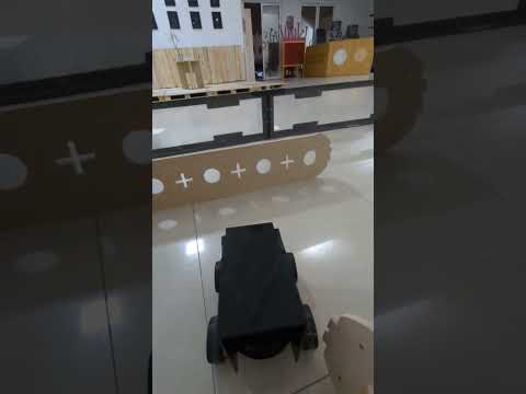
Last × Test Of × Resolve!
With the code ready to go and uploaded, it was finally time to test my robot. So I placed into an arena that we have setup with a maze for the robot to navigate through. Here is a video showing my BB with its quirky personality avoiding obstacles and going through the maze like a champ:
Past × And × Future
With the end of this project, I have learned many many many things and got to put a lot of what I learned in the past to the test and applied it in this robot. So here is a summary of some lessons learned when it comes to this project: -Always always always preferably use cardboard prototypes to test out first (preferably thick cardboard so it resembles hard material and doesnt give in through tolerance which wont be the case with your actual material) -When testing with actual material test with smaller cuts or portions of the design for fit, and then cut the whole thing. -Attempt to actually stick to deadlines and document as you go even if you suspect you have ADHD and think its a real issue blocking you from accomplishing a lot. -Always summon Haitham-sama or Duaa to verify electronics and wiring are correct before frying something. -Don’t try to overengineer something unless you test a lot and actually give yourself the time to do it. -Offer food to FabAcademy instructors to ~~bribe them~~ make them happy and in a good mood.
Besides those lessons learned, there are some improvements and future upgrades I have in mind for my robot: -I plan to make a wooden chassis with perfectly slotted holes. -Neatly wired design relying on a PCB to make everything clean and tidy. -Improved code for obstacle avoidance, over this primitive code ~~that was written in 20 mins~~. -Cleaner finish and design on the robot. -Multiple ultrasonic sensors for better navigation. -Rotating ultrasonic sensor for better path planning. -Possible Lidar integration over ultrasonic. -Rechargeable feature. -Perfectly slotted hole for reprogrammability. -Designed for ease of assembly and maintenance.
Request × And × Wish
Below you can click download the design files of the robot to make your own:
(INSERT DOWNLOAD LINK BUTTON THINGY)