7. Input & Output device
This week I learned about input and output devices, and I have worked on a small project.
Research
Input Interfacing allows sensors (Input Transducers) to communicate with PCs and Micro-controllers Interfacing is the method of connecting or linking together one device, especially a computer or micro-controller with another allowing us to design or adapt the output and input configurations of the two electronic devices so that they can work together. The simplest and most common type of input interfacing device is the push button switch. Mechanical ON-OFF toggle switches, push-button switches, rocker switches, key switches and reed switches, etc. are all popular as input devices because of their low cost and easy of input interfacing to any circuit. Also the operator can change the state of an input simply by operating a switch, pressing a button or moving a magnet over a reed switch.
Examples of input devices: Sensor, switch, botton, Variable Resistor
Examples of output devices: Buzzer, Motor, LCD screen
, LED Light
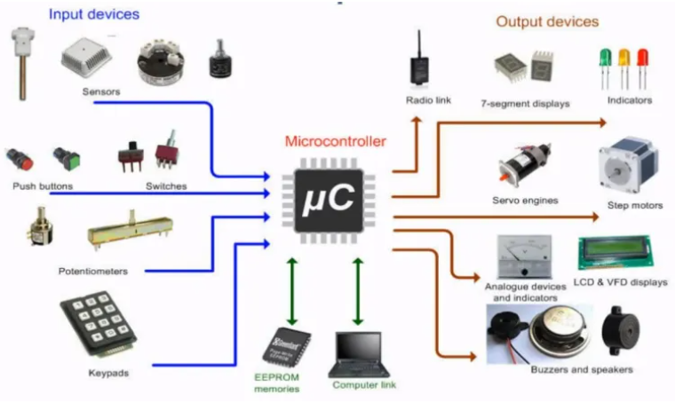
Output interface unit is also a type of interface unit which is used in computer system to convert digital signals into analog signals. It converts computational signals used by the computer system into the user signals.
Programming Process
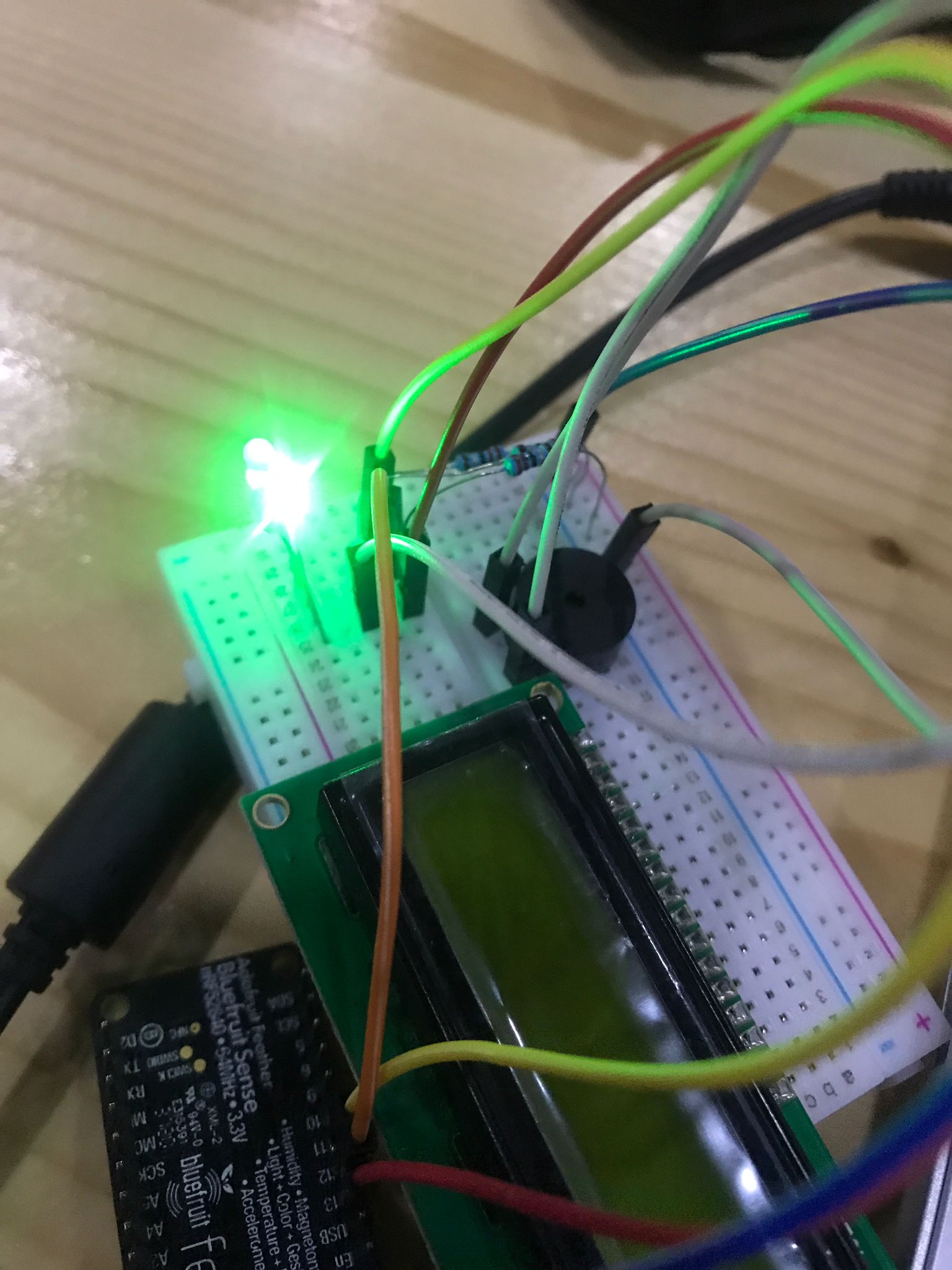
Make the connections: LEDg = 11; LEDr = 12; LEDb = 13; buzzer = 10; // Pin Defined RS = 5, EN = 6, D4 = 25, D5= 26, D6 = 24, D7 = 1;
I added an if statement in the code that turns the led and Buzzer on based on the temprature from the sensor is met.

Code
#include <Wire.h>
#include <SPI.h>
#include <Adafruit_BMP280.h>
#include <LiquidCrystal.h>
#include <LiquidCrystal_I2C.h>
Adafruit_BMP280 bmp; // use I2C interface
Adafruit_Sensor *bmp_temp = bmp.getTemperatureSensor();
Adafruit_Sensor *bmp_pressure = bmp.getPressureSensor();
const int LEDg = 11;
const int LEDr = 12;
const int LEDb = 13;
int buzzer = 10; // Pin Defined
const int RS = 5, EN = 6, D4 = 25, D5= 26, D6 = 24, D7 = 1;

LiquidCrystal lcd(RS, EN, D4, D5, D6, D7);
void setup() {
  pinMode ( buzzer, OUTPUT);  // Buzzer set as OUTPUT
  lcd.begin(16, 2);
  pinMode (LEDg, OUTPUT);
  pinMode (LEDr, OUTPUT);
  pinMode (LEDb, OUTPUT);

  Serial.begin(9600);
  while ( !Serial ) delay(100);   // wait for native usb
  Serial.println(F("BMP280 Sensor event test"));

  unsigned status;
  //status = bmp.begin(BMP280_ADDRESS_ALT, BMP280_CHIPID);
  status = bmp.begin();
  if (!status) {
    Serial.println(F("Could not find a valid BMP280 sensor, check wiring or "
                     "try a different address!"));
    Serial.print("SensorID was: 0x"); Serial.println(bmp.sensorID(), 16);
    Serial.print("        ID of 0xFF probably means a bad address, a BMP 180 or BMP 085\n");
    Serial.print("   ID of 0x56-0x58 represents a BMP 280,\n");
    Serial.print("        ID of 0x60 represents a BME 280.\n");
    Serial.print("        ID of 0x61 represents a BME 680.\n");
    while (1) delay(10);
  }

  /* Default settings from datasheet. */
  bmp.setSampling(Adafruit_BMP280::MODE_NORMAL,     /* Operating Mode. */
                  Adafruit_BMP280::SAMPLING_X2,     /* Temp. oversampling */
                  Adafruit_BMP280::SAMPLING_X16,    /* Pressure oversampling */
                  Adafruit_BMP280::FILTER_X16,      /* Filtering. */
                  Adafruit_BMP280::STANDBY_MS_500); /* Standby time. */

  bmp_temp->printSensorDetails();
}

void loop() {

  int pushed = digitalRead(10);
  sensors_event_t temp_event, pressure_event;
  bmp_temp->getEvent(&temp_event);
  bmp_pressure->getEvent(&pressure_event);

  Serial.print(F("Temperature = "));
  Serial.print(temp_event.temperature + 10);
  Serial.println(" *C");

  Serial.print(F("Pressure = "));
  Serial.print(pressure_event.pressure);
  Serial.println(" hPa");

  Serial.println();
  delay(100);

  if (temp_event.temperature + 10 < 33) {
    digitalWrite(13, LOW);
    digitalWrite(12, HIGH);
    digitalWrite(11, LOW);
    noTone(buzzer);
    lcd.setCursor(0, 0);         // move cursor to   (0, 0)
    lcd.print("LOW TEMPRATURE");
    lcd.setCursor(0, 1);         // move cursor to   (0, 0)
    lcd.print(temp_event.temperature + 10);
    delay(1000);

  }
  else if (temp_event.temperature + 10 > 39) {
    digitalWrite(13, HIGH);
    digitalWrite(12, LOW);
    digitalWrite(11, LOW);
    tone(buzzer, 100, 1000); // (pin, frequency, duration time)
    lcd.setCursor(0, 0);         // move cursor to   (0, 0)
    lcd.print("HIGH Temprature");
    lcd.setCursor(0, 1);         // move cursor to   (0, 0)
    lcd.print(temp_event.temperature + 10);
    delay(1000);

  }


  else if (temp_event.temperature + 10 < 39 && temp_event.temperature + 10 > 33)
  { digitalWrite(13, LOW);
    digitalWrite(12, LOW);
    digitalWrite(11, HIGH);
    lcd.clear();
    noTone(buzzer);
    lcd.setCursor(0, 0);         // move cursor to   (0, 0)
    lcd.print("Moderate Temprature");
    lcd.setCursor(0, 1);         // move cursor to   (0, 0)
    lcd.print(temp_event.temperature + 10);
    delay(1000);

  }
}
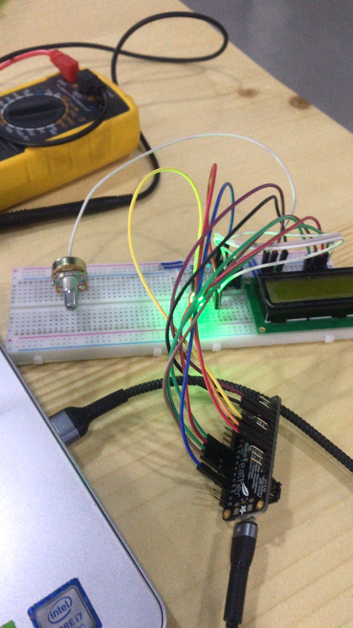
problems
LCD was not working because of the wrong connection So I figured out the connection and corrected it, and I had to connect the 2 power pins on the LCD together to activate the backlight