4. Embedded programming
This week I worked on programming with microcontroller using arduino IDE.
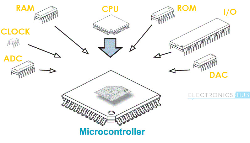
What is Microcontroller?
“A microcontroller is a compact integrated circuit designed to govern a specific operation in an embedded system. A typical microcontroller includes a processor, memory and input/output (I/O) peripherals on a single chip.”
Advantages of Microcontrollers:
-
A Microcontroller is a true device that fits the computer-on-a-chip idea.
-
No need for any external interfacing of basic components like Memory, I/O Ports, etc.
-
Microcontrollers doesn’t require complex operating systems as all the instructions must be written and stored in the memory. (RTOS is an exception).
Disadvantages of Microcontrollers:
-
Microcontrollers are not known for their computation power.
-
The amount of memory limits the instructions that a microcontroller can execute.
-
No Operating System and hence, all the instruction must be written.
Applications of Microcontrollers:
-
Front Panel Controls in devices like Oven, washing Machine etc.
-
Function Generators.
-
Smoke and Fire Alarms.
-
Home Automation Systems.
-
Automatic Headlamp ON in Cars.
-
Speed Sensed Door Locking System.
Arduino
“Arduino is an open-source platform used for building electronics projects. Arduino consists of both a physical programmable circuit board (often referred to as a microcontroller) and a piece of software, or IDE (Integrated Development Environment) that runs on your computer, used to write and upload computer code to the physical board.”
Arduino MKR WiFi 1010 : The MKR WiFi 1010 is a dual processor device that invites for experimentation. Hacking the WiFiNINA module allows you to.
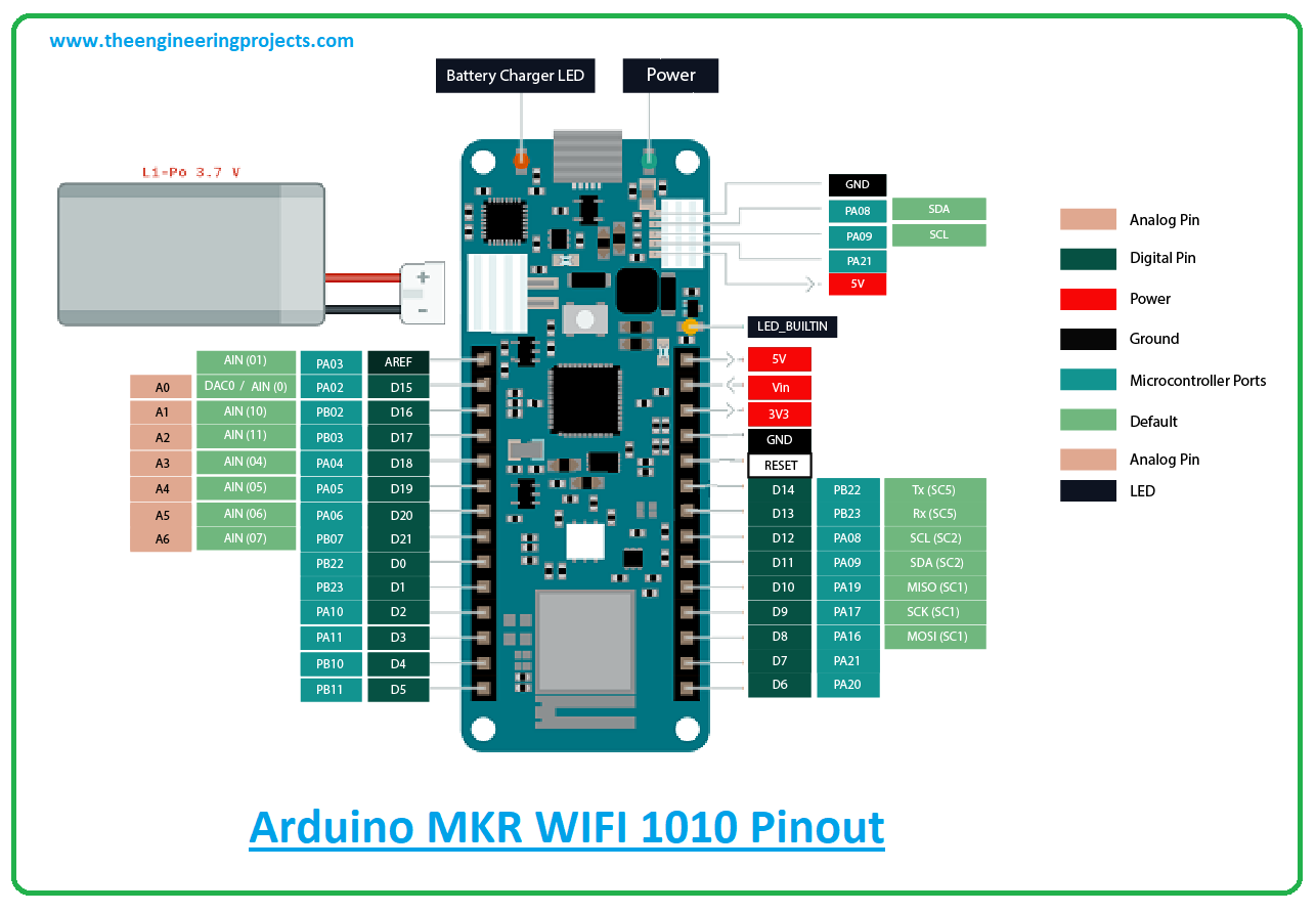
Any beginner, maker, or expert looking to get started with the Internet of Things should choose the MKR WiFi 1010. (IoT). It includes the well-known 32-bit Arm® Cortex®-M0 SAMD21 CPU as well as the ECC508 crypto-chip for security. The board is a member of the MKR family, where you may pick from a wide range of shields to quickly and easily construct projects!
Application:
- 1- Bluetooth
- 2- WiFi
- 3- IoT
The Arduino MKR Wifi datasheet taught me a lot about the board’s pins, which will be very helpful while accomplishing my objectives. I learned about the pins’ uses, such as which pins are analog and which pins are digital. Digital pins can be connected to digital inputs and outputs, and analog pins can be connected to analog sensors. It will be very helpful for input and output assignments to have this information about pins. Additionally, the Arduino MKR WiFi 1010 is NOT 5V tolerant and only supports 3.3V I/Os. The battery charger for the Arduino MKR WiFi 1010 has a minimum charging current of 512 mA. Please make sure the battery you’ll be using can be charged with this charger.
##Tasks
- First, download the Arduino app from the company’s official website.
- The board had to be downloaded to the Arduino IDE.
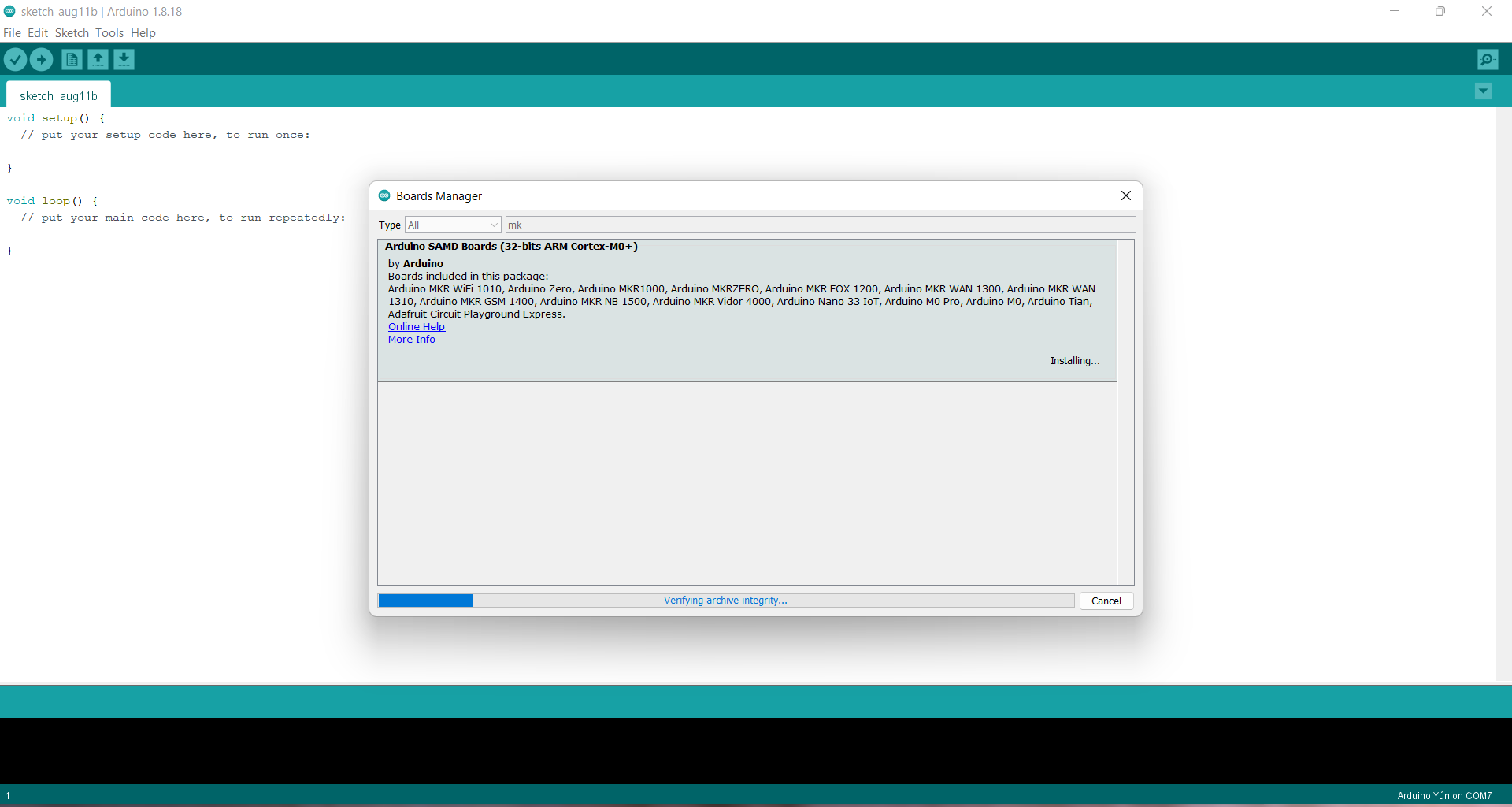
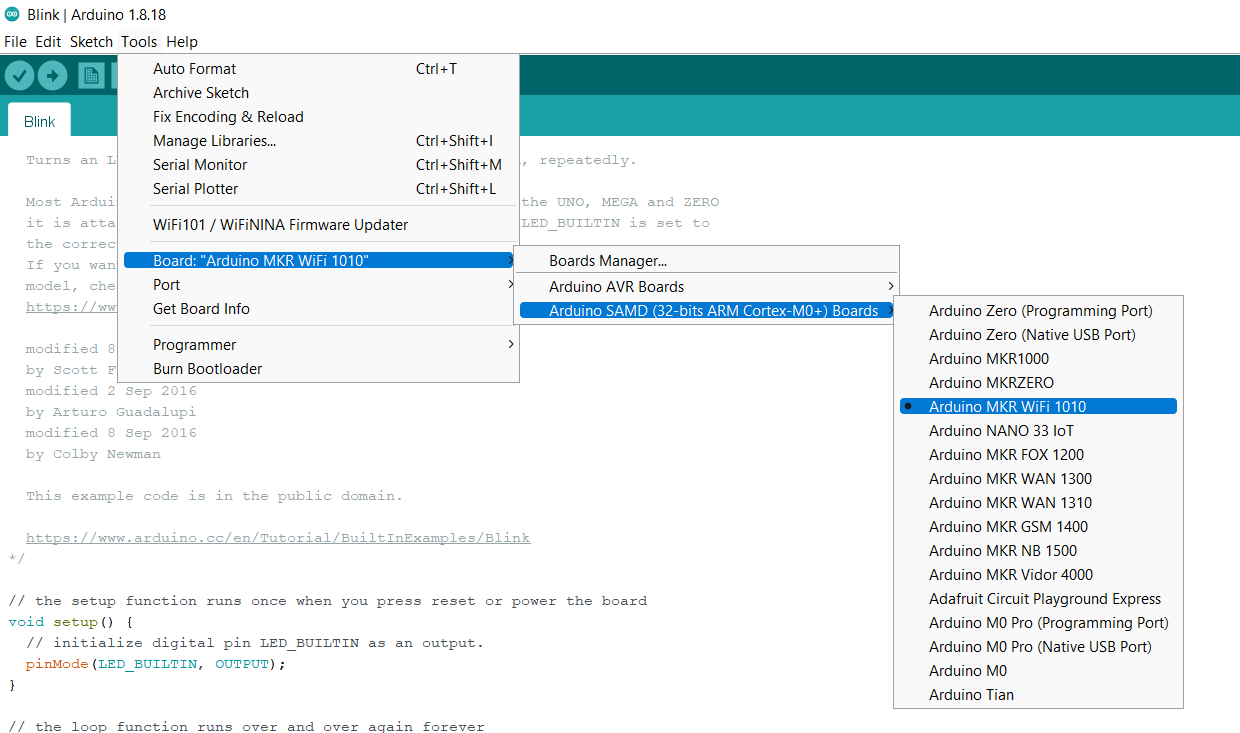
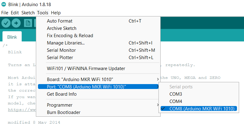
- before starting, choose the right board and port.
Task1
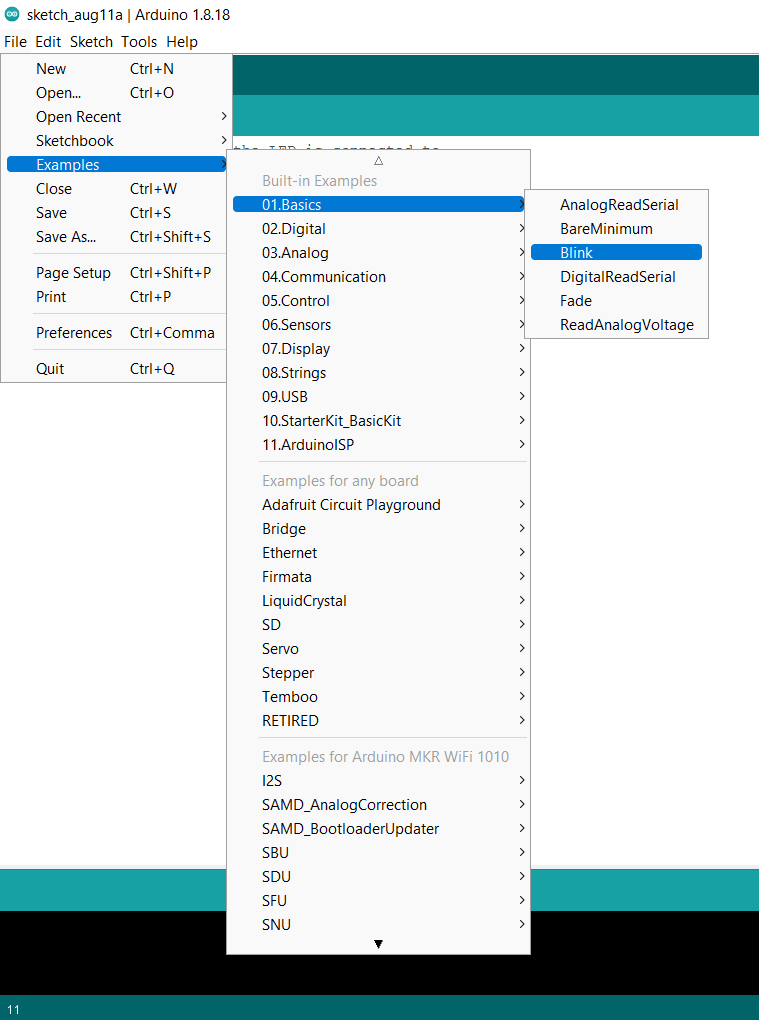
- I began by using Blink Example, which causes the programmable LED light to alternately turn on and off for one second.
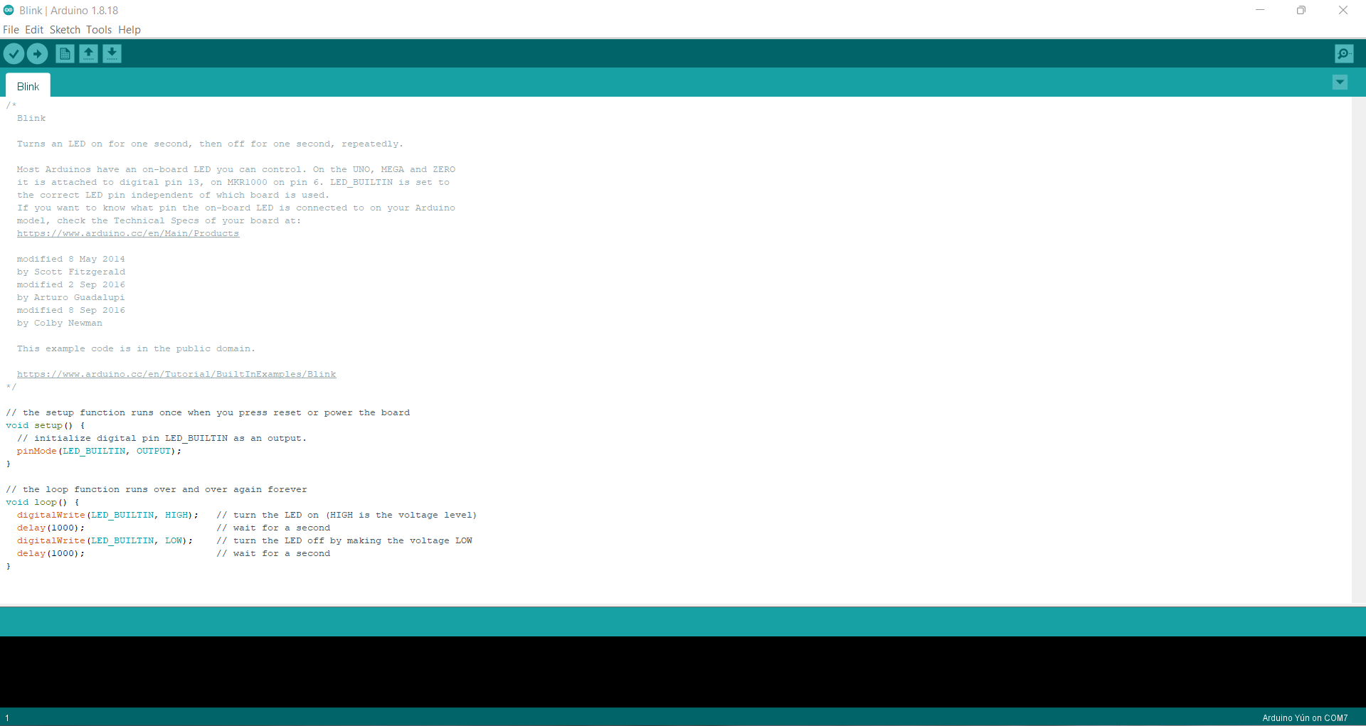
- The code
void setup() {
  // initialize digital pin LED_BUILTIN as an output.
  pinMode(LED_BUILTIN, OUTPUT);
}

// the loop function runs over and over again forever
void loop() {
  digitalWrite(LED_BUILTIN, HIGH);   // turn the LED on (HIGH is the voltage level)
  delay(1000);                       // wait for a second
  digitalWrite(LED_BUILTIN, LOW);    // turn the LED off by making the voltage LOW
  delay(1000);                       // wait for a second
}
Final result
Task2
- I then tried using the function random to set the light to come on for an arbitrary period of time.
*/
void setup() {
  // initialize digital pin LED_BUILTIN as an output.
  pinMode(LED_BUILTIN, OUTPUT);
}

// the loop function runs over and over again forever
void loop() {
int A=random(500,5000);
Serial.println(A);
int B=random(500,5000);

for(int j=0; j<10; j++){
  digitalWrite(LED_BUILTIN,HIGH);
  delay(A);
   digitalWrite(LED_BUILTIN,LOW);
  delay(B);
}
}
Final result
Task3
- the last thing, I used morse code to make the light on and off with my name “Hana” using this website
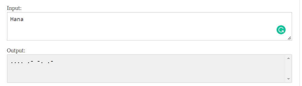
“I used 0.5 second light on for dot, 1.5 second light on for dash, 0.5 second light off for space between letters, and 2.5 light off for the end of the word.”
// the setup function runs once when you press reset or power the board
void setup() {
  // initialize digital pin LED_BUILTIN as an output.
  pinMode(LED_BUILTIN, OUTPUT);
}

// the loop function runs over and over again forever
void loop() {

  //H
  digitalWrite(LED_BUILTIN, HIGH);   // turn the LED on (HIGH is the voltage level)
  delay(500);                       // wait for a second
  digitalWrite(LED_BUILTIN, LOW);    // turn the LED off by making the voltage LOW
  delay(500);                       // wait for a second

    digitalWrite(LED_BUILTIN, HIGH);   // turn the LED on (HIGH is the voltage level)
  delay(500);                       // wait for a second
  digitalWrite(LED_BUILTIN, LOW);    // turn the LED off by making the voltage LOW
  delay(500);                       // wait for a second

    digitalWrite(LED_BUILTIN, HIGH);   // turn the LED on (HIGH is the voltage level)
  delay(500);                       // wait for a second
  digitalWrite(LED_BUILTIN, LOW);    // turn the LED off by making the voltage LOW
  delay(500);                       // wait for a second

    digitalWrite(LED_BUILTIN, HIGH);   // turn the LED on (HIGH is the voltage level)
  delay(500);                       // wait for a second
  digitalWrite(LED_BUILTIN, LOW);    // turn the LED off by making the voltage LOW
  delay(500);                       // wait for a second

  //end ltr
  digitalWrite(LED_BUILTIN, LOW);    // turn the LED off by making the voltage LOW
  delay(500);                       // wait for a second
//a
      digitalWrite(LED_BUILTIN, HIGH);   // turn the LED on (HIGH is the voltage level)
  delay(500);                       // wait for a second
  digitalWrite(LED_BUILTIN, LOW);    // turn the LED off by making the voltage LOW
  delay(500);                       // wait for a second

      digitalWrite(LED_BUILTIN, HIGH);   // turn the LED on (HIGH is the voltage level)
  delay(1500);                       // wait for a second
  digitalWrite(LED_BUILTIN, LOW);    // turn the LED off by making the voltage LOW
  delay(500);                       // wait for a second

//end lt
  digitalWrite(LED_BUILTIN, LOW);    // turn the LED off by making the voltage LOW
  delay(500);                       // wait for a second
//n
        digitalWrite(LED_BUILTIN, HIGH);   // turn the LED on (HIGH is the voltage level)
  delay(1500);                       // wait for a second
  digitalWrite(LED_BUILTIN, LOW);    // turn the LED off by making the voltage LOW
  delay(500);                       // wait for a second

 digitalWrite(LED_BUILTIN, HIGH);   // turn the LED on (HIGH is the voltage level)
  delay(500);                       // wait for a second
  digitalWrite(LED_BUILTIN, LOW);    // turn the LED off by making the voltage LOW
delay(500);                       // wait for a second
//end ltr
  digitalWrite(LED_BUILTIN, LOW);    // turn the LED off by making the voltage LOW
  delay(500);                       // wait for a second

//a
        digitalWrite(LED_BUILTIN, HIGH);   // turn the LED on (HIGH is the voltage level)
  delay(500);                       // wait for a second
  digitalWrite(LED_BUILTIN, LOW);    // turn the LED off by making the voltage LOW
  delay(500);                       // wait for a second

   digitalWrite(LED_BUILTIN, HIGH);   // turn the LED on (HIGH is the voltage level)
  delay(1500);                       // wait for a second
  digitalWrite(LED_BUILTIN, LOW);    // turn the LED off by making the voltage LOW
  delay(500);                       // wait for a second

//end word
  digitalWrite(LED_BUILTIN, LOW);    // turn the LED off by making the voltage LOW
  delay(2500);
}
Final result
Task4
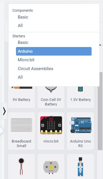
This task entails trying out a different TinkerCAD programming environment. A similar programming environment to Arduino and python is TinkerCAD. Tinkercad Circuits is the easiest way to get your students started with learning electronics. Using our interactive circuit editor, students can explore, connect, and code virtual projects with a bottomless toolbox of simulated components.
- 1- The first step is to open the TinkerCad circuit and then go to new / circuit to start building new code.

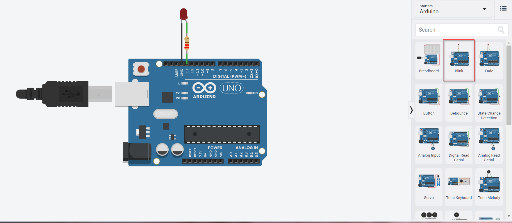
- 2-choose Arduino from basic component
- 3- It will open a lot of examples of circuits, I had chosen the same example I did before, the Blink example.
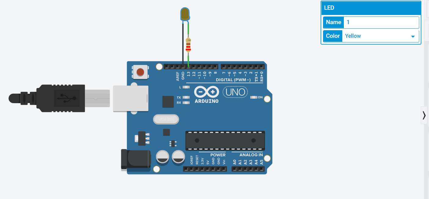
- 4- I can change the name and color of the LED so I choose my favorite color blue.
- 5- Go to code then choose from blocks to start doing the code.
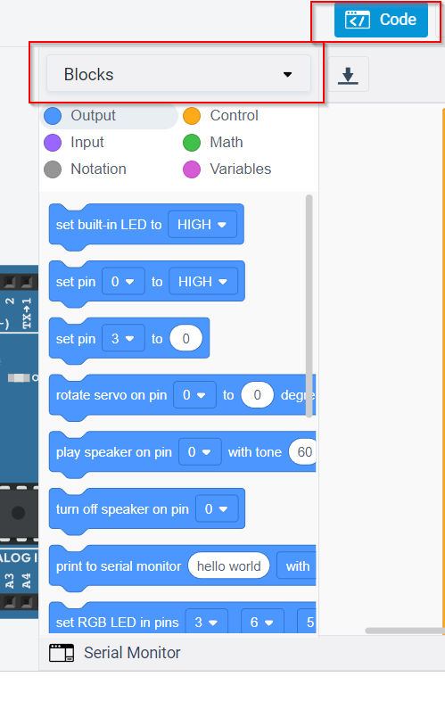
- 6-use output and control to build a code gor blinking.
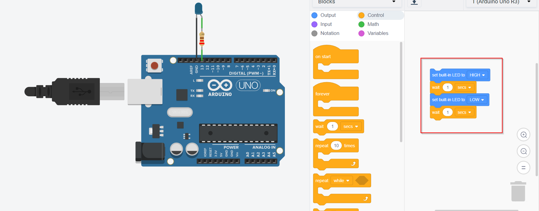
- 7- press on start simulation to see the result.
Final result
- I also try doing morse code that I did it with Arduino IDE.
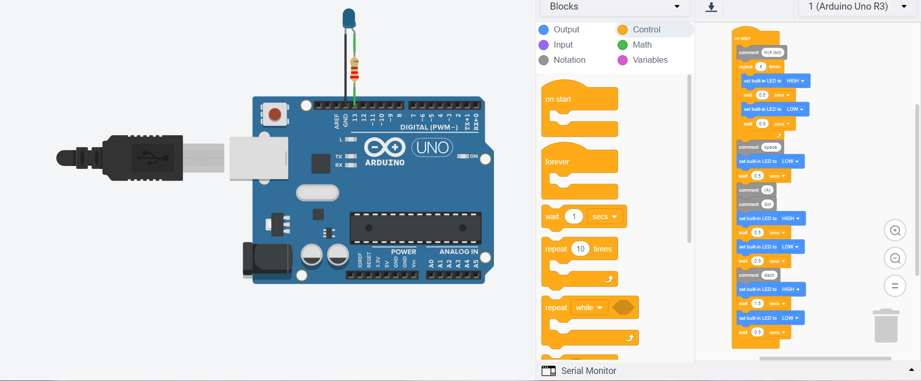
Final result
My feedback
Although I had previously programmed, this was my first time using the Arduino language. With the help of the examples and resources on their own website, it was a straightforward and simple experience. It was simple, efficient, and helpful to translate the name into Morse code; we may use it to communicate information over large distances, for example.