7. Input & Output device
What is signal ?
“An electromagnetic or electrical current used to transfer data from one system or network to another is known as a signal. A signal is a process that transmits knowledge about a phenomenon.”
Analog signal
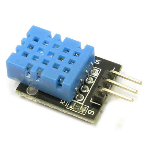
“Any continuous signal that has a time-varying feature (variable) that represents another time-varying quantity, or is comparable to another time-varying signal, is said to be an analog signal. Small but significant oscillations in the waveform distinguish it from a digital signal. The sensor I used is DHT 11 and it is Analog signal.”
Digital signal
“A digital signal employs discrete (discontinuous) values. In contrast, a continuous range of values is used to represent information in non-digital (or analog) systems. Despite the fact that digital representations are discrete, the information they convey can be continuous or discrete, such as sounds, images, or other measures of continuous systems.”

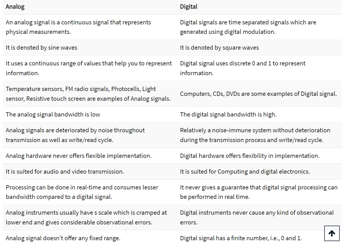
Difference Between Analog and Digital Signal
Task1
- After all things I did, Now I tried to connect the sensor with the microcontroller using Arduino. I used temperature and humidity sensors DHT 11.
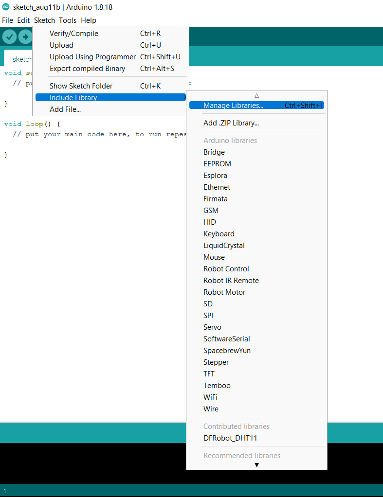
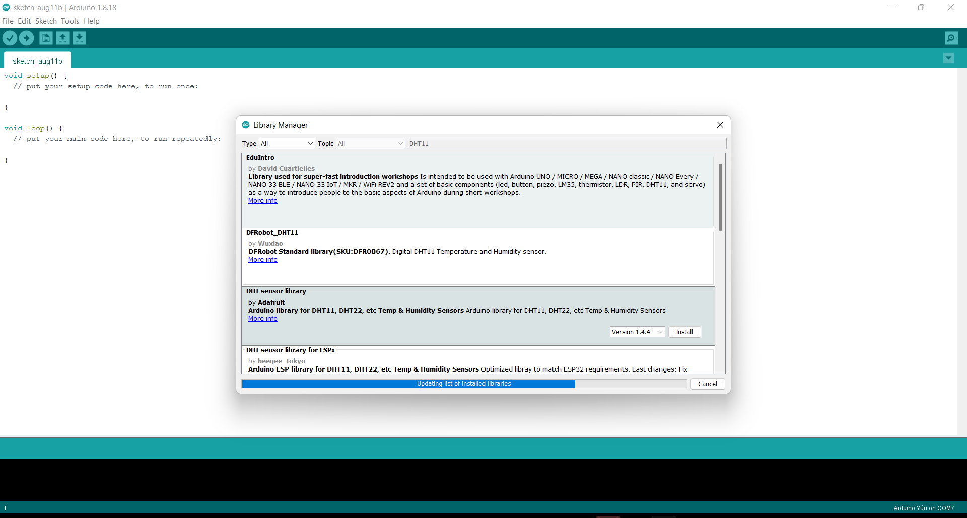
- First I have to download the library of the Arduino.
- This is the code I used for DHT 11 sensor.
#include <DFRobot_DHT11.h>
DFRobot_DHT11 DHT;
#define DHT11_PIN 10

void setup(){
  Serial.begin(115200);
}

void loop(){
  DHT.read(DHT11_PIN);
  Serial.print("temp:");
  Serial.print(DHT.temperature);
  Serial.print("  humi:");
  Serial.println(DHT.humidity);
  delay(1000);
}
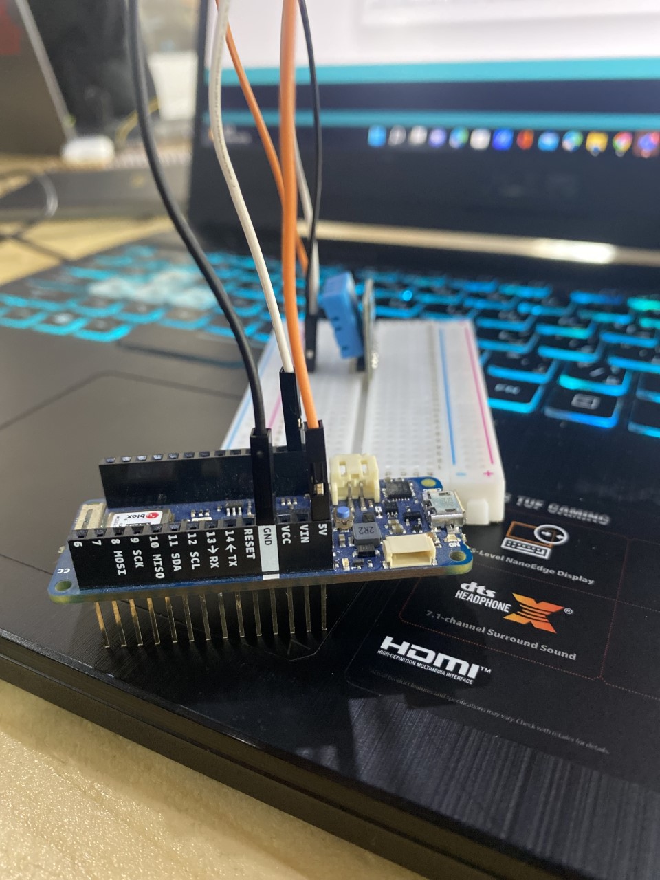
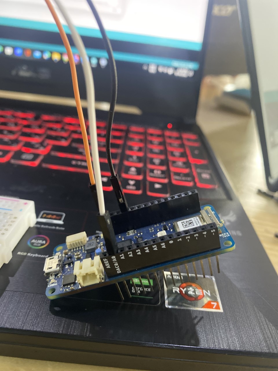
- This is the circuit, Black wire connected with GND, Orange wire connected with voltage, and the white one connected with A0 (analog).
Final result
Task2
-
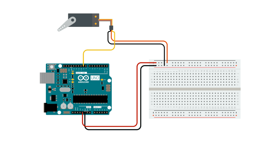
For ouput device I tried to play with servo motor.
-
Servo motors have three wires: power, ground, and signal. The power wire is typically red, and should be connected to the 5V pin on the Arduino board. The ground wire is typically black or brown and should be connected to a ground pin on the board. The signal pin is typically yellow or orange and should be connected to PWM pin on the board. In these examples, it is pin number 9.
- I choose sweep example and open the code from Aduino examples.
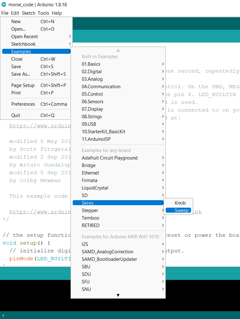
- This is code I used.
/* Sweep
 by BARRAGAN <http://barraganstudio.com>
 This example code is in the public domain.

 modified 8 Nov 2013
 by Scott Fitzgerald
 https://www.arduino.cc/en/Tutorial/LibraryExamples/Sweep
*/

#include <Servo.h>

Servo myservo;  // create servo object to control a servo
// twelve servo objects can be created on most boards

int pos = 0;    // variable to store the servo position

void setup() {
  myservo.attach(9);  // attaches the servo on pin 9 to the servo object
}

void loop() {
  for (pos = 0; pos <= 180; pos += 1) { // goes from 0 degrees to 180 degrees
    // in steps of 1 degree
    myservo.write(pos);              // tell servo to go to position in variable 'pos'
    delay(15);                       // waits 15 ms for the servo to reach the position
  }
  for (pos = 180; pos >= 0; pos -= 1) { // goes from 180 degrees to 0 degrees
    myservo.write(pos);              // tell servo to go to position in variable 'pos'
    delay(15);                       // waits 15 ms for the servo to reach the position
  }
}
Final result
Task 3
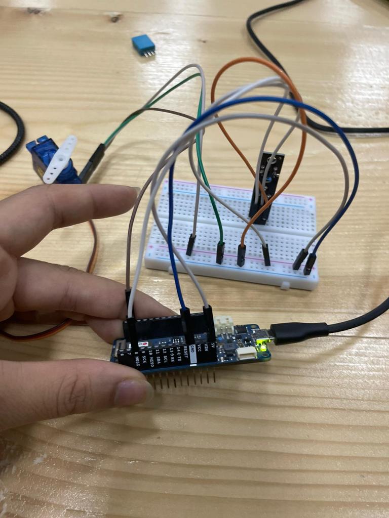
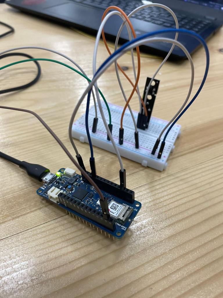
Combining input and output devices with the microcontroller and controlling the devices is the task at hand. My colleague Sadiq and I selected a tracking sensor for the input and a servo motor for the output device. When I put my hand in front of the motor, the programming I created causes it to rotate.
- This is the circuit that we designed.
- And this is the code we had useed.
#include <Servo.h>

Servo myservo;  // create servo object to control a servo
// twelve servo objects can be created on most boards

int pos = 0;    // variable to store the servo position
#define sensor 2
#define buzzer 3
#define red 4
#define green 5
int pot = 8;
void setup() {
Serial.begin(9600);
pinMode(sensor,INPUT);
pinMode(buzzer,OUTPUT);
pinMode(green,OUTPUT);
pinMode(red,OUTPUT);
Serial.begin(9600);
myservo.attach(4);  // attaches the servo on pin 9 to the servo object
}

void loop() {
bool value = digitalRead(sensor);
if(value == 0)
{
  digitalWrite(buzzer, HIGH);
    digitalWrite(green, HIGH);
      digitalWrite(red, HIGH);
  for (pos = 0; pos <= 180; pos += 1) { // goes from 0 degrees to 180 degrees
    // in steps of 1 degree
    myservo.write(pos);              // tell servo to go to position in variable 'pos'
    delay(15);                       // waits 15 ms for the servo to reach the position
  }
  for (pos = 180; pos >= 0; pos -= 1) { // goes from 180 degrees to 0 degrees
    myservo.write(pos);              // tell servo to go to position in variable 'pos'
    delay(15);                       // waits 15 ms for the servo to reach the position
  }
}
else
{
    digitalWrite(buzzer, LOW);
    digitalWrite(green, LOW);
      digitalWrite(red, LOW);
  }
Serial.print(digitalRead(8));
delay(500);
}
Final result