4. Embedded programming
Group Assessment
In this task we worked in two groups. One group researched about the types of microcontroller and another group researched about different programming languages. Our group worked on programming languages. We discussed four different languages in the table below.
C |
C++ |
Python |
MicroPython |
|
|---|---|---|---|---|
| Intro | Compiled language, very useful & powerful. Base for many scripting languages. Best choice for beginners | Compiled language, it has most or all elements of C. Supports different ways of programming like procedural, object-oriented. | A general-purpose interpreted, interactive, object-oriented, and high-level programming language. Excels in machine learning, AI, data analytics. | Runs on the bare metal of the microprocessors. Smaller version of Python standard library. |
| Pros | Efficient & widely used. Very less runtime. | Efficient & can save time in writing codes. | Open source, easy to learn. | Human readable, built-in exception and error handling. |
| Cons | Makes system insecure. | Most complicated | Not for real time operating systems | Takes more memory. No editor |
Table: Programming Languages.
Group Reference
Here I’m giving a link of the other group which conducted a study on the microcontrollers and their types.
Individual Assessment
Microcontroller specs and datasheet
For this assignment I used the Adafruit feathr express and the Adafruit feather sense. You can find their specs here and here. Both share the same microcontroller module nRF52840 on board. Find the datasheet here.
specs
- ARM Cortex M4F
- 1.7v to 3.3v operation
- BLE connection
- 21 GPIO, 6 x 12-bit ADC pins, up to 12 PWM outputs
Sense has the following additional sensors on board:
- ST Micro series 9-DoF motion - LSM6DS3TR-C Accel/Gyro + LIS3MDL magnetometer
- APDS9960 Proximity, Light, Color, and Gesture Sensor
- PDM Microphone sound sensor
- SHT Humidity
- BMP280 temperature and barometric pressure/altitude
Programming and setup
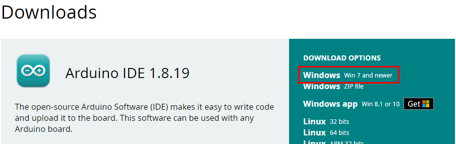
To program a micro-controller I downloaded the ‘Anduino IDE’ software and isntalled on my computer. Anduino IDE download link.
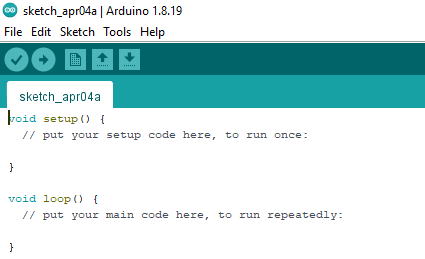
The workspace of the software appears as shown in the image below. The main screen shows the format of the software. First you setup the scope of your work/programming in the ‘void setup’. Second, you enter the code you want to run on repeat in a loop using ‘void loop’. Your code should be within the curly brackets { }.
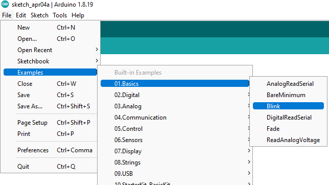
There are many different templates given. I started with the basic function which was blinking of the light on the controller.
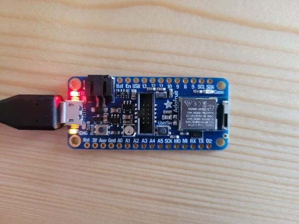
I was given an Adafruit micro-controller (nrf52840 feather) to start programming. A Board Support Package was installed following the guidelines from the page Arduino Support Setup. It is a board library to program the Adafruit controller.
Copy the code from the link given above and paste it in files>preferences>Additinal_Boards_Manager_URL. Next, I opened the boards manager from the ‘tools’, installed the ‘Adafruit nrF52’ and now adafruit board appears.
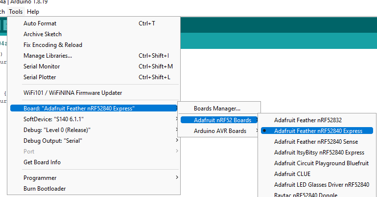
I linked my controller to the computer with a USB cable. And selected the ‘Port’ from ‘tools’ menu, for the given controller.
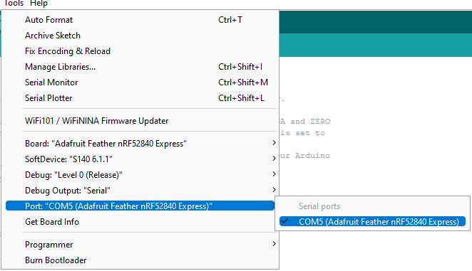
The ‘Port’ option didn’t appear for me at the beginning, so I reset the controller by double pressing the button besides the cable connection.
‘High’ and ‘Low’ text represents that light will turn ‘on’ and ‘off’ respectively. Its blinking time is managed by the command ‘Delay(time in milliseconds)’. Following coding was entered to make the LED blink.
// the setup function runs once when you press reset or power the board
void setup() {
  // initialize digital pin LED_BUILTIN as an output.
  pinMode(LED_BUILTIN, OUTPUT);
}

// the loop function runs over and over again forever
void loop() {
  digitalWrite(LED_BUILTIN, HIGH);   // turn the LED on (HIGH is the voltage level)
  delay(1000);                       // wait for a second
  digitalWrite(LED_BUILTIN, LOW);    // turn the LED off by making the voltage LOW
  delay(1000);                       // wait for a second
}
Morse Code Activity
We performed an activity were we translated some letters into the morse code using the Morse Code Translator. We used these translated codes and linked them with the blinking of the light on the controller. We set some rules for the activity which are shown in the table below. I used the morse code for the first four letters of my name.
![]()
| Ground Rules | |
|---|---|
| . | On for 1 second |
| - | On for 2 seconds |
| same letter space | Off for a half second |
| space b/w letters | Off for 2 seconds |
Here is the arduino code for the activity performed.
// the setup function runs once when you press reset or power the board
void setup() {
  // initialize digital pin LED_BUILTIN as an output.
  pinMode(LED_BUILTIN, OUTPUT);
}

// the loop function runs over and over again forever
void loop() {

  //Letter I
  digitalWrite(LED_BUILTIN, HIGH);   // turn the LED on (HIGH is the voltage level)
  delay(1000);                       // wait for a second
  digitalWrite(LED_BUILTIN, LOW);    // turn the LED off by making the voltage LOW
  delay(500);                       // wait for half a second

  digitalWrite(LED_BUILTIN, HIGH);   // turn the LED on (HIGH is the voltage level)
  delay(1000);                       // wait for a second
  digitalWrite(LED_BUILTIN, LOW);    // turn the LED off by making the voltage LOW
  delay(2000);                       // wait for 2 seconds
 //Letter F
  digitalWrite(LED_BUILTIN, HIGH);   // turn the LED on (HIGH is the voltage level)
  delay(1000);                       // wait for a second
  digitalWrite(LED_BUILTIN, LOW);    // turn the LED off by making the voltage LOW
  delay(500);                       // wait for half a second

  digitalWrite(LED_BUILTIN, HIGH);   // turn the LED on (HIGH is the voltage level)
  delay(1000);                       // wait for a second
  digitalWrite(LED_BUILTIN, LOW);    // turn the LED off by making the voltage LOW
  delay(500);                       // wait for half a second

  digitalWrite(LED_BUILTIN, HIGH);   // turn the LED on (HIGH is the voltage level)
  delay(2000);                       // wait for 2 seconds
  digitalWrite(LED_BUILTIN, LOW);    // turn the LED off by making the voltage LOW
  delay(500);                       // wait for half a second

  digitalWrite(LED_BUILTIN, HIGH);   // turn the LED on (HIGH is the voltage level)
  delay(1000);                       // wait for a second
  digitalWrite(LED_BUILTIN, LOW);    // turn the LED off by making the voltage LOW
  delay(2000);                       // wait for 2 seconds
//Letter T
  digitalWrite(LED_BUILTIN, HIGH);   // turn the LED on (HIGH is the voltage level)
  delay(2000);                       // wait for 2 seconds
  digitalWrite(LED_BUILTIN, LOW);    // turn the LED off by making the voltage LOW
  delay(2000);                       // wait for 2 seconds
//Letter I
  digitalWrite(LED_BUILTIN, HIGH);   // turn the LED on (HIGH is the voltage level)
  delay(1000);                       // wait for a second
  digitalWrite(LED_BUILTIN, LOW);    // turn the LED off by making the voltage LOW
  delay(500);                       // wait for half a second

  digitalWrite(LED_BUILTIN, HIGH);   // turn the LED on (HIGH is the voltage level)
  delay(1000);                       // wait for a second
  digitalWrite(LED_BUILTIN, LOW);    // turn the LED off by making the voltage LOW
  delay(500);                       // wait for half a second
}
Tinker cad Activity
We used tinker cad once again but this time to explore more about circuits. You can create new electronics circuit along with a very simple programming code. This code can be linked with Arduino IDE.
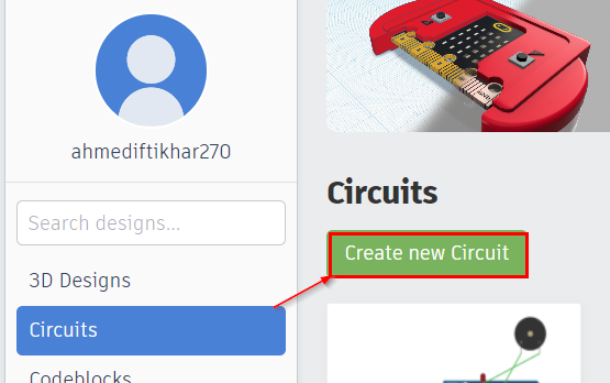
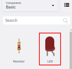
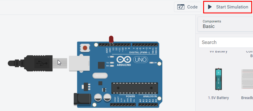
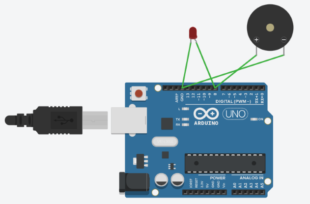
After selecting the ‘create new circuit’, I entered some basic components for the ‘Basic’ menu on the right. I performed the same activity of blinking the light but digitally using the tinker cad. I selected few basic components, which are LED, Piezo and Arduino Uno R3 and dragged them to the workspace one by one.

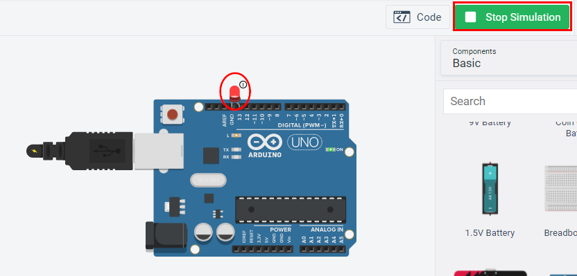
In the first step, I simply connected the cathode of the LED to the GND pin on the Arduino controller and anode of the LED to the pin 13 which is programmed to pass the current. To see the functioning of the controller I pressed ‘Stat Simulation’ button on the top right. Pressing the Simulation button stars blinking the LED in red colour.
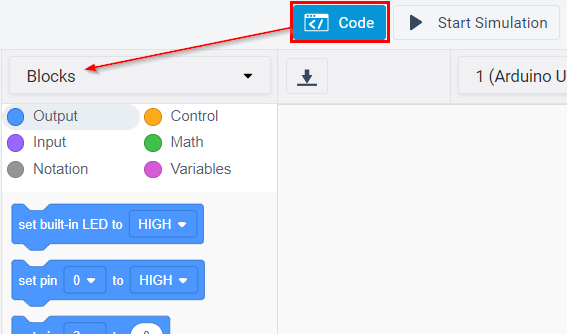
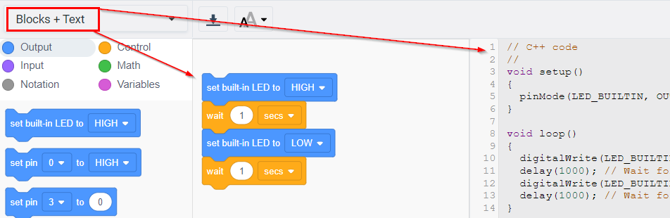
Along with the Simulation tab, you can see an option of ‘Code’ which provides you two different types of programming codes, ‘Blocks’ and ‘Text’. Blocks code is the code displayed in different colours (such as blue, purple, green, yellow etc). Each colour serves different actions in programming. For example, blue colour represents all the commands related to output. Text Code represents the same code as we saw in the Arduino IDE. You can design new circuits and copy their code to the arduino from the text section.
Exploring further, I searched the ‘Arduino Coffin Dance Code’ from the link and copy pasted it to the Text section in the Code tab. I attached an additional component Piezo to the controller. Piezo will produce the sound of the code alogwith the blinking LED Pin 8 was programmed for the current flow. The negative of the Piezo was attached to pin 8 and positive to the Ground pin (GND).
Hero video shot of the coffin dance arduino sound is shown below.
Mu Editor
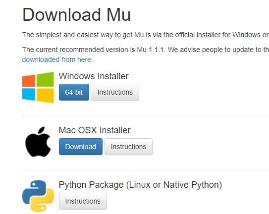
Mu is a simple code editor that works with the Adafruit CircuitPython boards. It’s written in Python and works on Windows, MacOS, Linux and Raspberry Pi. The serial console is built right in so you get immediate feedback from your board’s serial output!
Downloaded Mu editor
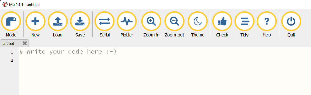
Mu editor works in the same manner as Arduino IDE but here you can write your code without worrying about the code layout. It manages the layout of your code using ‘Tidy’ option on the toolbar.
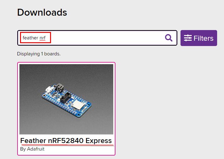
CircuitPython is a library of settings which help you program your controller in Mu editor. To download CircuitPython for my controller (Feather nRF52840 Express), I googled circuit python and opened the first link. Then searched for ‘Feather nRF52840 Express’ on the page and downloaded the .UFT file.
Then copy this downloaded .UFT file to the drive of the controller which enables Mu editor to write programs for the controller.
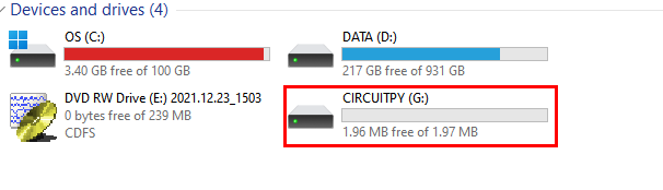
P.S ignore the drive C: running out of space.
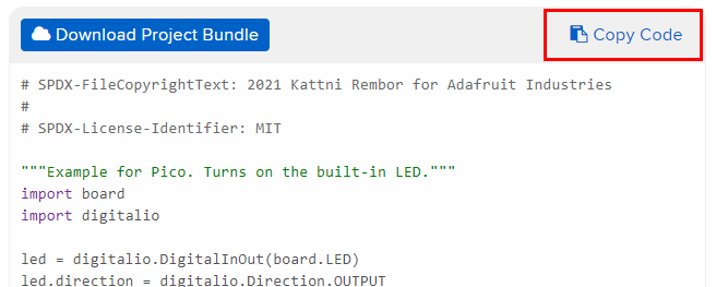 I googled the circuit python code for blinking the light on the controller and copy pasted it to the Mu editor. The code for it is given below. Code Link
# SPDX-FileCopyrightText: 2021 Kattni Rembor for Adafruit Industries
#
# SPDX-License-Identifier: MIT

"""Example for Pico. Turns on the built-in LED."""
import board
import digitalio

led = digitalio.DigitalInOut(board.LED)
led.direction = digitalio.Direction.OUTPUT

while True:
    led.value = True
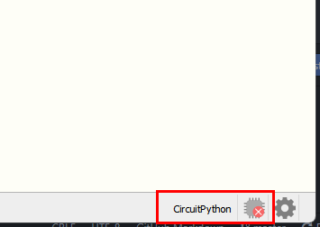
Connect the controller to your computer and run this code. If your controller is not connected or circuit python file for the controller is not the drive shown above, following error will appear at the right bottom of Mu editor screen.
Before running the code I used ‘Check’ option on the toolbar to see if the code has any mistakes.
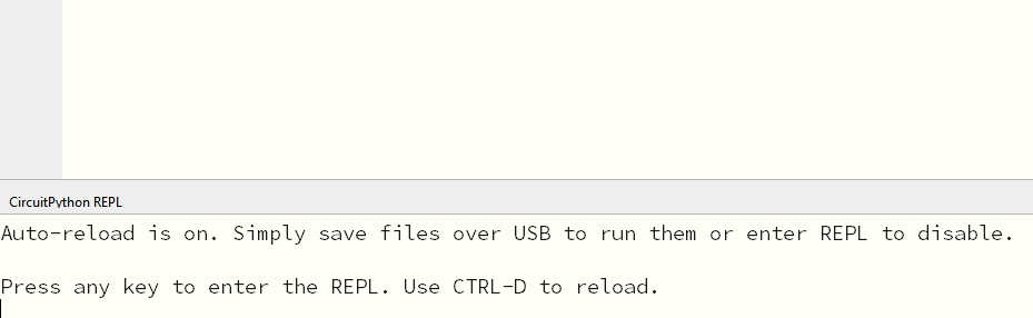
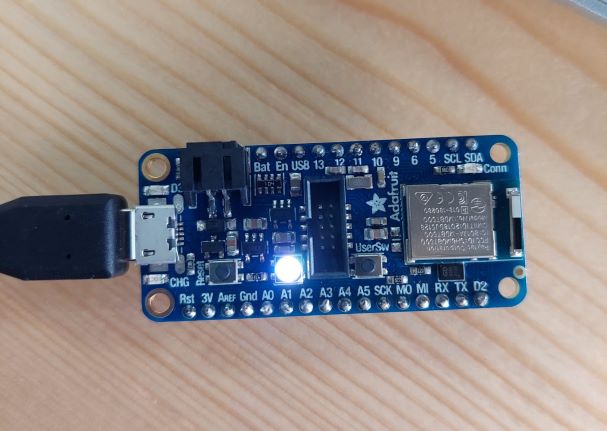
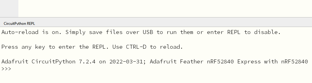 Then I used ‘Serial’ option to run the code and a new window (CircuitPython REPL) appears at the bottom of the editor. Press any key and you are connected to the controller directly. White light on my controller starts glowing.
Soldering
At the end of this week, I learned about soldering the adafruit microcontroller which I programmed at the beginning of this week. Following tools were used while soldering:
| Tools | Functions |
|---|---|
| Soldering Gun | provides heat to melt the wire. |
| Soldering Wire | melted wire by the gun, provides a joint of pin with the board. |
| Smoke/Fume Absorber | absorbs the fume due to burning of the wire, so that you don’t inhale it. |
| Desoldering Pump | helps you the solders |
| Ligh Bulb | over your workspace gives you a clear vision while working |
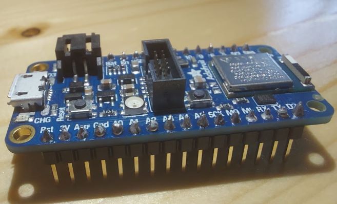
I soldered both sides of the controller with 16 pins on one side and 12 pins on the other side.
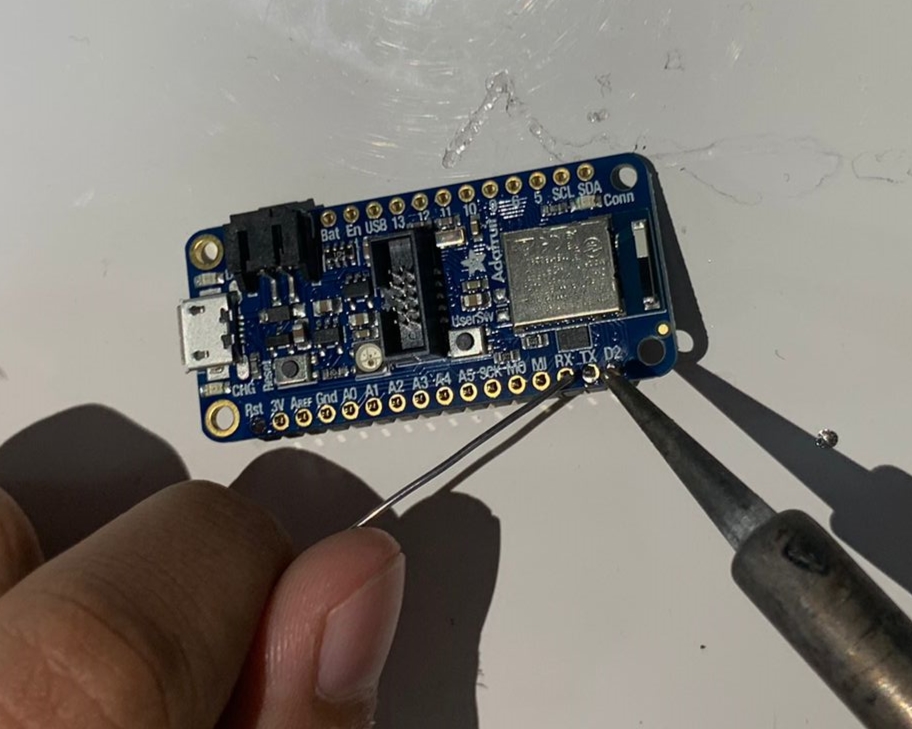
It was my first time soldering thus some irregularities can be seen on the controller.
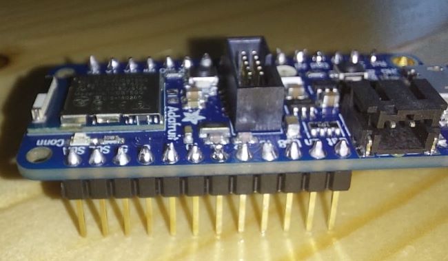
Some of the bad soldered pins were removed with the help of desoldering pump.
Comments
I have enjoyed learning about programming in this week. I have always admired this work of programming. But never gave it much time on learning myself. In his week, I got introduced to different platforms which are useful in the programming world. I learned about soldering a circuit board at the end of the week. It was an exciting session I was struggling at the beginning but I would love to that again.