3. Computer controlled cutting
This week we were introduced to digital fabrication by learning about its associated machines. When it comes to manufacturing there are two main types:
-
Additive: A great example of this is the 3D printer. Were you feed it plastic and its dissolves to form your design. A great disadvantage of this type of manufacturing is that it produces a lot of waster material compared to the other type.
-
Subtractive: The CNC and laser cutter use this type of manufacturing to cut out/engrave or score the design onto the material supplied.
Group Assignment
For this weeks group assignment we were all tasked to test out different chracteristics and features of the laser cutter before we were to begin desgining and laser cutting. I was tasked with determining the Power and Speed that would be optimal for laser cutting on a 2.9mm cardboard. Sayed Qasim was to test out the laser cutter’s Focus. Fareed was to test out both the Frequency and Kerf and Jasim Al-Thawadi was tasked with testing the joint clearance. All integral and important parts to test out before we begin our desgin process. Below are the results of all experimentation in respective order:
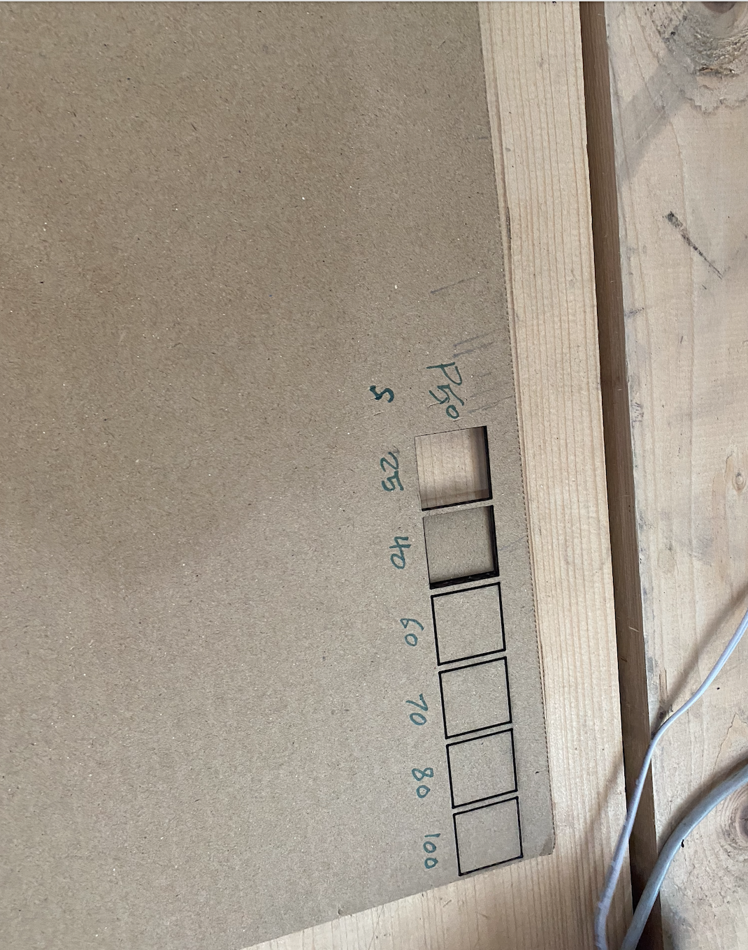
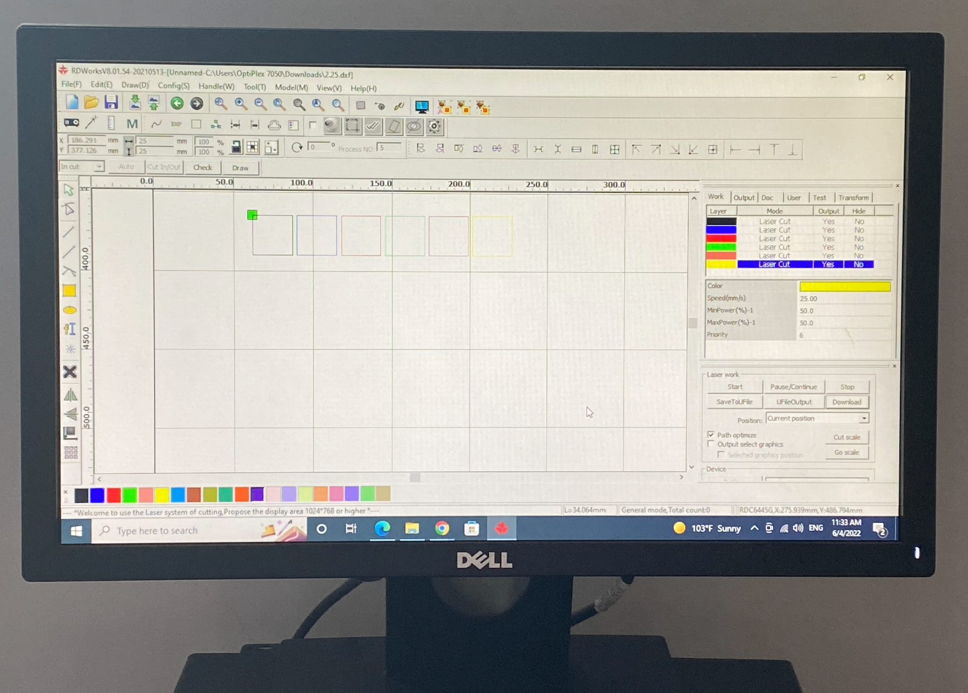
Steps to test the laser cutter's power and speed:
To summarize it's mostly trial and error. You'll need to place different values for the power and speed to find the perfect value that leaves you with no charing or uneven cutting.
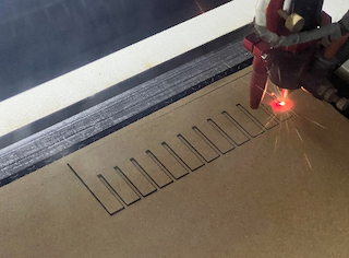
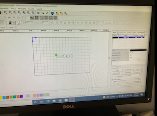
1. Begin with drawing a single square
2. Use the array icon at the bottom left of the screen and set your desired number of rows and spacing and make sure to leave an adequate amount of spacing between the objects
3. Assign different colors to each square to allow for easier manipulation of the power, speed and other properties
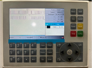
4. For our material (2.9mm thick cardboard) we set the power at 50% for all the squares and used different values for the speed (25,40,60,80,100)
5. Send the design over to the machine and begin the cutting process
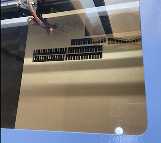
6. After it was done, and after making careful observations we decided that the power at 50% and speed at 25mm/second was the optimum power and speed for this machine for the 3mm cardboard material that we were planning to use
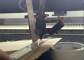
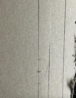
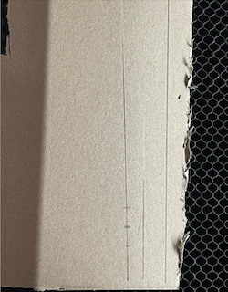
Steps to test the laser cutter's Focus:
1- I searched on the internet about the focus of a laser cutter and saw examples of how to do the test.2- I took a piece of carton and put it in the machine but I put also on the edge of the piece an object to make the carton italic.
3-Then I used the laser cutter to cut a straight line
4-I measure the distance between the point that has the highest depth and the machine to find the focus.
Frequency : -
The higher the frequency the lower the quality of the cut depending on the type of material used. Measured in parts per inch (ppt). Generally, for harder materials such as wood, lower frequencies are needed below 500 ppt. If higher frequencies are used for wood, it might cause charring or start of fire, which is to be avoided. However, for thinner materials with less hardness such as Plastics/Acrylic, higher frequencies can be used usually ranging from 3.5k ppt to 5k ppt for a clean finish cut.
Steps to test the laser cutter's Frequency:
To test the above-mentioned values, a material can be tested using different frequencies with caution of fire. The result is to identify whether the frequency is appropriate or not based on how the cut looks? Is it clean? Are there burns or charring? Then the ones with the most satisfactory results are to be considered appropriate.Kerf: -
Kerf is the amount of material cut using the laser cutter. In Other words, it is the width of the laser flow that takes from the material while cutting. It is important to know such width for proper fixture of joints and assembly of cut parts.
Steps to test the laser cutter's Kerf :
To test such value: - 1. A normal square with random dimension is to be drawn in any software such as cuttle and cut using the laser machine.2. The square is then to be measured using an accurate measuring tool, preferably a digital caliper showing at least two decimal places of a millimeter unit.
3. The kerf is to be calculated by subtracting the cut width from the original designed width.
4. Now the kerf compensation is to be found sinch the laser cutter cuts the material from both sides meaning the kerf value needs to be divided into 2 which gives the kerf compensation.
Original width = 4mm
Kerf = 4 – 3.95 = 0.05
Kerf Compensation = 0.05/2 = 0.025mm
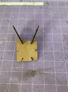
Clearance: One of the important parts to create a parametric construction kit is the clearance. To attach to two parametric construction kit, the size of the joint must be known to get the best fit. To get the suitable joint clearance, a design that looks like a hair comb was made were the distance between the teeth has different space as it can be seen bellow: -
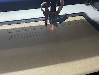
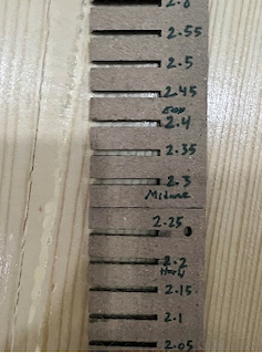
Steps to test the laser cutter's joint clearance:
The space size between the testing specimen teeth starts from 2.9mm to 2.3mm on one testing specimen, while the second specimen start form 2.25mm to 1.65mm.Two specimens where cut from each size, so each size will check to be fit with the same size. For example, testing the teeth size 2.5mm with teeth size 2.5mm. Starting from the largest teeth and ending by the size where the teeth cannot be joined together, the teeth size 2.45mm and larger found very loose while the sizes that less than 2.15mm found very tight.
Therefore, it is found the best sizes for the clearances are between 2.2mm to 2.4mm, where 2.2mm will provide slightly tight fixing without causing damage to the material, 2.3mm is a medium tightness that allows the joint to be fit more easily than 2.2mm, and finally, 2.4mm considered as the easiest joint fixing while it will not be very loose as it can be seen in the following photo.
Tips and Tricks for using the laser cutter
- make sure to be familiar with its safety precautions
- never leave the machine unattended
- the RDWorks software is intended for basic designs such as circles, rectangles and squares.
My Parametrically designed Polygons
I decided to use Fusion 360 and Cuttle to simply sketch out circles, squares and triangles and then apply my constraints onto them.
Steps on how I produced my parametric press fit design:
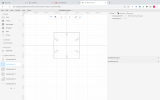
1. I used the software cuttle and added the circle, rectangle and polygon shape onto my design surface
2. I set the length for my shapes as 50mm which corresponds to 5cm
3. I set the width of my rectangle outline as 2.2mm which based on the fit test was the most accurate when it came to joint fit.
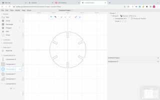
4. I used the rotation repeat tool to allow for faster indentation of the rectangle into the circle, triangle and squares.
5. After placing the rectangles all around the shapes, I used the boolean difference tool to indent the rectangle into the shapes to act as a skit.
6. After I was satisfied with the design I exported it as a SVG file and then opened it in Inkscape
7. In Inkscape I saved the same file as a DXF and emailed it to the email address which is associated with the computer
8. After setting the array at my preferred number of rows and columns I went ahead and printed the design in the laser cutter
9. After an initial testing, I was then able to batch produce my shapes along with my other classmates.
After placing the square and circle into the space I added the rectangles in the square by using the rotational repeat extention and the boolean difference tools.
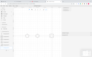
After all the shapes were indented with the rectangle I added all the images into a separate surface to export them as an SVG
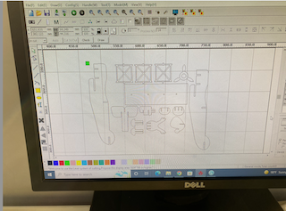
Finalizing the design on RDWorks to be sent to the machine for testing
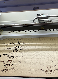
The laser cutter cutting off the testing pieces of the press fit design
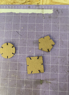
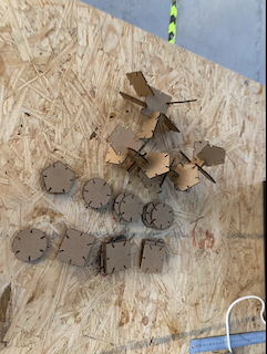
After inspecting the tester pieces (displayed above) and confirmed that the joints fit perfectly, We went ahead and batch printed a large amount of the pieces based on the same power and speed
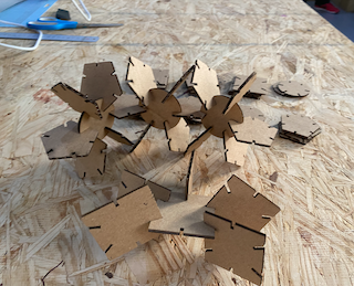
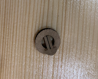
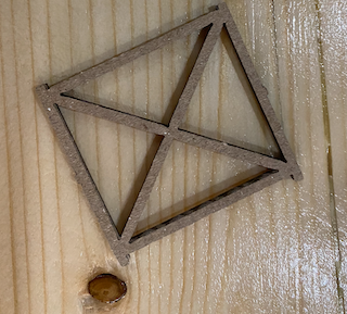
Heroshot of the Polygons :
Parametric Press fit Polygons Design File
My Parametrically designed Airplane
Following the success that I encountered with designing and laser cutter the polygons I decided to take on a bigger challenge. I planned to laser cut a sketch on an airplane that I had seen on pinterest and that caught my eye.
Detailed steps on how I designed and executed the parametric press fit Airplane:
1. After locking in on my preferred choice of aircraft I begin with tracing the outline in Fusion 360.2. Quickly enough I realized that changing the dimension would a hassel and changed my choice of software to cuttle
3. For the wheels and the wings, Cuttle was magic. I added my initial circle and rectangle with my preffered dimentions and locked them in
4. For the more complex shapes such as the joints and the connectors I decided that tracing the outline would be the easiest and the quickest route
5. I used Shaper3D on my ipad as well as Fusion 360 to create those pieces
6. Finally when I was satisfied with the design I decided to laser cut a few samples just so that I had a better visualization on how the joints fit
7. Unfortunately the joint between the wings and the columns was too small and I had to reconsider the dimensions
8. I used cuttle to quickly fix this issue and thankfully everything went well after that
9. For my last step, I printed out all the remaining pieces and they all fit well
After completeing my designing I sent them over to RDWorks to be printed on the laser cutter
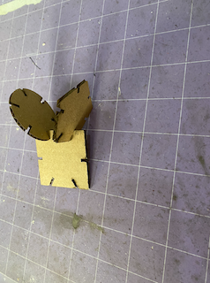
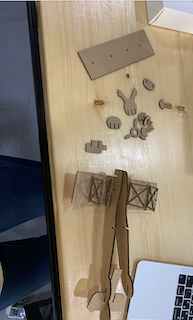
Here are some of the first pieces that I used as to test the joints
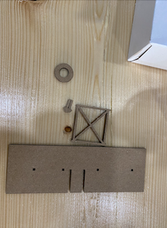
This wheel, connectors and the windows were the wrong size and I needed to double check my measurements
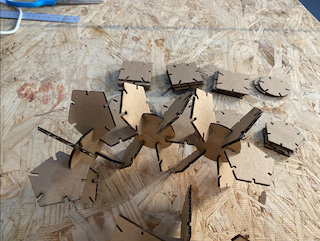
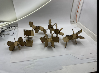
Here are some pictures as of me assembling my airplane
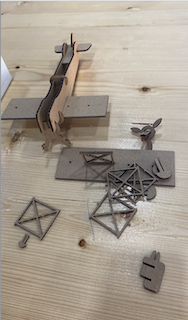
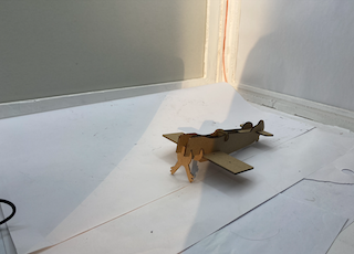
Hero shot of the Airplane:
Link to my design file for the windows and connector
Link to the front piece design file
Link to the design file of the pieces I traced
Link to the corrected measurements of the missing pieces of the airplane
Vinyl Cutting
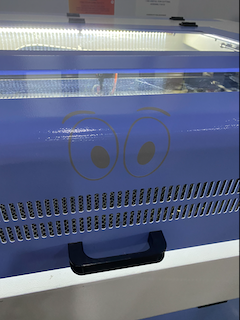
Essentially where we used the vinyl Cutter ‘Cricut’ to produce our very own stickers. I decided to add a eyes to the laser cutter in the form of a sticker.
Detailed Steps on how to use 'Cricut':
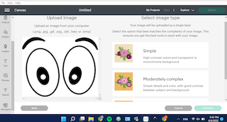
1. Begin with choosing an image in png format
2. Send the desired image as a png format to the dedicated email address provided by the fab lab instructor
3. Once uploaded on the 'Cricut' software from the designated computer, Follow the instructions provided by the computer
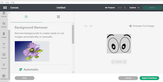
4. Remove any background whites in order to receive a clean sticker
5. Once you're happy with all the changes proceed to printing the sticker
6. Place the mat on the starting point on the device and begin printing
7. Once its done printing, remove any excess vinyl that you wont need with a tweezer
8. Transfer the sticker onto a transparent paper
9. Position the sticker onto the surface/ location of your choosing and you're done
I sent the eye image as a png to the computer connected to ‘Cricut’ as shown below:
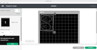
After confirming that the image was successfully uploaded I selected the area that I wanted to be printed:
The grey vinyl was limited therefore to save space when printing I rotated the image 90 degrees to fit the vinyl:
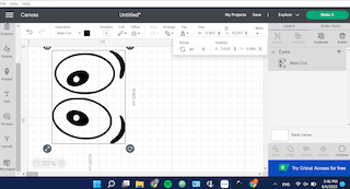
Below is the selected area before I printed it out:
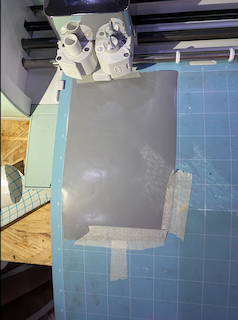
The initial placement of the vinyl on ‘Cricut’

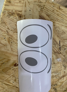
After the machine printed the image onto the vinyl I removed all the excess vinyl
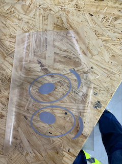
Transferring the sticker onto a transparent paper which allowed for a more efficient transferring method of the sticker
Before Placing the sticker I measured out the approximate location that I would want to place it on the laser cutter
Heroshot of the Sticker: