7. Input & Output device
Inputs and Outputs
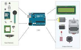
The arduino pins can be used as an input and output. The arduino can output either a digital signal or a PWM signal, Also the input can be digital or analog. A relation can be defined in the code between the input and output to make very easy, cheap and accurate controls.
Input and output devices are used to allow the arduino to interact with the enviroment, like reading temperture and humedity or controlling a motor or an led.
signals types
I used a microphone module, it has an analog and digital outputs.
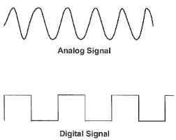
Analog signals could be any value which is limited in the arduino in range from 0 to 5v which is repersented as a value form 0 to 1023 since it has a 12 bit Analog to digital converter. In this case the analog signal is the sound coming from the microphone.
Digital signals either have a value of 0 or 5v which is repersented by a binary 0 or 1. In the microphone module case the digital output is a analog signal got converted by a comparetor. if the signal is above the threshold voltage form the small potenchameter the digital signal become 5v or a binary 1 otherwise it is 0v or binary 0.
Actual circuit
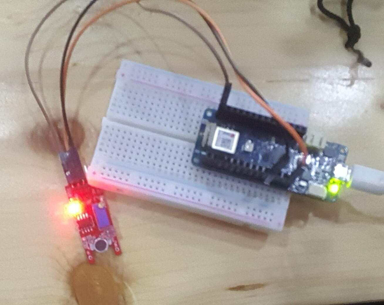
I used the arduino to calculate the frequency of the sound then toggle the led if the frequency is in the whistle frequency range.
code
#define mic 5
int maxfreq = 2000,minfreq = 900;
int state = 0;
bool New = true;
void setup() {
  // put your setup code here, to run once:
  pinMode(LED_BUILTIN, OUTPUT);
  pinMode(mic, INPUT);
}

void loop() {
  // put your main code here, to run repeatedly:
  int freq = 1/(pulseIn(mic,HIGH));
  if(freq > minfreq && freq < maxfreq && New){
      if(state == 1){state = 0;}else{state = 1;}
      New = false;
    }else{
      New = true;
    }
  digitalWrite(LED_BUILTIN,state);


}
RGB led group assignment
In the group assignment we controlled an RGB LED using a pwm signal from an arduino board.
PWM is stands for Pulse Width Modulation which is a signal has an average value that can varies between 0 to 5 volts.
RGB led is an led that has red, green and blue led chips in one package.
RGB led are available in two configurations
1- common anode: where leds positive sides are connected together. While the negative side is connected to the control signal for each one.
2- common cathode: where leds negative sides are connected together. While the positive sides is connected to the control signal for each one.
*Note that the voltage in the anode must be higher than the cathode in order for the led to turn on.
Since we have a common anode configuration (the led pcb silck screen was wrong) We connected the common to 5v and the R, G and B pins are connected to the arduino pins with PWM ability using a resistor to limit the current.
If the signal pin is high the led will be off since the voltage difference is 0v across the led
If the signal pin is low then the led will be on since the voltage across it is 5v(resistor included).

now if we turn the led on and off very fast we can control the led brightness be varying the on and off time.
For example for equal in and off times the led will have average voltage of 2.5 and glow with half of the brightness and this what pwm do.
PWM signal can be generated by using the function analogWrite();
The function takes two parameters the first one is the pin number and the second is a value from 0 to 255.
codes
#define Rpin 3
#define Gpin 4
#define Bpin 5

int r = 128, g =50 , b = 0;

void RGB(int r, int g, int b){
    r = 255 - r;
    g = 255 - g;
    b = 255 - b;
    analogWrite(Rpin, r);
    analogWrite(Gpin, g);
    analogWrite(Bpin, b);
}

void setup(){
   pinMode(Rpin,OUTPUT);
   pinMode(Gpin,OUTPUT);
   pinMode(Bpin,OUTPUT);

   RGB(255,0,0);//RED
   delay(1000);
   RGB(0,255,0);//Green
   delay(1000);
   RGB(0,0,255);//Blue
   delay(1000);
}

void loop() {

}
To make the fading effect the value should change from 255 to 0 and then to 255 again.
In order to do that void loop used like this:
#define Rpin 3
#define Gpin 4
#define Bpin 5

int r = 0, g =0 , b = 0;

void RGB(int r, int g, int b){
    r = 255 - r;
    g = 255 - g;
    b = 255 - b;
    analogWrite(Rpin, r);
    analogWrite(Gpin, g);
    analogWrite(Bpin, b);
}

void setup(){
   pinMode(Rpin,OUTPUT);
   pinMode(Gpin,OUTPUT);
   pinMode(Bpin,OUTPUT);

   RGB(255,0,0);//RED
   delay(1000);
   RGB(0,255,0);//Green
   delay(1000);
   RGB(0,0,255);//Blue
   delay(1000);
}

int fadeAmount = 1;
int Brightness = 0;

void loop(){
  Brightness += fadeAmount;
  if(Brightness>=255 || Brightness<=0){
    fadeAmount = -fadeAmount;
  }
  RGB(100, Brightness, 0);
  delay(10);
}