7. Input & Output device
This week we were assigned to learn about input and output devices I used Arduino Adafruit Feather nRF52840 as the microcontroller and Arduino IDE for the programming (same as I used for week 4 embedded programming)
Output
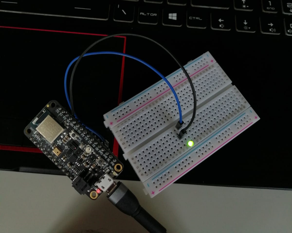
Firstly, I wanted to learn how to do basic programming and stuff so I configured a LED light as an output device
This website helped me do the process
This is the code I used
#define LED 13

void setup() {
pinMode(LED,OUTPUT;

}

void loop() {
digitalWrite(LED,High);

}
Outcome
I learned that input devices are just meant to be physical goods for us to use but the computer deals with them as data of true and false 0,1 or range of data And the outputs are display methods that are used to transfer a data from the computer towards the physical world
Input & Output
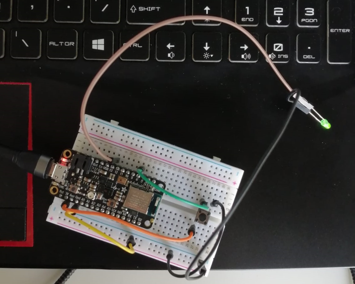
Then, I wanted to incorporate input devices so I added a push button and programmed it so the LED light will work if the button is pressed
This website helped me do the process
This is the code I used
const int buttonpin = 5;
const int ledpin = 13;

int buttonstate = 0;

void setup() {
pinMode(ledpin,OUTPUT);
pinMode(buttonpin,INPUT);
}

void loop() {
buttonstate = digitalRead(buttonpin);
if(buttonstate == High){
  digitalWrite(ledpin, HIGH);
} else {
  digitalWrite(ledpin, LOW);
}
}
Outcome
Challenge
Use the one of the sensors on the Adafruit & try to program to display its results in the serial monitor + to be represented by an LED &/or Buzzer
So I wanted to use the temperature sensor thus I made the embedded LED light of the Adafruit glow when the temperature reaches 30+ degree while showing the readings on the serial monitoring This is the code I used
/***************************************************************************
  This is a library for the BMP280 humidity, temperature & pressure sensor
  Designed specifically to work with the Adafruit BMP280 Breakout
  ----> http://www.adafruit.com/products/2651
  These sensors use I2C or SPI to communicate, 2 or 4 pins are required
  to interface.
  Adafruit invests time and resources providing this open source code,
  please support Adafruit andopen-source hardware by purchasing products
  from Adafruit!
  Written by Limor Fried & Kevin Townsend for Adafruit Industries.
  BSD license, all text above must be included in any redistribution
 ***************************************************************************/

#include <Wire.h>
#include <SPI.h>
#include <Adafruit_BMP280.h>

#define BMP_SCK  (13)
#define BMP_MISO (12)
#define BMP_MOSI (11)
#define BMP_CS   (10)


Adafruit_BMP280 bmp; // I2C
//Adafruit_BMP280 bmp(BMP_CS); // hardware SPI
//Adafruit_BMP280 bmp(BMP_CS, BMP_MOSI, BMP_MISO,  BMP_SCK);

void setup() {
  pinMode(LED_BUILTIN, OUTPUT);


  Serial.begin(9600);
  while ( !Serial ) delay(100);   // wait for native usb
  Serial.println(F("BMP280 test"));
  unsigned status;
  //status = bmp.begin(BMP280_ADDRESS_ALT, BMP280_CHIPID);
  status = bmp.begin();
  if (!status) {
    Serial.println(F("Could not find a valid BMP280 sensor, check wiring or "
                      "try a different address!"));
    Serial.print("SensorID was: 0x"); Serial.println(bmp.sensorID(),16);
    Serial.print("        ID of 0xFF probably means a bad address, a BMP 180 or BMP 085\n");
    Serial.print("   ID of 0x56-0x58 represents a BMP 280,\n");
    Serial.print("        ID of 0x60 represents a BME 280.\n");
    Serial.print("        ID of 0x61 represents a BME 680.\n");
    while (1) delay(10);
  }

  /* Default settings from datasheet. */
  bmp.setSampling(Adafruit_BMP280::MODE_NORMAL,     /* Operating Mode. */
                  Adafruit_BMP280::SAMPLING_X2,     /* Temp. oversampling */
                  Adafruit_BMP280::SAMPLING_X16,    /* Pressure oversampling */
                  Adafruit_BMP280::FILTER_X16,      /* Filtering. */
                  Adafruit_BMP280::STANDBY_MS_500); /* Standby time. */
}

void loop()
{
if (bmp.readTemperature() > 30) {
// turn LED on:
  digitalWrite(LED_BUILTIN, HIGH);   // turn the LED on (HIGH is the voltage level)
} else {
  digitalWrite(LED_BUILTIN, LOW);   // turn the LED on (HIGH is the voltage level)


    Serial.print(F("Temperature = "));
    Serial.print(bmp.readTemperature());
    Serial.println(" *C");

    Serial.print(F("Pressure = "));
    Serial.print(bmp.readPressure());
    Serial.println(" Pa");

    Serial.print(F("Approx altitude = "));
    Serial.print(bmp.readAltitude(1013.25)); /* Adjusted to local forecast! */
    Serial.println(" m");

    Serial.println();
    delay(2000);
}
}
One of the problems I faced is that the microcontroller was disconnecting every time I wanted to test so I needed to reconnect the microcontroller to the PC and join it again. Another problem is that at first I did not put a delay on the code therefor I couldn’t tell if the reading was correct or not because I was not able to see the changes. However, after putting the delay I was able to physically see the changes of the readings.
Outcome