5. Embedded programming
for this week, we are working on Microcontroller which is a small and low cost computer that have CPU inside to be programmed on doing specific tasks, example on microcontroller chip is: receiving remote signals or displaying refrigerator, freezer, A/C, microwave…etc information. Essentially, a microcontroller works to gather input, process the information, and output a particular action based on the information gathered.
Group Assignment
for our grope assignment, we are searching about the different types of microcontrollers and to know what is our type. for more information please check out this link : Microcontroller.
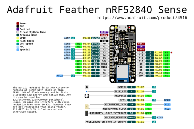
Adafruit Feather Bluefruit Sense
The Adafruit Feather Bluefruit Sense AKA Feather nRF52840 Express is the type of microcontroller that i picked. This Feather microcontroller comes with Bluetooth Low Energy and native USB support featuring the nRF52840! This Feather is an ‘all-in-one’ Arduino-compatible + Bluetooth Low Energy with built in USB plus battery charging. With native USB it works great with CircuitPython, too.
Arduino
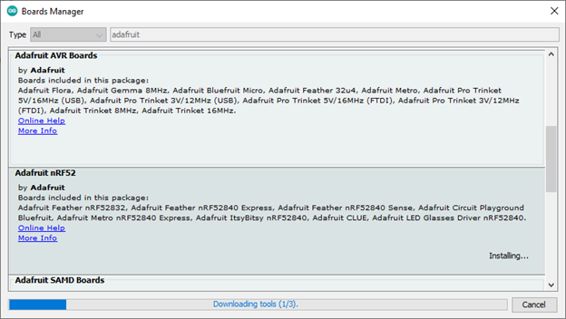
To program the microcontroller, we used a software which is called Arduino but first you need to connect the program and connect it to the same name as the microcontroller that you are using which the installation and connecting steps can be found in this link Arduino setup. The picture below is the installation process which will take time to fully install.
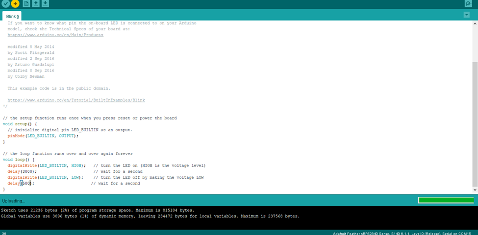
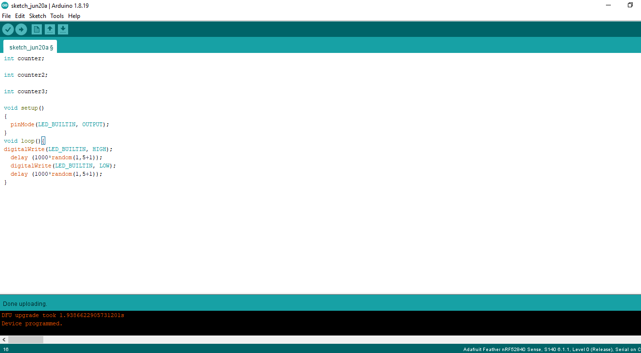
for our first exercise, we programmed the microcontroller to blink for 1 second on and 1 second off and then i changed the timing of the blink to test and learn how to use Arduino so i changed the timing to 3 seconds on and 0.5 second off. HIGH=on, LOW=off
// the setup function runs once when you press reset or power the board
void setup() {
  // initialize digital pin LED_BUILTIN as an output.
  pinMode(LED_BUILTIN, OUTPUT);
}

// the loop function runs over and over again forever
void loop() {
  digitalWrite(LED_BUILTIN, HIGH);   // turn the LED on (HIGH is the voltage level)
  delay(3000);                       // wait for a second
  digitalWrite(LED_BUILTIN, LOW);    // turn the LED off by making the voltage LOW
  delay(500);                       // wait for a second
}
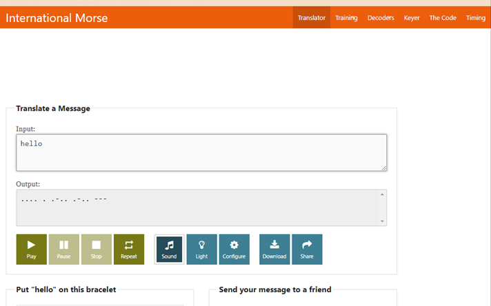
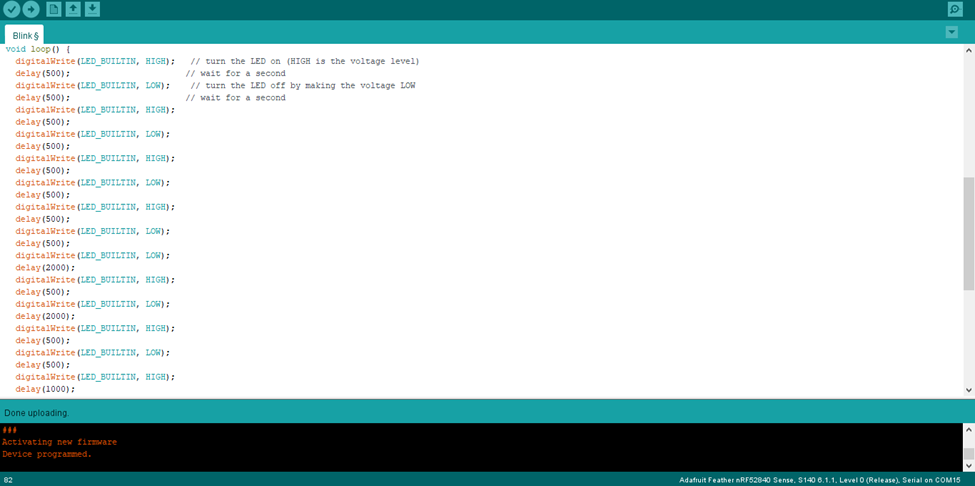
for the second exercise, we programmed the light to blink a word of our choosing using the Morse code so i picked the word “hello” and translated it to morse code using this website Morse Code Translator and the translation is shown below:
fablab have a basic rules for Morse code programing which is:
-
0.5 second for dot
-
1 second for dash
-
0.5 second between each dot or dash
-
2 seconds between letters
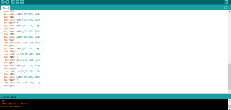
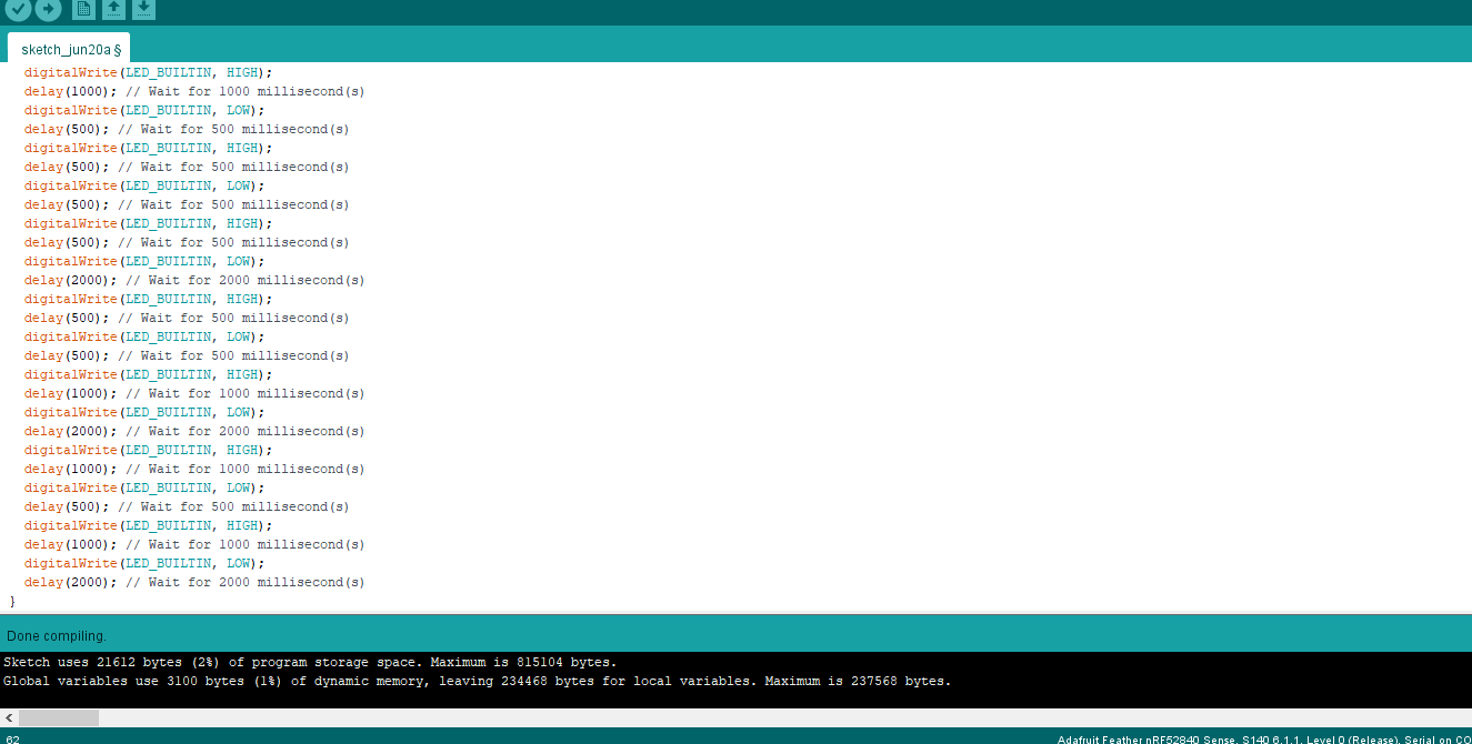
the code for the word “hello” is shown below:
void setup() {
  // initialize digital pin LED_BUILTIN as an output.
  pinMode(LED_BUILTIN, OUTPUT);
}

// the loop function runs over and over again forever
void loop() {
digitalWrite(LED_BUILTIN, HIGH) ;
delay (500) ;
digitalWrite (LED_BUILTIN, LOW) ;
delay (500) ;
digitalWrite(LED_BUILTIN, HIGH) ;
delay (500) ;
digitalWrite(LED_BUILTIN, LOW) ;
delay (500) ;
digitalWrite(LED_BUILTIN, HIGH) ;
delay (500) ;
digitalWrite(LED_BUILTIN, LOW) ;
delay (500) ;
digitalWrite(LED_BUILTIN, HIGH) ;
delay (500) ;
digitalWrite(LED_BUILTIN, LOW) ;
delay (2000) ;
digitalWrite(LED_BUILTIN, HIGH) ;
delay (500) ;
digitalWrite(LED_BUILTIN, LOW) ;
delay (2000) ;
digitalWrite(LED_BUILTIN, HIGH) ;
delay (500) ;
digitalWrite(LED_BUILTIN, LOW) ;
delay (500) ;
digitalWrite(LED_BUILTIN, HIGH) ;
delay (1000) ;
digitalWrite(LED_BUILTIN, LOW) ;
delay (500) ;
digitalWrite(LED_BUILTIN, HIGH) ;
delay (500) ;
digitalWrite(LED_BUILTIN, LOW) ;
delay (500) ;
digitalWrite(LED_BUILTIN, HIGH) ;
delay (500) ;
digitalWrite(LED_BUILTIN, LOW) ;
delay (2000) ;
digitalWrite(LED_BUILTIN, HIGH) ;
delay (1000) ;
digitalWrite(LED_BUILTIN, LOW) ;
delay (500) ;
digitalWrite(LED_BUILTIN, HIGH) ;
delay (1000) ;
digitalWrite(LED_BUILTIN, LOW) ;
delay (500) ;
digitalWrite(LED_BUILTIN, HIGH) ;
delay (1000) ;
digitalWrite(LED_BUILTIN, LOW) ;
delay (2000) ;
}
TinkerCAD
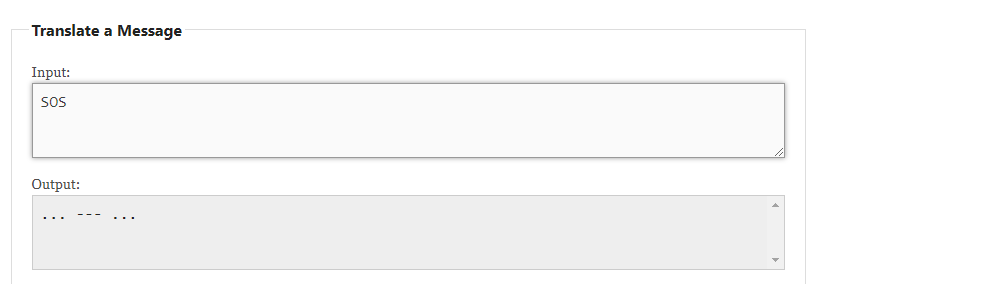
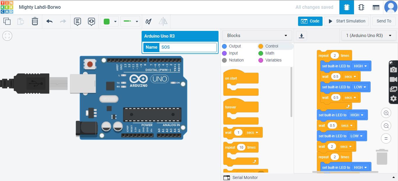
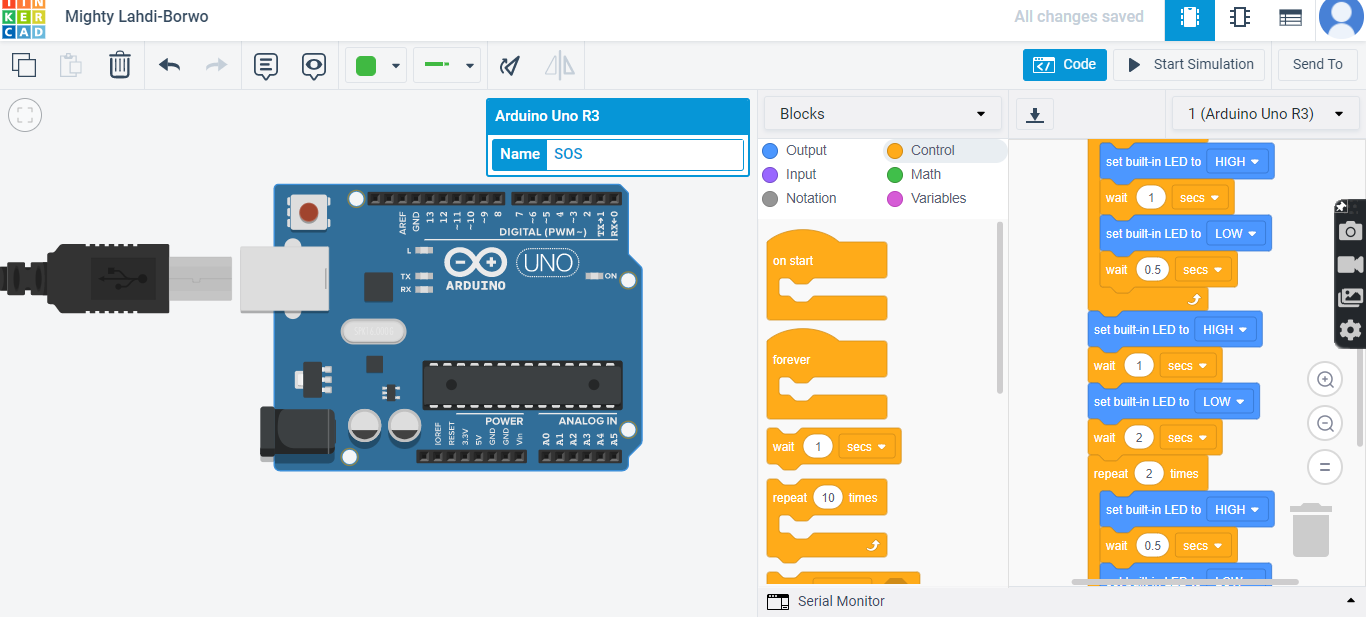
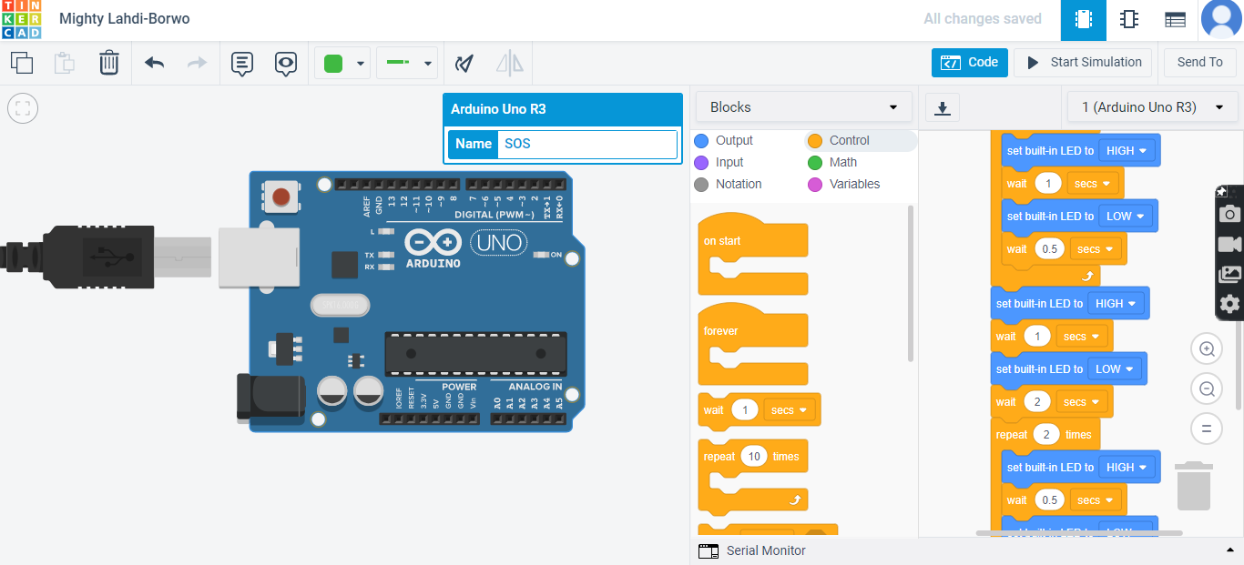
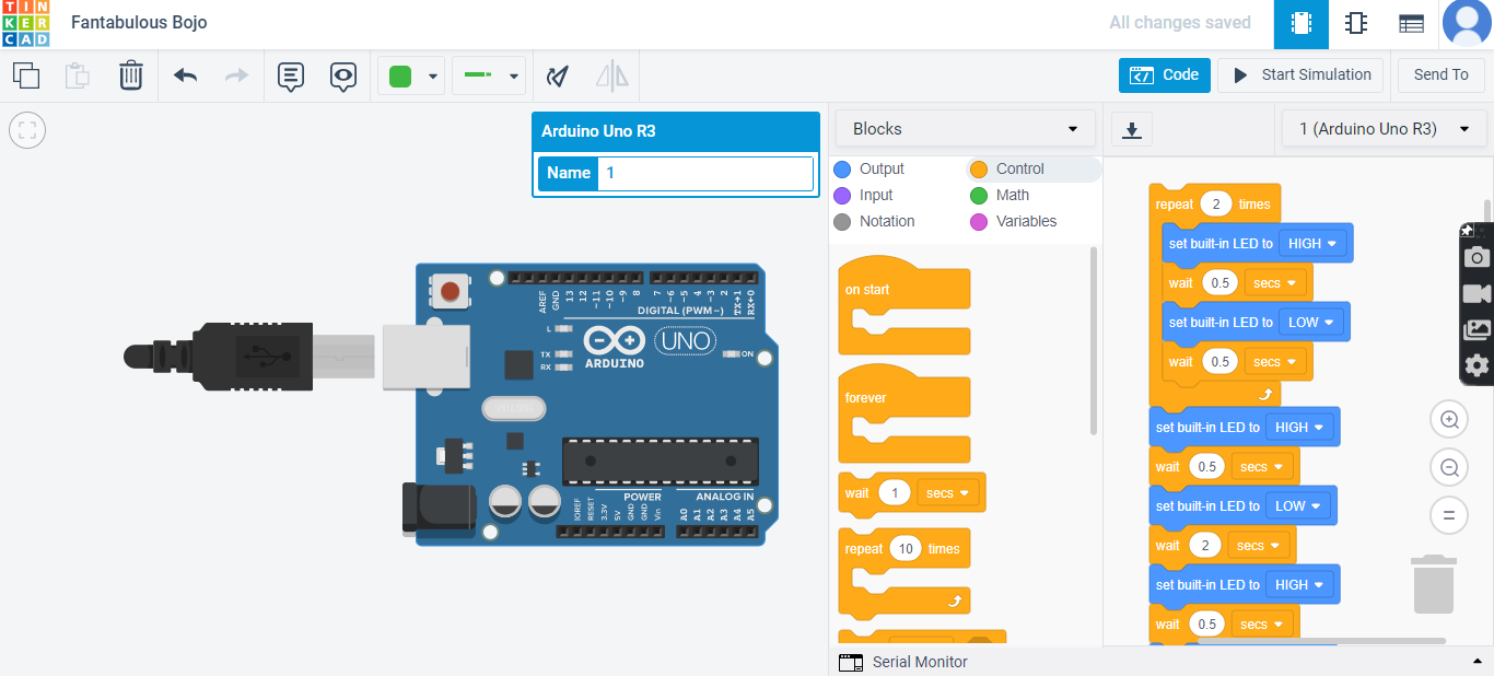
TinkerCAD is originally a design software program however it also support the microcontroller circuit programing and in my opinion i think it is easier than Arduino because TinkerCAD provides simulation of the program and the code of the program which you can copy to Arduino to program the microcontroller. plus, TinkerCAD provides the “repeat” tool for the same consecutive codes. for TinkerCAD i choose the word “SOS” which means help in Morse code and the translation is shown below.
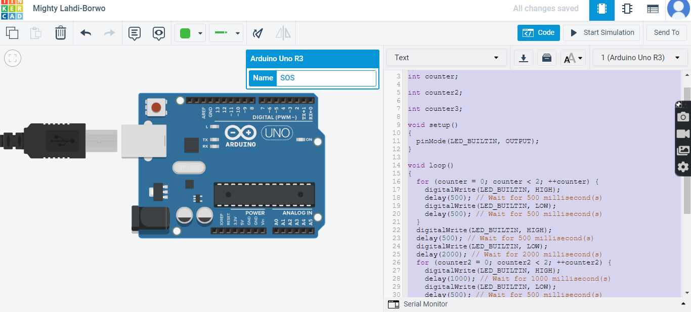
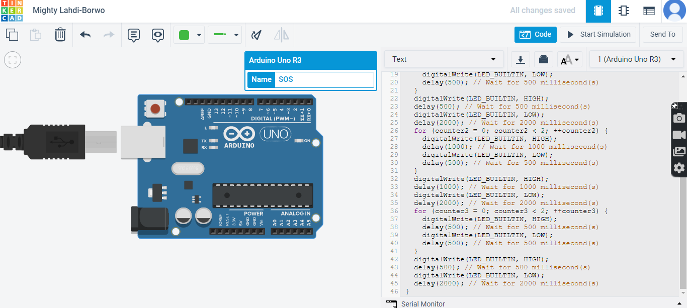
you will notice on the right is the output and the control which are the conditions to make the light blink on or off and the timing of the blink and the last picture is the text code of the program.
TinkerCAD simulation of the program: you will notice a small light yellow blinking in the middle. the softwar i used to screen record is ScreenRec
the code text of the work “SOS”:
int counter;

int counter2;

int counter3;

void setup()
{
  pinMode(LED_BUILTIN, OUTPUT);
}

void loop()
{
  for (counter = 0; counter < 2; ++counter) {
    digitalWrite(LED_BUILTIN, HIGH);
    delay(500); // Wait for 500 millisecond(s)
    digitalWrite(LED_BUILTIN, LOW);
    delay(500); // Wait for 500 millisecond(s)
  }
  digitalWrite(LED_BUILTIN, HIGH);
  delay(500); // Wait for 500 millisecond(s)
  digitalWrite(LED_BUILTIN, LOW);
  delay(2000); // Wait for 2000 millisecond(s)
  for (counter2 = 0; counter2 < 2; ++counter2) {
    digitalWrite(LED_BUILTIN, HIGH);
    delay(1000); // Wait for 1000 millisecond(s)
    digitalWrite(LED_BUILTIN, LOW);
    delay(500); // Wait for 500 millisecond(s)
  }
  digitalWrite(LED_BUILTIN, HIGH);
  delay(1000); // Wait for 1000 millisecond(s)
  digitalWrite(LED_BUILTIN, LOW);
  delay(2000); // Wait for 2000 millisecond(s)
  for (counter3 = 0; counter3 < 2; ++counter3) {
    digitalWrite(LED_BUILTIN, HIGH);
    delay(500); // Wait for 500 millisecond(s)
    digitalWrite(LED_BUILTIN, LOW);
    delay(500); // Wait for 500 millisecond(s)
  }
  digitalWrite(LED_BUILTIN, HIGH);
  delay(500); // Wait for 500 millisecond(s)
  digitalWrite(LED_BUILTIN, LOW);
  delay(2000); // Wait for 2000 millisecond(s)
}
Hero Video
Challenge
Easy Mode
program your microcontroller to blink randomly between 1 to 5.
solution:
int counter;

int counter2;

int counter3;

void setup()
{
  pinMode(LED_BUILTIN, OUTPUT);
}
void loop(){
digitalWrite(LED_BUILTIN, HIGH);
  delay (1000*random(1,5+1));
  digitalWrite(LED_BUILTIN, LOW);
  delay (1000*random(1,5+1));
}
Medium Mode
program your microcontroller to blink one word in Morse code and challenge a friend, family member, your colleagues or your instructor to figure it out.
solution: the word is “Salam”. Due to the code being a little bit long i used TinkerCAD to make it faster and then i copied the code to Arduino to program my microcontroller.
// C++ code
//
int counter;

void setup()
{
  pinMode(LED_BUILTIN, OUTPUT);
}

void loop()
{
  for (counter = 0; counter < 2; ++counter) {
    digitalWrite(LED_BUILTIN, HIGH);
    delay(500); // Wait for 500 millisecond(s)
    digitalWrite(LED_BUILTIN, LOW);
    delay(500); // Wait for 500 millisecond(s)
  }
  digitalWrite(LED_BUILTIN, HIGH);
  delay(500); // Wait for 500 millisecond(s)
  digitalWrite(LED_BUILTIN, LOW);
  delay(2000); // Wait for 2000 millisecond(s)
  digitalWrite(LED_BUILTIN, HIGH);
  delay(500); // Wait for 500 millisecond(s)
  digitalWrite(LED_BUILTIN, LOW);
  delay(500); // Wait for 500 millisecond(s)
  digitalWrite(LED_BUILTIN, HIGH);
  delay(1000); // Wait for 1000 millisecond(s)
  digitalWrite(LED_BUILTIN, LOW);
  delay(2000); // Wait for 2000 millisecond(s)
  digitalWrite(LED_BUILTIN, HIGH);
  delay(500); // Wait for 500 millisecond(s)
  digitalWrite(LED_BUILTIN, LOW);
  delay(500); // Wait for 500 millisecond(s)
  digitalWrite(LED_BUILTIN, HIGH);
  delay(1000); // Wait for 1000 millisecond(s)
  digitalWrite(LED_BUILTIN, LOW);
  delay(500); // Wait for 500 millisecond(s)
  digitalWrite(LED_BUILTIN, HIGH);
  delay(500); // Wait for 500 millisecond(s)
  digitalWrite(LED_BUILTIN, LOW);
  delay(500); // Wait for 500 millisecond(s)
  digitalWrite(LED_BUILTIN, HIGH);
  delay(500); // Wait for 500 millisecond(s)
  digitalWrite(LED_BUILTIN, LOW);
  delay(2000); // Wait for 2000 millisecond(s)
  digitalWrite(LED_BUILTIN, HIGH);
  delay(500); // Wait for 500 millisecond(s)
  digitalWrite(LED_BUILTIN, LOW);
  delay(500); // Wait for 500 millisecond(s)
  digitalWrite(LED_BUILTIN, HIGH);
  delay(1000); // Wait for 1000 millisecond(s)
  digitalWrite(LED_BUILTIN, LOW);
  delay(2000); // Wait for 2000 millisecond(s)
  digitalWrite(LED_BUILTIN, HIGH);
  delay(1000); // Wait for 1000 millisecond(s)
  digitalWrite(LED_BUILTIN, LOW);
  delay(500); // Wait for 500 millisecond(s)
  digitalWrite(LED_BUILTIN, HIGH);
  delay(1000); // Wait for 1000 millisecond(s)
  digitalWrite(LED_BUILTIN, LOW);
  delay(2000); // Wait for 2000 millisecond(s)
}
Python
Python is originally a coding language that big companies use now days but it also have circuit programing sittings that can be downloaded through the steps below:
Firstly install via this link: python and this will show on your screen.
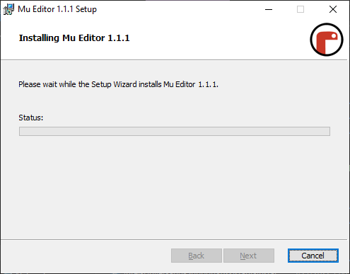
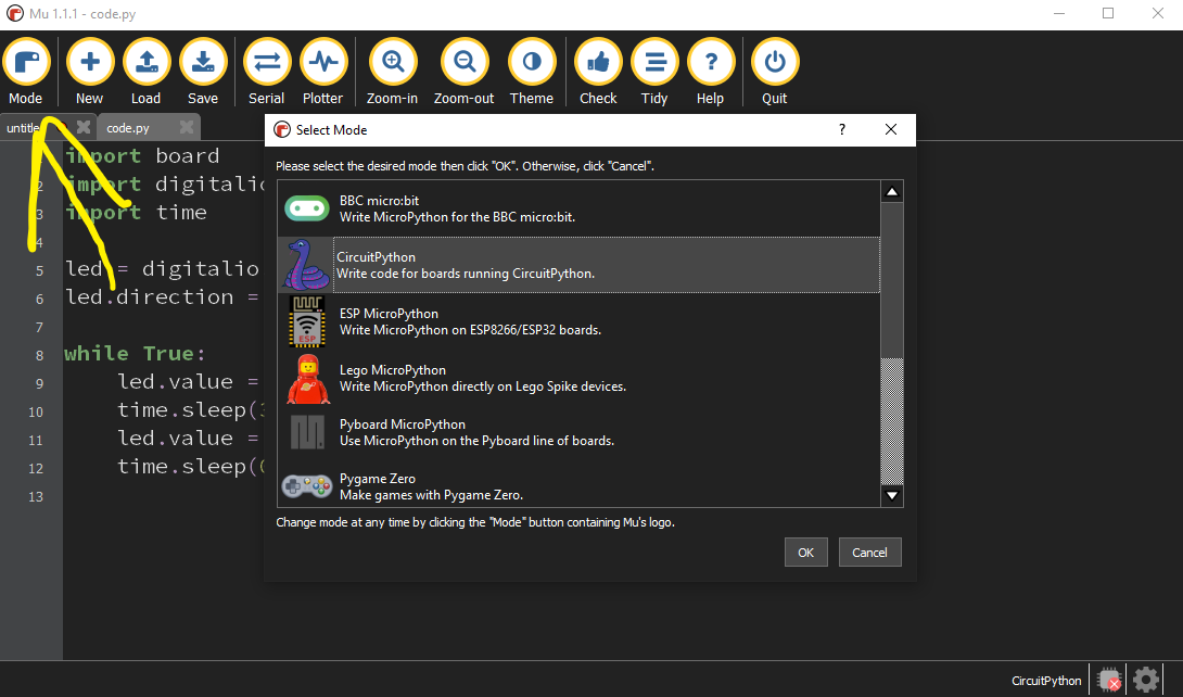
Secondly, then launch the software and choose the correct mode for Python.

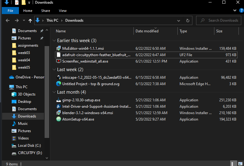
Thirdly, download the files of your microcontroller with the same name via this link: Circuit Python
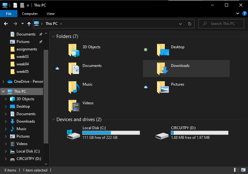
Fourthly: connect your microcontroller and then drag the downloaded files (from THIRD step) and drop them inside your microcontroller which will appear in MY PC.
Finally, follow the instructions on this link and try the code on the same website to test if the microcontroller is connected to Python. the code i tested is below:
import board
import digitalio
import time

led = digitalio.DigitalInOut(board.LED)
led.direction = digitalio.Direction.OUTPUT

while True:
    led.value = True
    time.sleep(3.0)
    led.value = False
    time.sleep(0.5)