7. Input & Output device
This week we learnt about Input and output devices in theory. In addition, we learnt about how to connect them to a microcontroller board and how to programme them. We also acquired the ability of solving the problems we might face while programming.
Input vs. Output
- Input devices: A piece of equipment/hardware which helps us enter data into a computer is called an input device. For example keyboard, mouse, etc.

- Output devices: A piece of equipment/hardware which gives out the result of the entered input, once it is processed (i.e. converts data from machine language to a human-understandable language), is called an output device. For example printer, monitor, etc.
Analog vs. Digital Signals
- Analog signal: Signals which are Continuous as time varying in nature
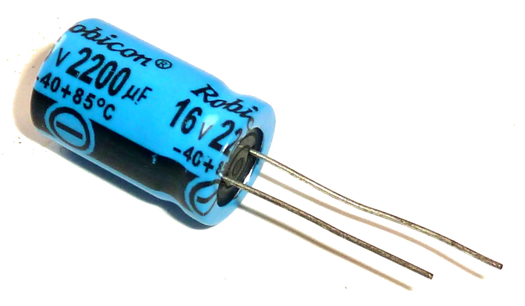
Components like resistors, Capacitors, Inductors, Diodes are used in analog circuits.
- Digital signal: Signals which are discrete
Components like transistors, logic gates, and micro-controllers are used in Digital circuits.
![]()
Input (Line Tracking Sensor)
Information
I looked for the basic function of the sensor and here is what I found: “KY-033 Line tracking sensor– A line tracking sensor and it does exactly what the name suggests it tracks black lines against white background or white lines against black background”
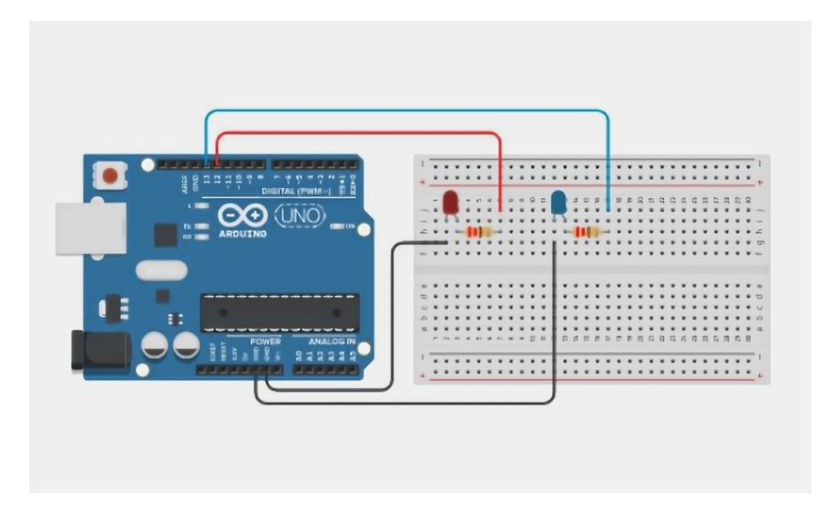
Then, I looked for the connection method -connecting the sensor to the board- and I found this photo useful:

Note: Even if the boards are different the pins are almost the same.
Programming
Here is the code I used to programme the sensor.
#include <SoftwareSerial.h>


void setup()
{
Serial.begin(9600); // activates Serial Communication
}

void loop()
{
Serial.println(analogRead(A0)); // Line Tracking sensor is connected with pin 5 of the Arduino
delay(500);
}
Problems
- Problem 1
For the line tracking sensor, the digital analog should be used and that’s what I did at first. However, when I opened the serial monitor the readings were all zero despite putting the sensor against a black surface as you can see:
Then, the instructor suggested to try digital analog. The sensor worked and readings were shown.
Hero video
Here is the video of the sensor at work:
Here are the values it is showing:
when I put the sensor against a white surface a low number appear on the screen. On the other hand, if I remove this surface a high number appears.
Output (2-colour LED)
Information
When I searched for the LED, I had a hard time identifying which type of LED is this. I tried searching for the name written on the output itself but I didn’t find a matching results. Finally, I found a website that listed 37 Arduino devices and my LED was among them. This is was I found from this website: “This LED contains two light emitting diodes. One pin is the GND and the other two are for a red and green LED.”
As for the connection, I didn’t have a picture showing me how to connect the wires but there were the name of the pins I had to connect to. Since I figured out what the pins’ names mean from previous sessions I was able to connect the 2-colour LED after a few trials and errors :)
Programming
Here is the code I used to program the LED.
int redpin = 11; // select the pin for the red LED
int greenpin = 10; // select the pin for the green LED
int val;
void setup () {
   pinMode (redpin, OUTPUT);
   pinMode (greenpin, OUTPUT);
}
void loop () {
   for (val = 255; val> 0; val--)
      {
      analogWrite (greenpin, val);
      analogWrite (redpin, 255-val);
      delay (15);
   }
   for (val = 0; val <255; val++)
      {
      analogWrite (greenpin, val);
      analogWrite (redpin, 255-val);
      delay (15);
   }
}
Problems
- Problem 2
First, I had a problem connecting the Two-colour LED to the board but with the help of an instructor I was able to know the meaning of the letters on the LED and therefore connect them to the board.
- problem 3
The code I used was not working. I tried compiling it several times and I did some debugging but it was still not working. At the end, I found out that the code was not for a two-colour LED :-)
Hero video
Here is the 2-colour LED at work:
References
- Input vs. Output
- Light Tracking Sensor
- Source Code (input)
- Source code (Output)
- Analog vs. Digital signals