3. Computer controlled cutting
This week we learnt about the Laser cutting machine which is a type of automatic laser system with CNC controller, which adopts CO2 or FIBER laser beam to cut different materials.
Group Assignment
Part 1
The first part of the assignment can be found on my colleague’s website: sakeena.almansoor
Part 2
Kerf
- What is Kerf?
When a laser cuts through a piece of material, the laser’s own width displaces a little extra material than is specified in the original design. The amount of material that is burned away is known as the kerf in laser cutting.
- Kerf Test
First, we searched for the best method to test the kerf. Then, we settled on cutting a square of known size, which was 4 x 4 cm, then measure the kerf.
- How do you measure the kerf?
The original width of the square is 4.0 cm. After cutting the square using the laser cutting machine we measured the square using an electronic calliper
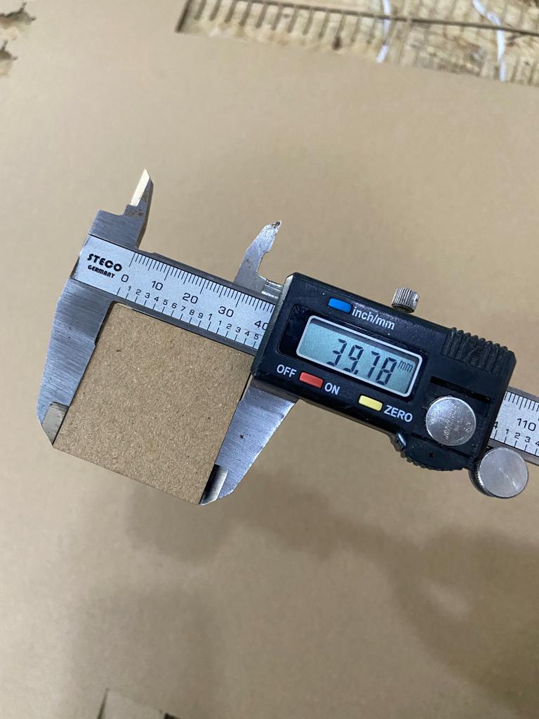
As seen from the photo, the measured width is 39.78mm. To find the kerf, we subtract this number from 40.00mm and divide the answer by 2:
40.00mm-39.78mm= 0.22mm 0.22/2= 0.11mm
Therefore, the kerf is 0.11mm
Joint Clearance
- Types of joints
Finger joints, mortise and tenon joints, and slotting joints are the most commonly used with laser cut structures, because they’re very simple and sturdy.
We are most likely going to work with the finger joints.
- Joints Test
To know the suitable width of the finger joint while accounting for the kerf we had to do the joint Test.
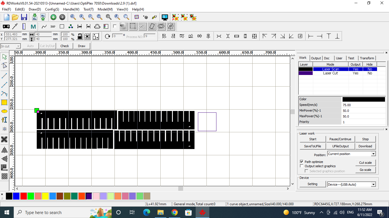
First, we opened the design on the computer linked to the machine
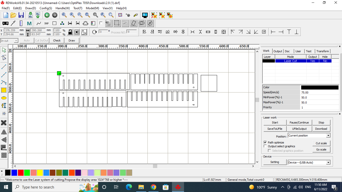
Then we modified the settings to the optimum speed and the power according to our previous findings (refer to part 1 of the assignment) :
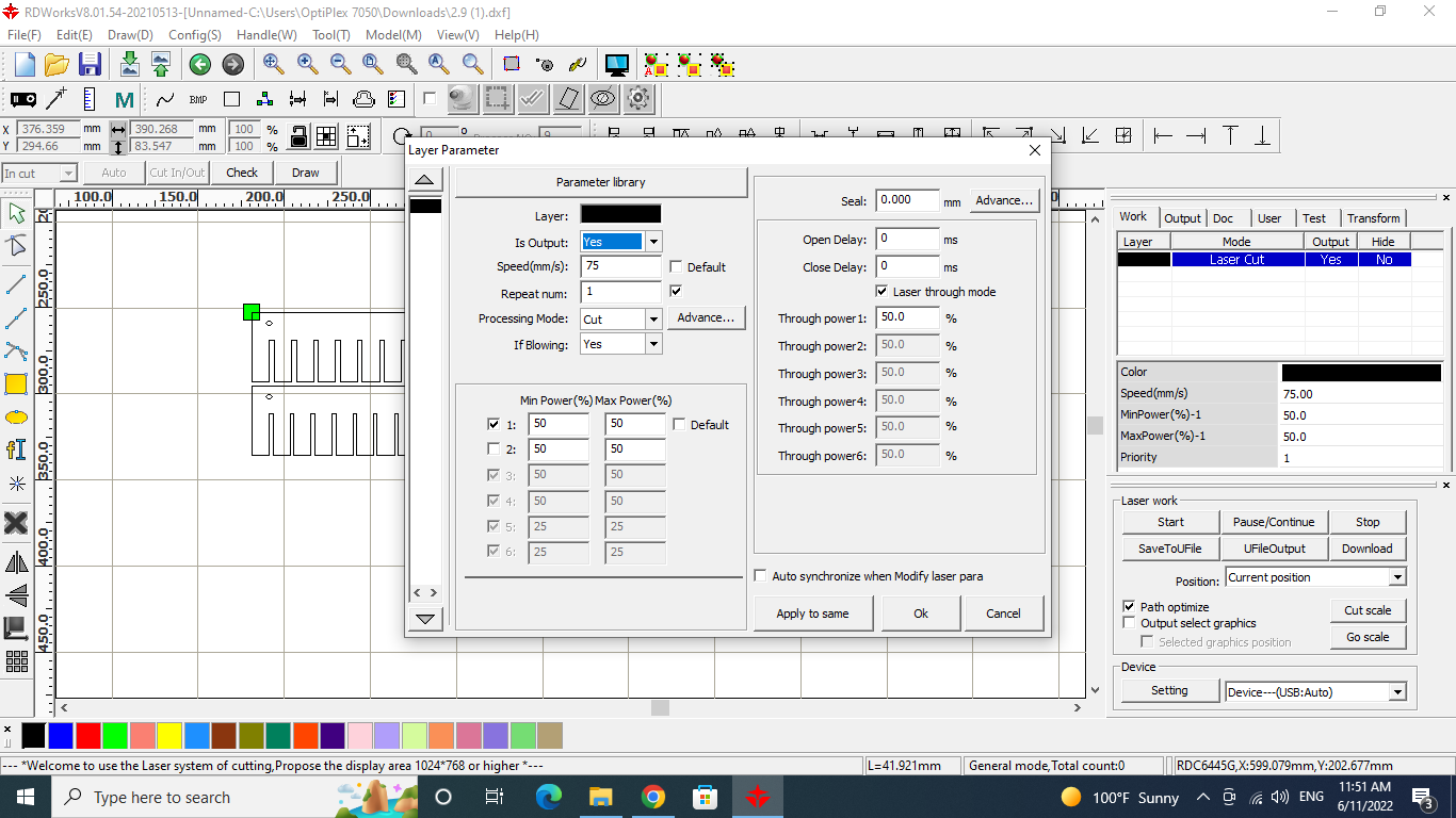
We also colour-coded the settings to black:
After downloading the design and cutting it by the machine, we marked the width of each slit -in mm- as seen:
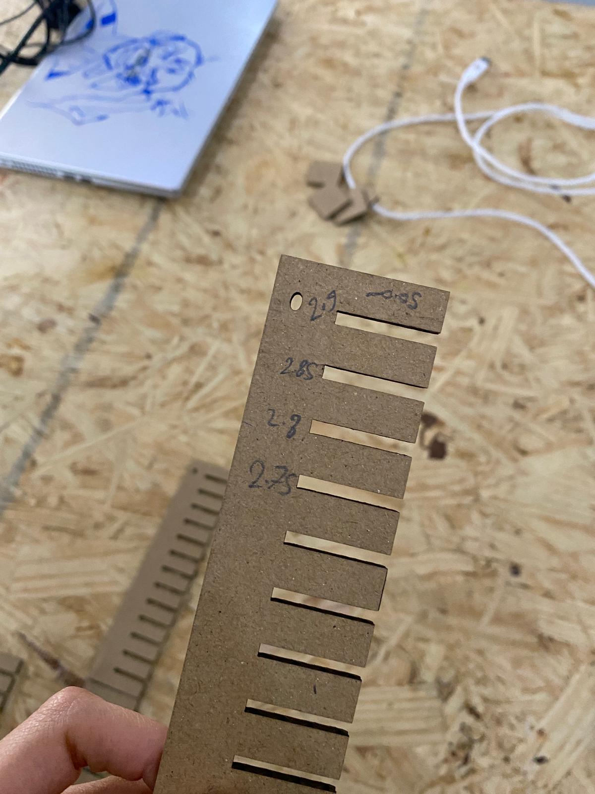
Then, we tried joining the material with the different slits:
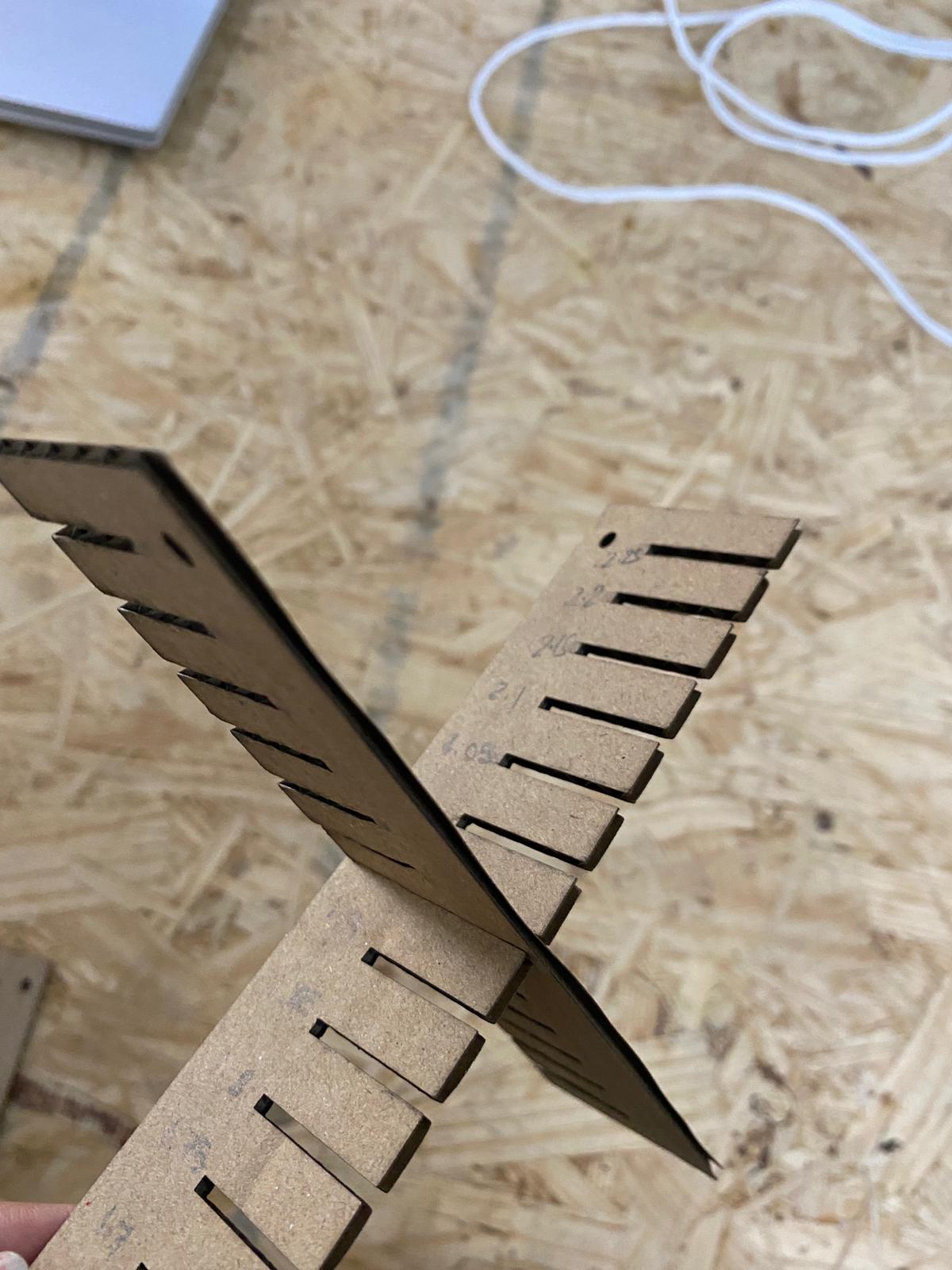
At the end, we found the best width to be 2.2mm since: - The smaller widths would be too tight - The bigger widths would cause the pieces to be loose.
Individual Assignment
Laser Cutting Machine
Design
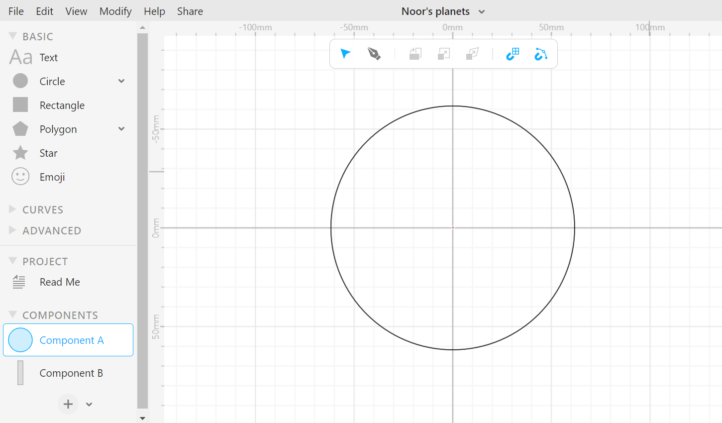
To design my parametric press-fit construction kit I used cuttle.xyz
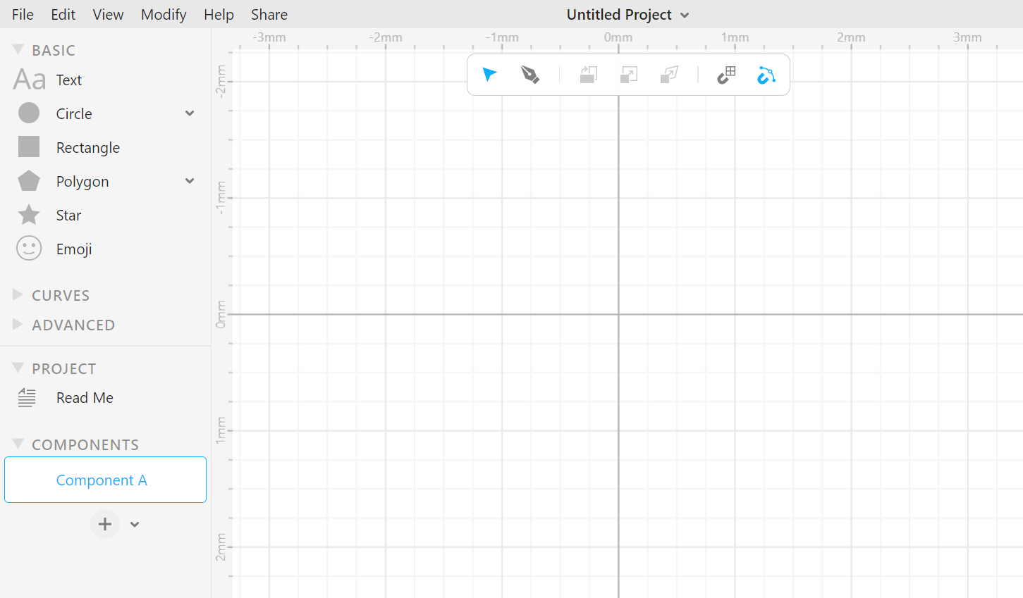
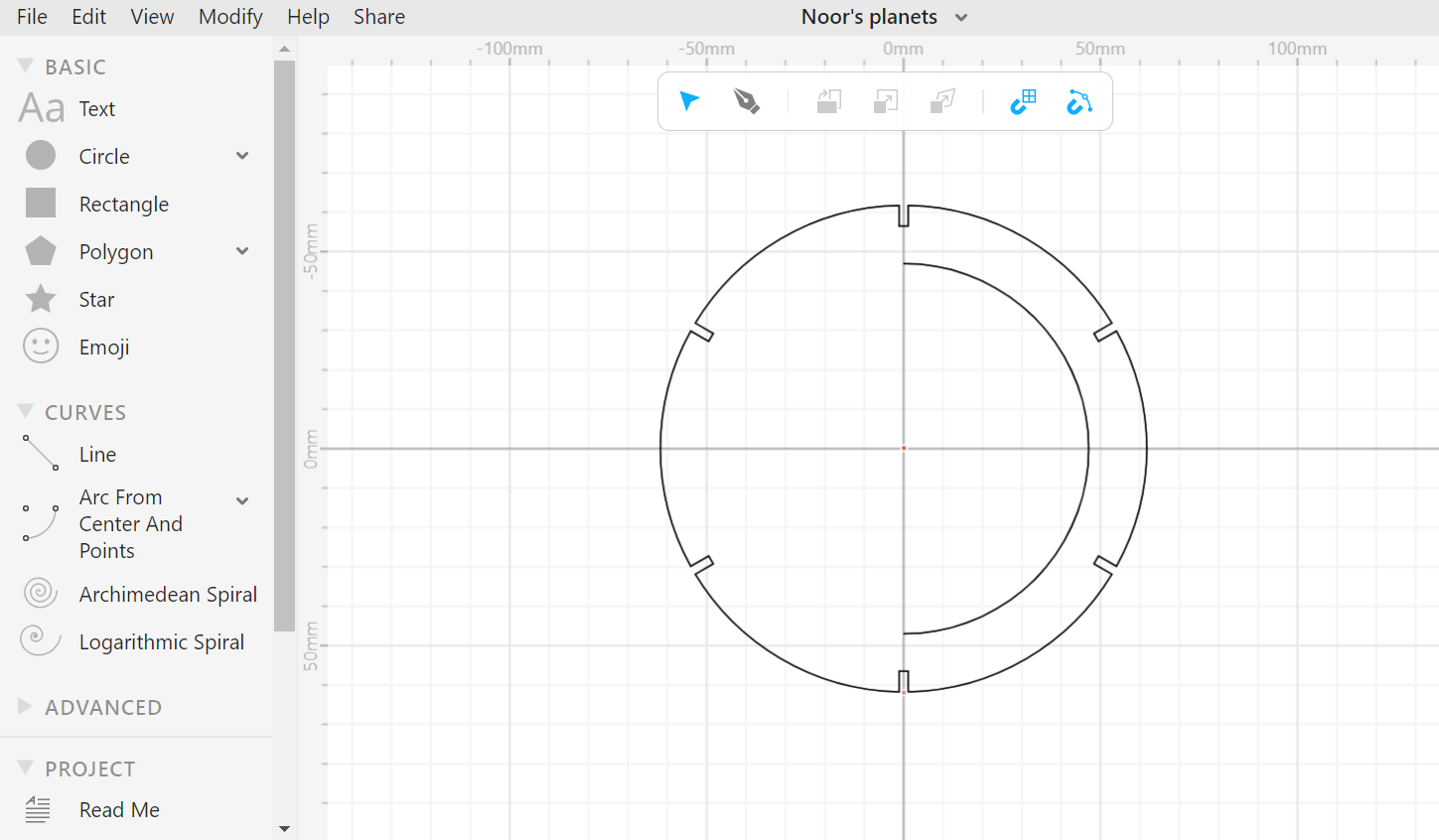
First, I created a circle
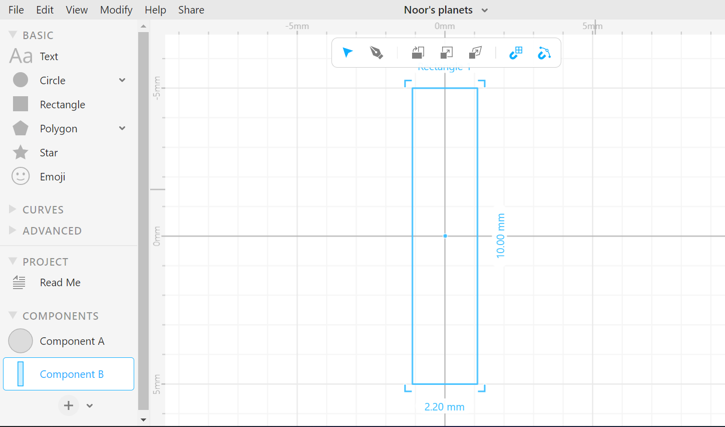
Second, I created a rectangle as a second component and I took the 2.2mm width into consideration
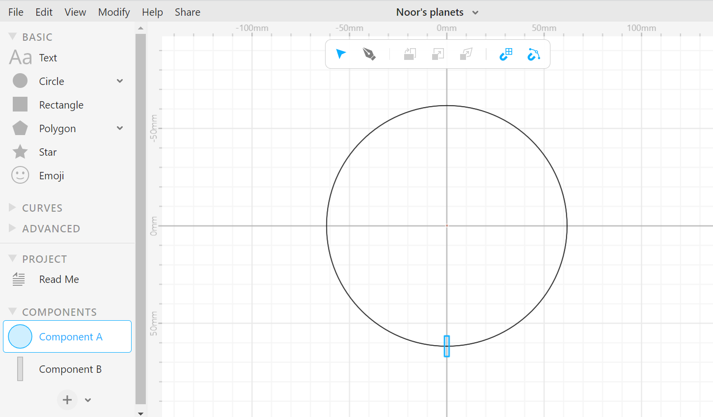
I dragged the rectangle to the circle
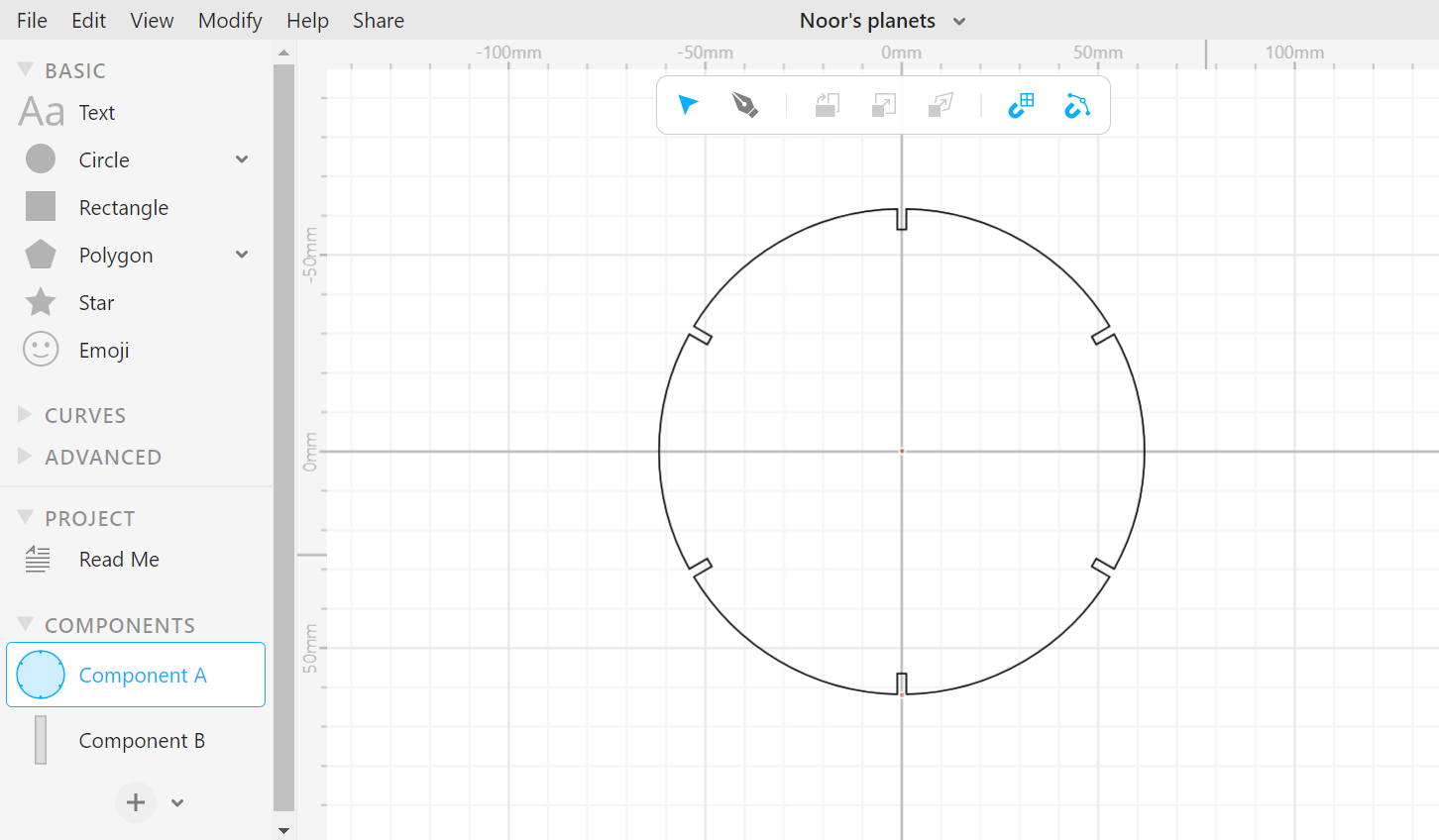
I created multiple rectangles my rotational repeat and modified them using Boolean difference tool
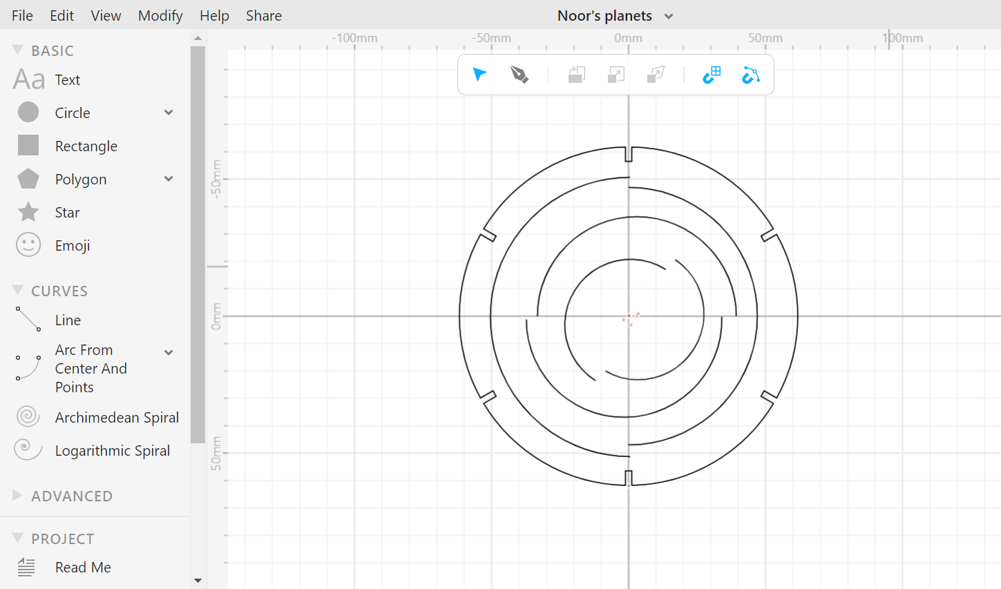
I added half a circle in the original circle
I added a few more to be the rings of the planet when folded later
Finally, I added a few pentagons and used the Boolean difference tool for aesthetic :)
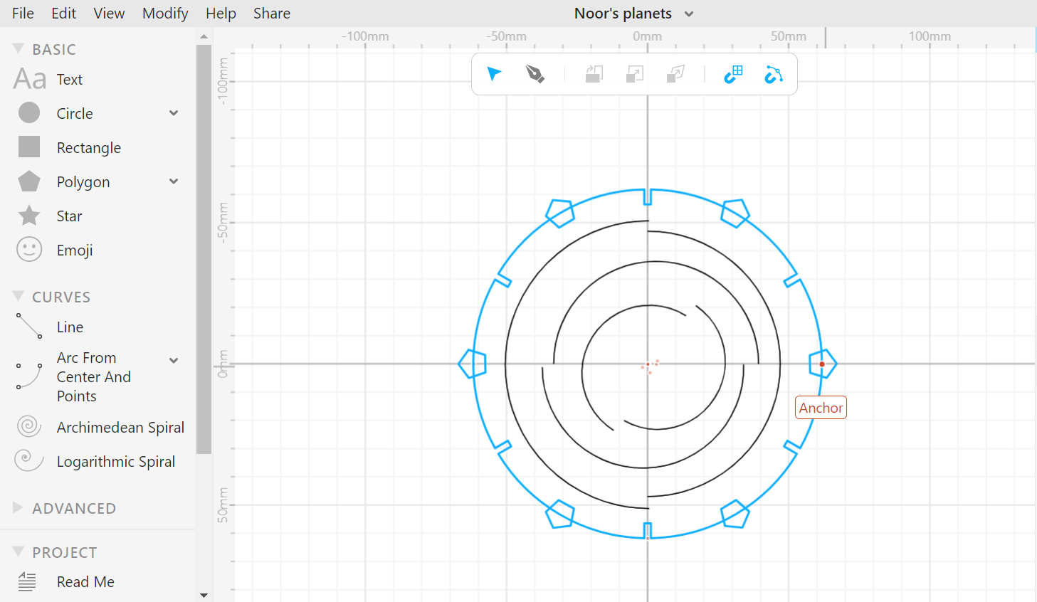
You can download the design here
Note: I have not come up with the design entirely on my own, refer to the references.
Cutting and assembling
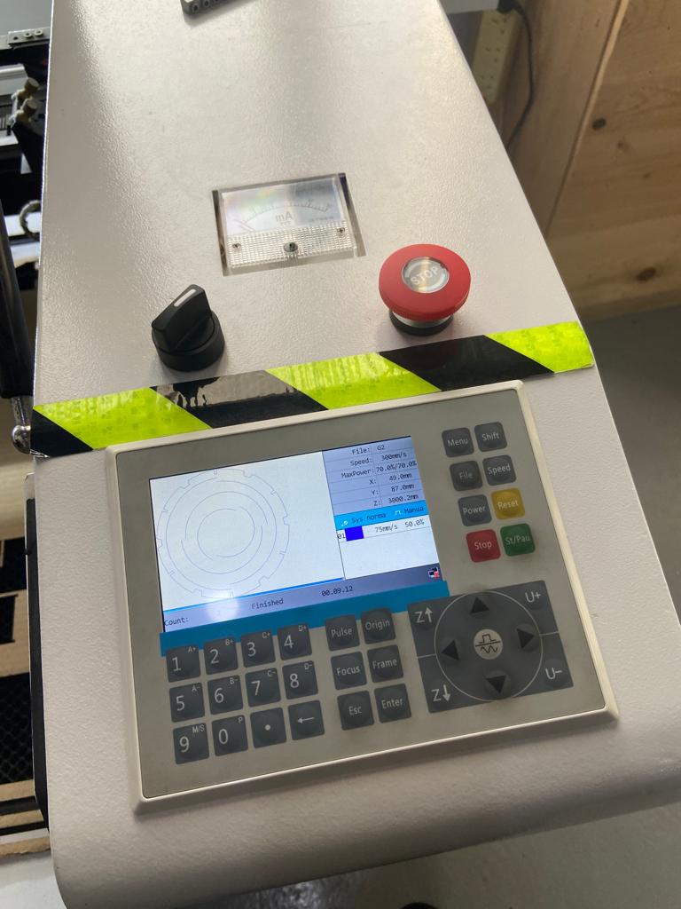
The first step is to import the design on the linked laptop
Then, changing the speed and power according to the findings of the Group Assignment
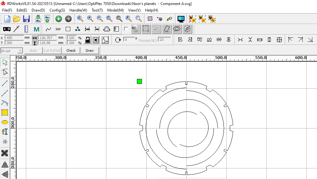
Downloading it to the laser cutting machine
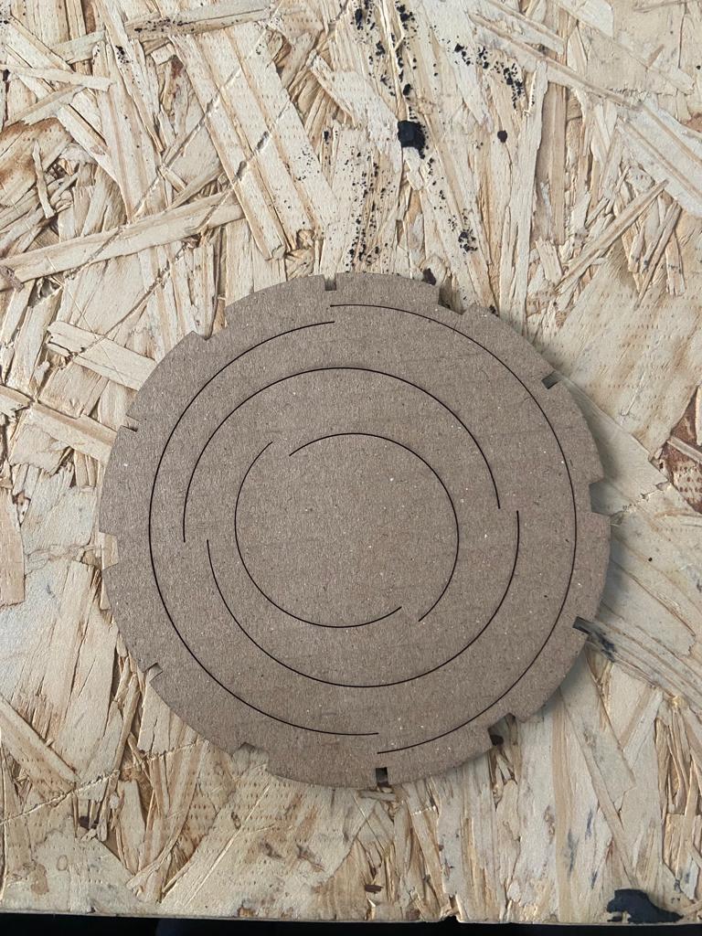
After cutting my design on the laser cutting machine, it came out like this:
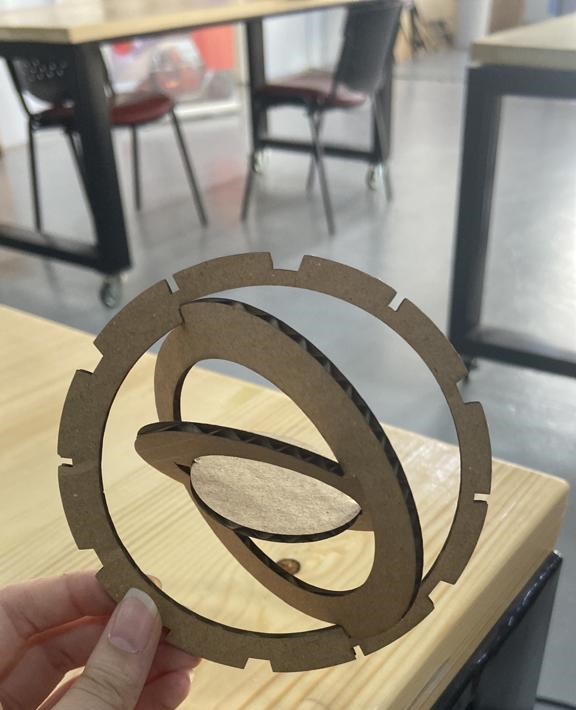
This is how the final design looks after folding the rings:
Vinyl cutter
Design
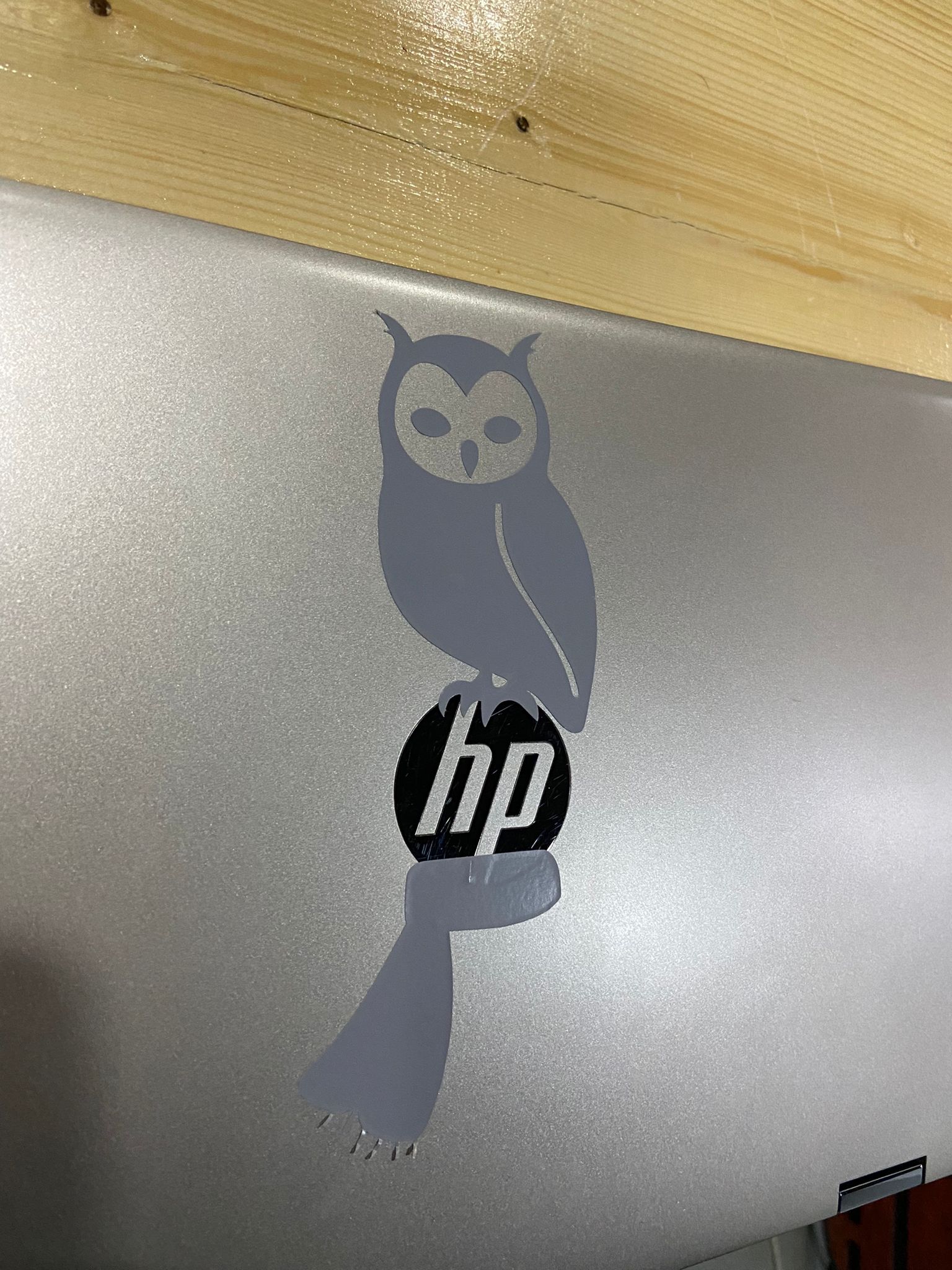
First, I looked for a design for my laptop and I wanted to utilise the hp logo so I searched for a design that is related to Harry Potter.
I chose the following 2 pictures to make stickers of:

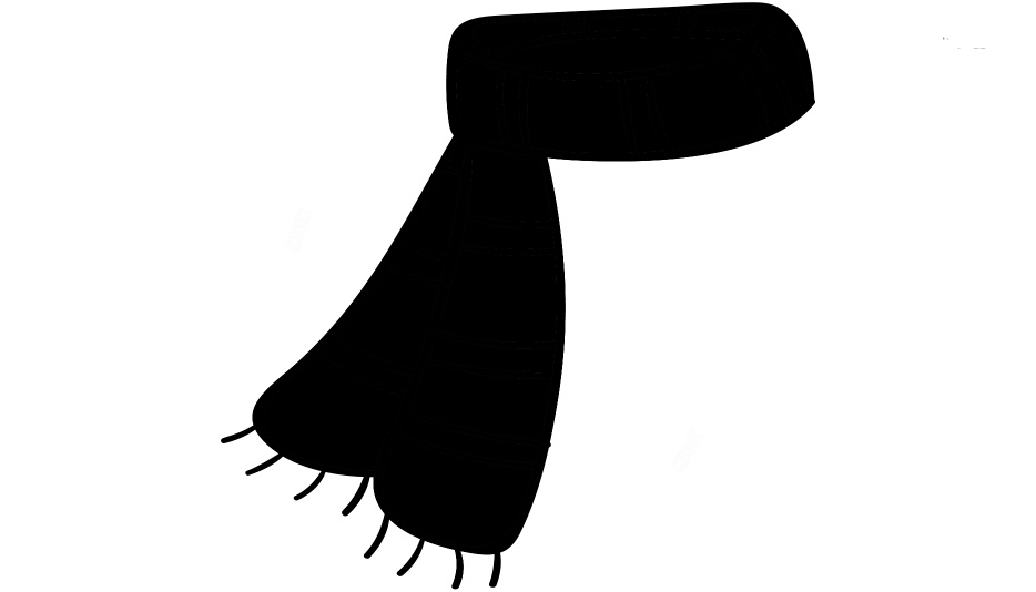
Original pictures: - scarf - owl
I converted the format of the pictures from png to dxf through inkscape before sending them to the machine.
Here are the Scarf DXF file and the Owl DXF file
Cutting and Final Result
A piece of the chosen material was cut and taped on the platform.
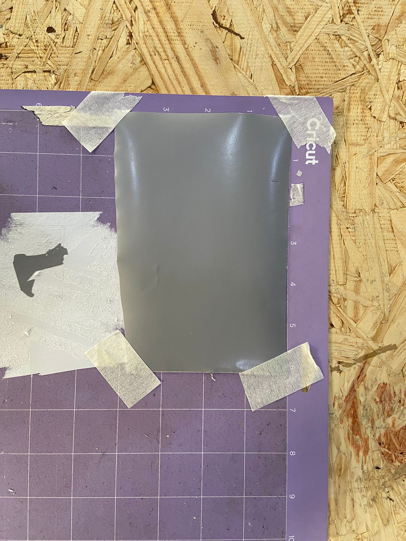
Then the machine started cutting the owl and the scarf. We repeated the process twice to ensure that the stickers are cut.
Then, I removed the excess material and separated the 2 stickers by scissors to be able to put them easily on the laptop.
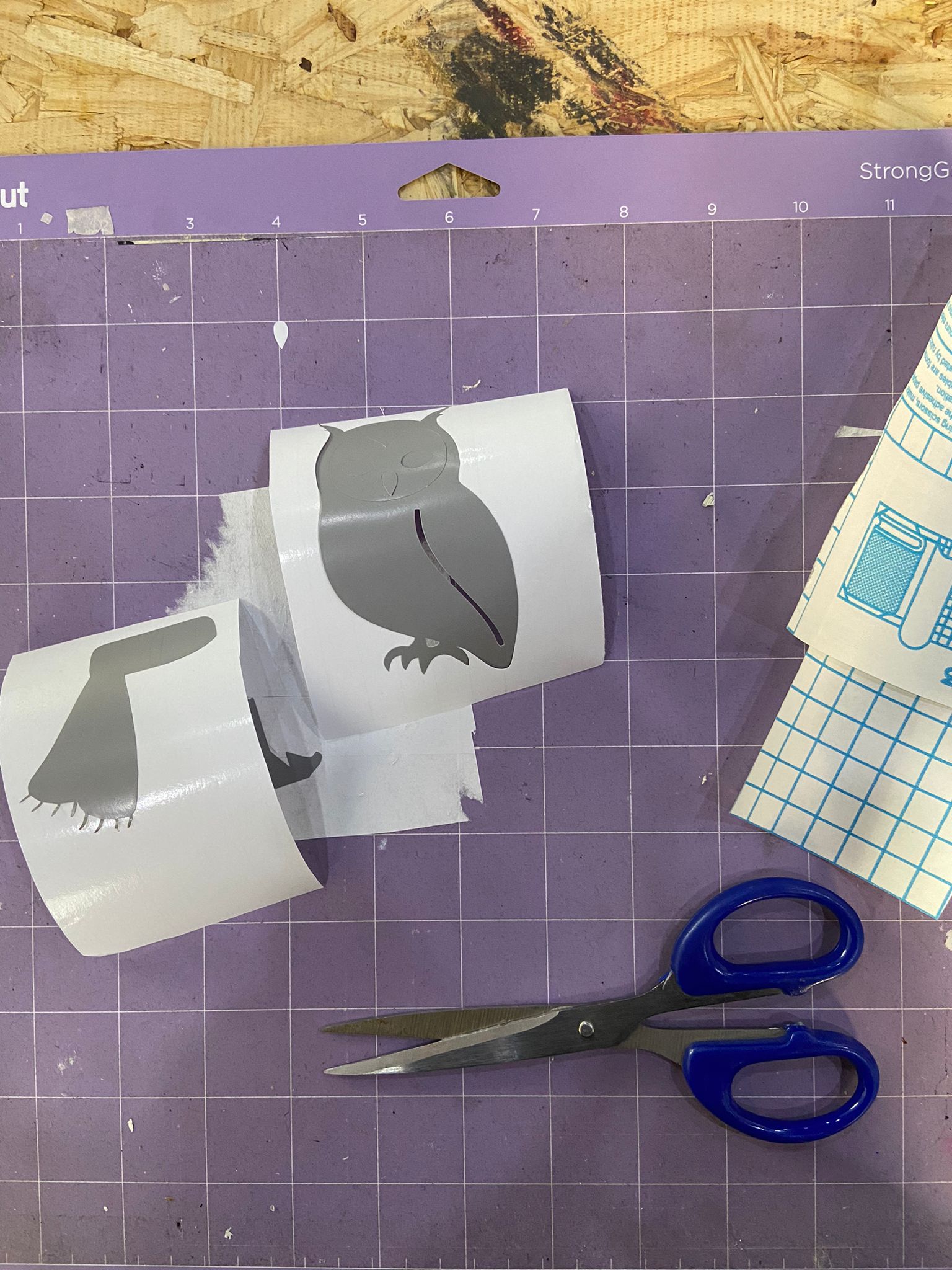
This is the final result!