6. Large format CNC (computer controlled Machining)
This week we learnt about the computer controlled machining. We learnt about Drill bits, RPM, Feed rate and joints. We also made our own designs to be cut with the CNC machine.
Theory
What is CNC?
The term CNC stands for ‘computer numerical control’, and the CNC machining definition is that it is a subtractive manufacturing process that typically employs computerized controls and machine tools to remove layers of material and produces a custom-designed part.
Drill bits
There are different types of drill bits that produces different cut shapes
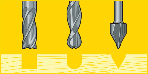
- End mill
- Ball end mill
- Straight end mill
- V-carve bit
RPM and Feed Rate
Feed Rate
It is one of the most important factors to consider when implementing any CNC strategy. Simply put, feed rate is the speed at which the cutter engages the part and is typically measured in units/minute.
RPM
It is the rotational speed of the cutter or workpiece. Speed is the recommended cutting speed of the material in meters/minute or feet/min. Diameter in millimetres or inches.
Joints
There are many types of joints and the following picture, which was provided by the instructors, demonstrates some:
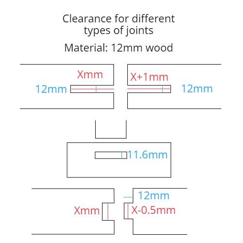
The joints in the picture are: - Finger joint? - Mortise and Tenon - Comb joint
The picture also provides the sizes of joints according to their type. As seen, the hole has to be smaller so that the plywood get stuck inside without being loose.
Note: The sizes above works for 12mm plywood
Vcarve
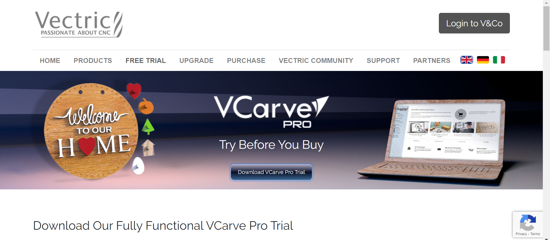
Then we were asked to download Vcarve which is a powerful software for creating and cutting parts on a CNC Router. The pro version of the software enables you to produce complex 2D patterns with profile, pocket and inlay toolpaths, plus gives you the ability to create designs with v-carving textures and much more.
We downloaded Vcarve Pro Trial Edition from their website
We learnt about different toolpaths, fillets, passes and tabs which you will see on the software later in the individual assignment.
Group Assignment
For the group assignment we tried the shopbot machine to test for runout, alignment, speeds, feeds, and toolpaths.
Individual Assignment
Choosing an Idea and Designing
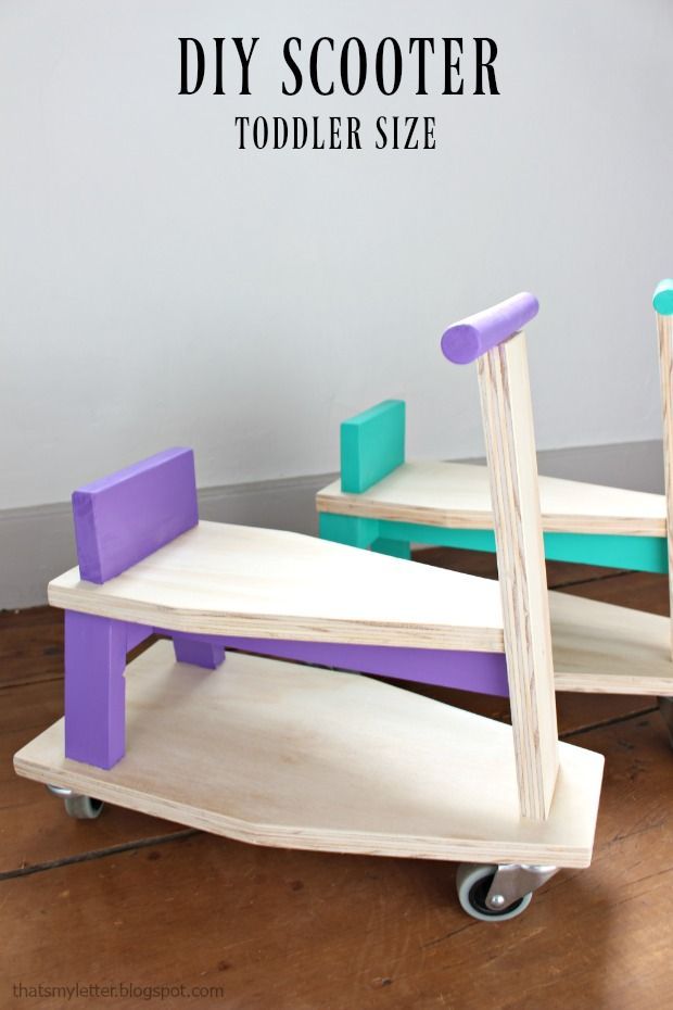
We were told to create a design to give to a kids charity. We were also given a Pinterest board full of ideas to choose from. After some thought I chose to make a scooter.
This is the picture I found from Pinterest
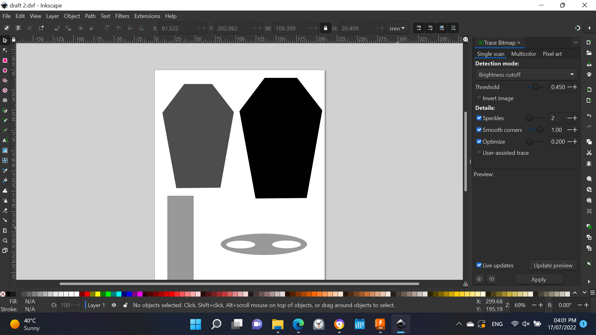
Then I started by figuring out the separate parts I have to design. For this draft I used Inkscape.
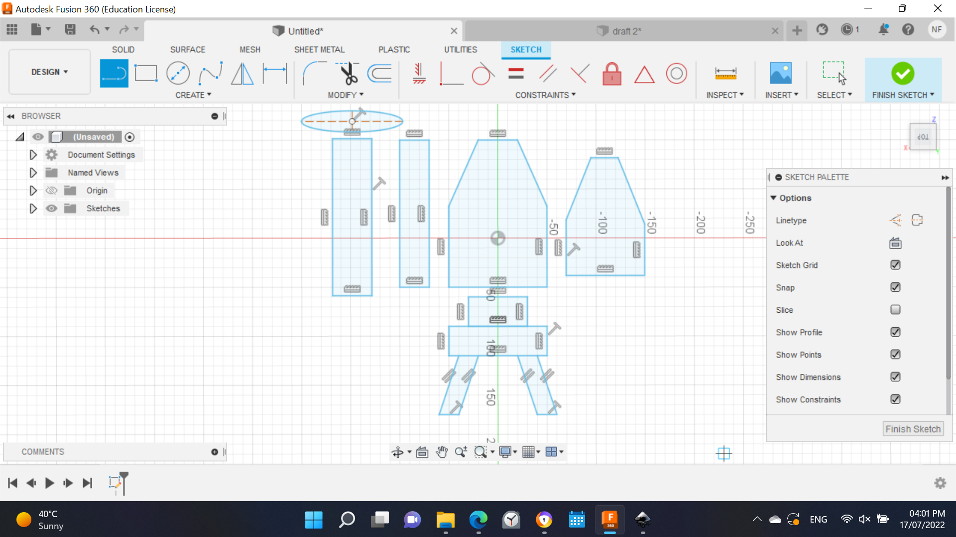
I did not really like the parts nor liked using inkscape so I made new parts on Fusion 360
I struggled a bit with the dimensions but I figured them out after trying multiple methods to get them right (One of the methods is using my little brother’s bike and measuring its dimensions)
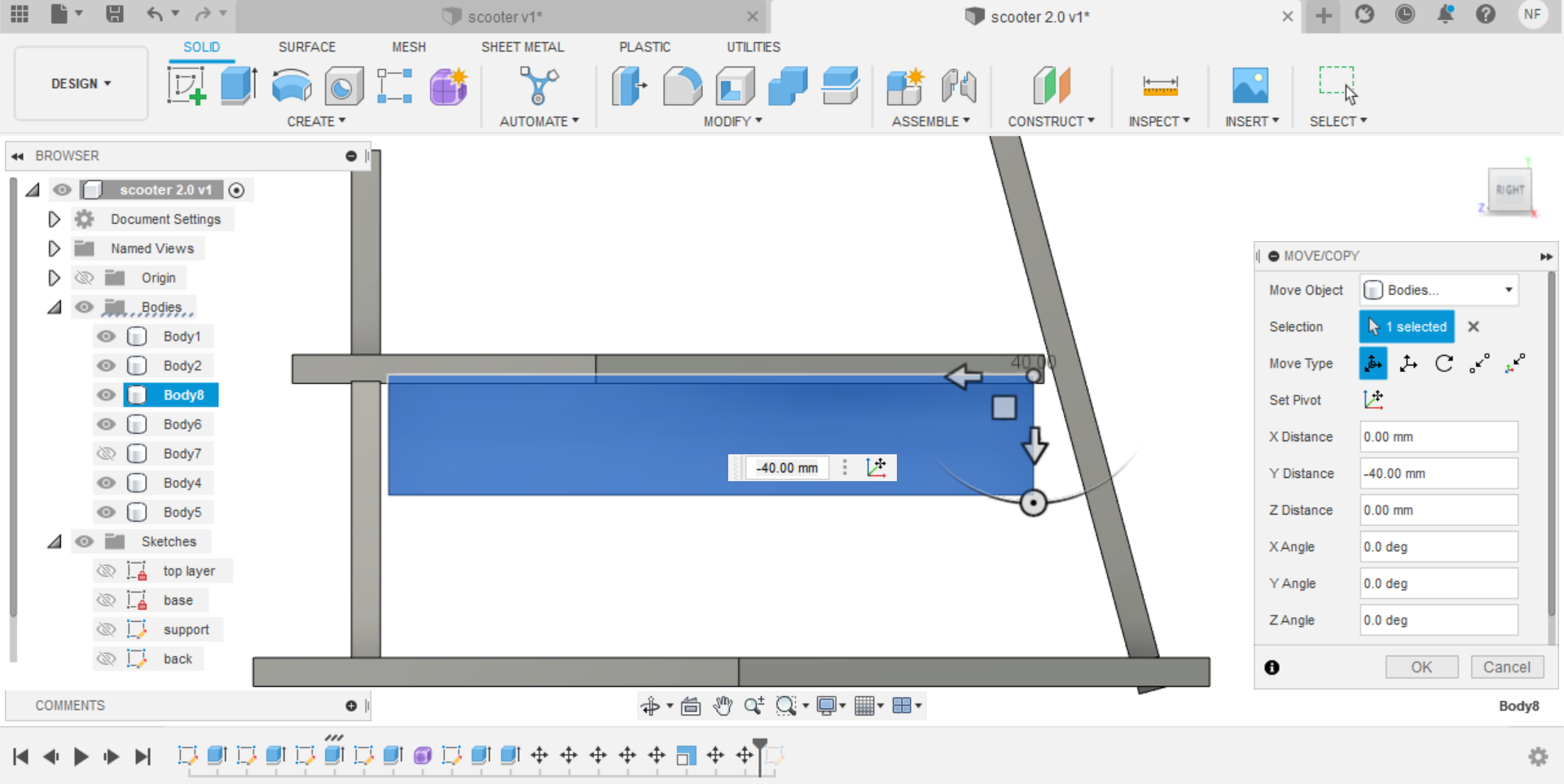
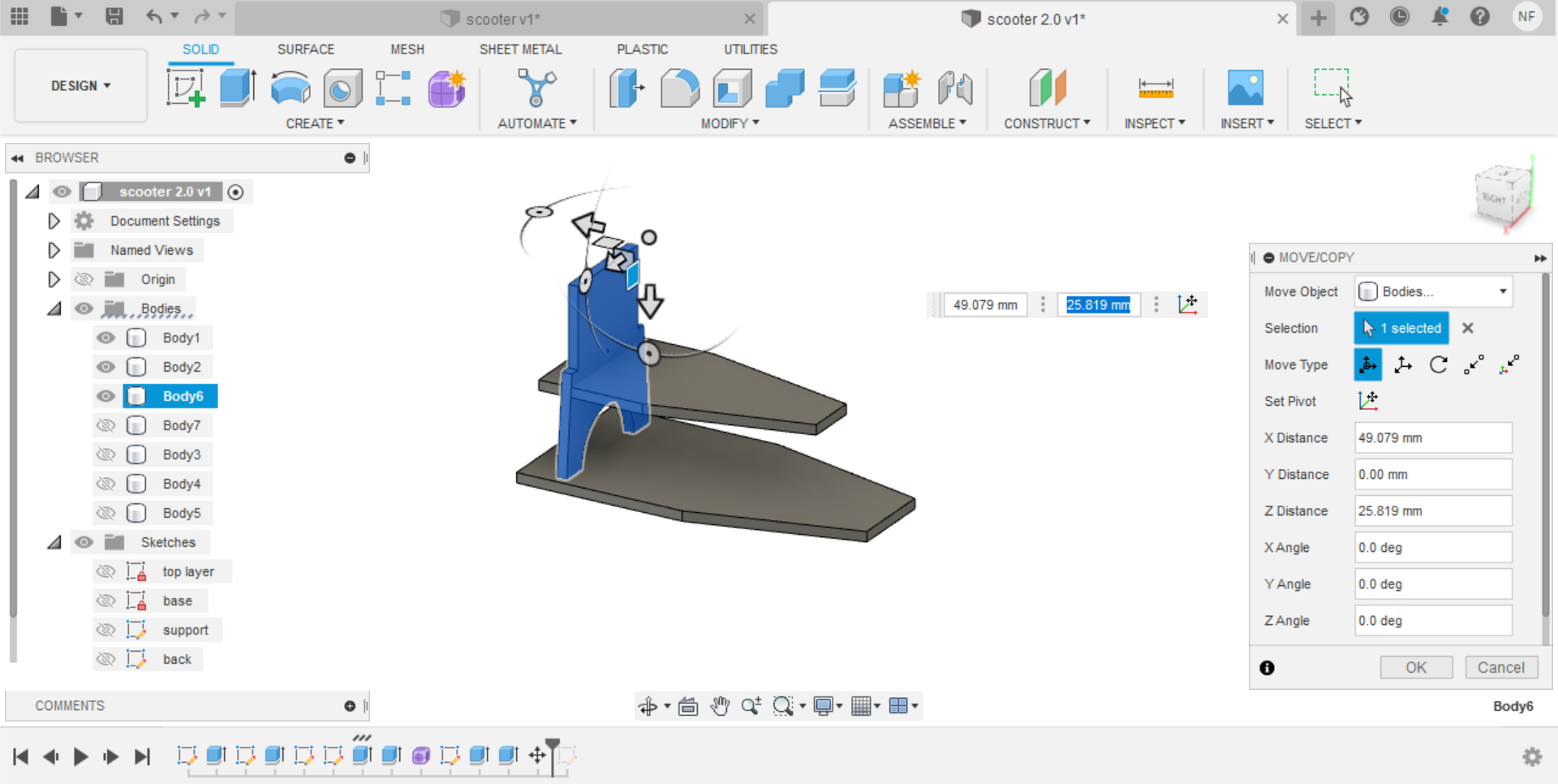
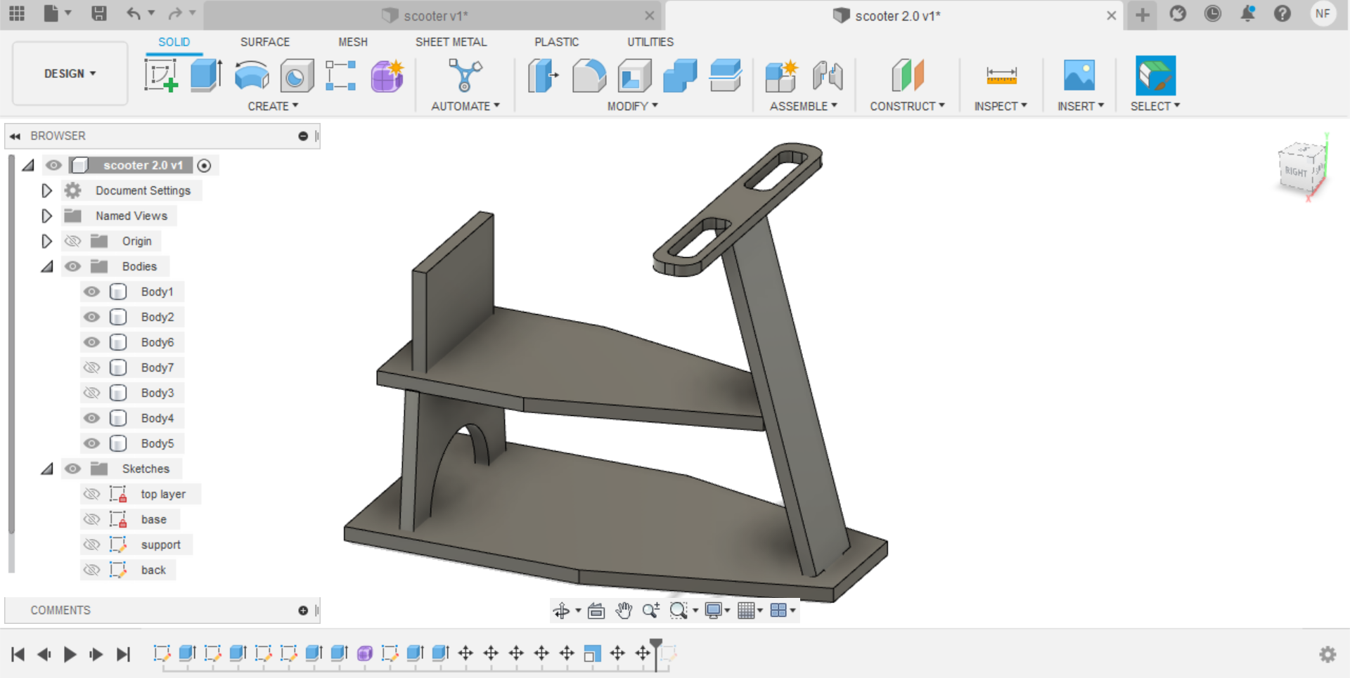
After I was happy with the sketches I made I extruded the parts and tried to assemble them using the “Move tool” to see how they look together.
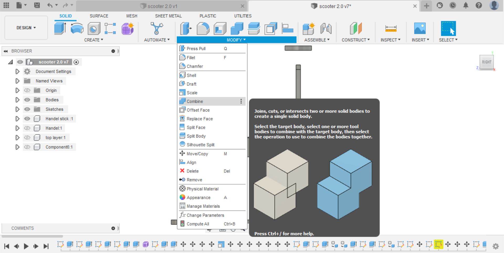
The last step in the design was to create the joints. For my design I needed only mortise and tenon joints. This is the step that was the most time consuming for me. I watched a couple of tutorials on how to make joints but still I couldn’t make proper joints and my method was just too long. It took the help of two instructors and two powerful tools to finalize my design.
Combine tool, which created the holes in the needed parts
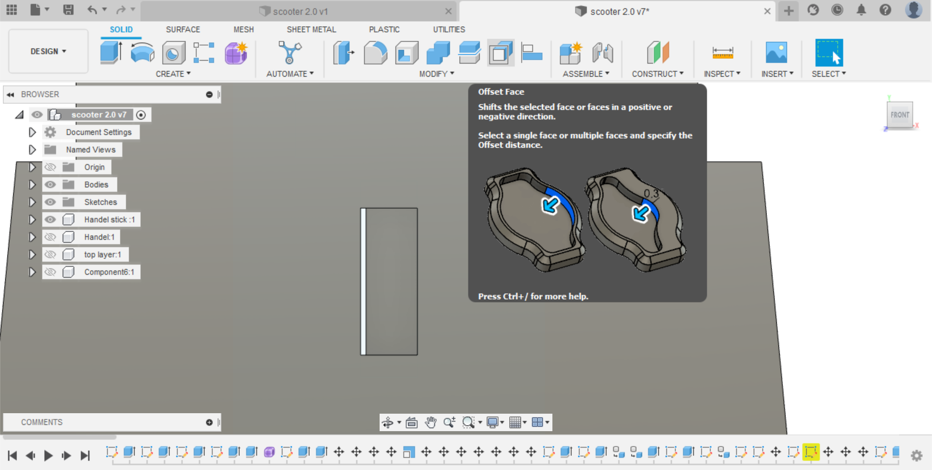
Offset tool, since we need the hole to be 11.6mm wide which is less than the thickness of the plywood
After aligning every part with the align tool, this is the final design!
I am sorry about the view but you can always rotate the scooter :)
You can download the design here
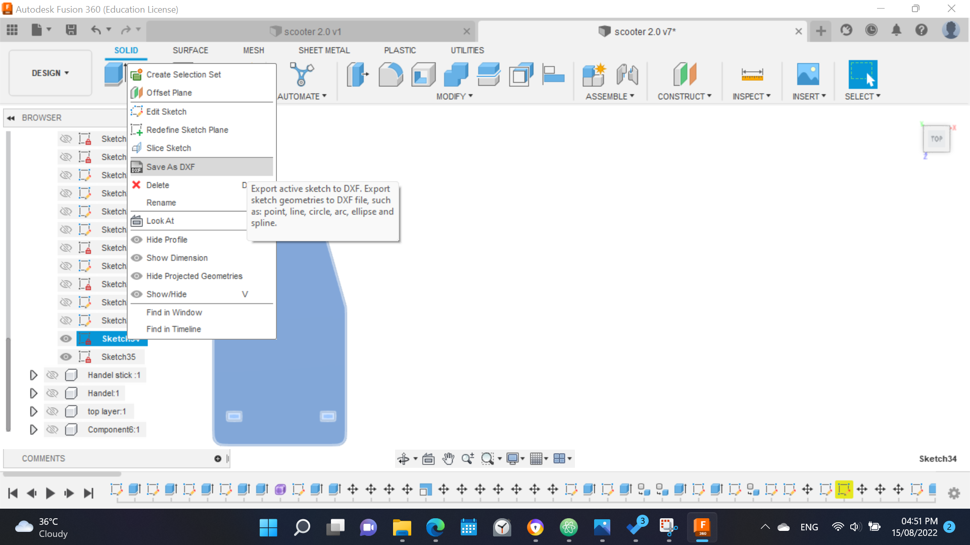
Before sending the design to the machine I had to save each piece as DXF file.
CNC machine and Vcarve
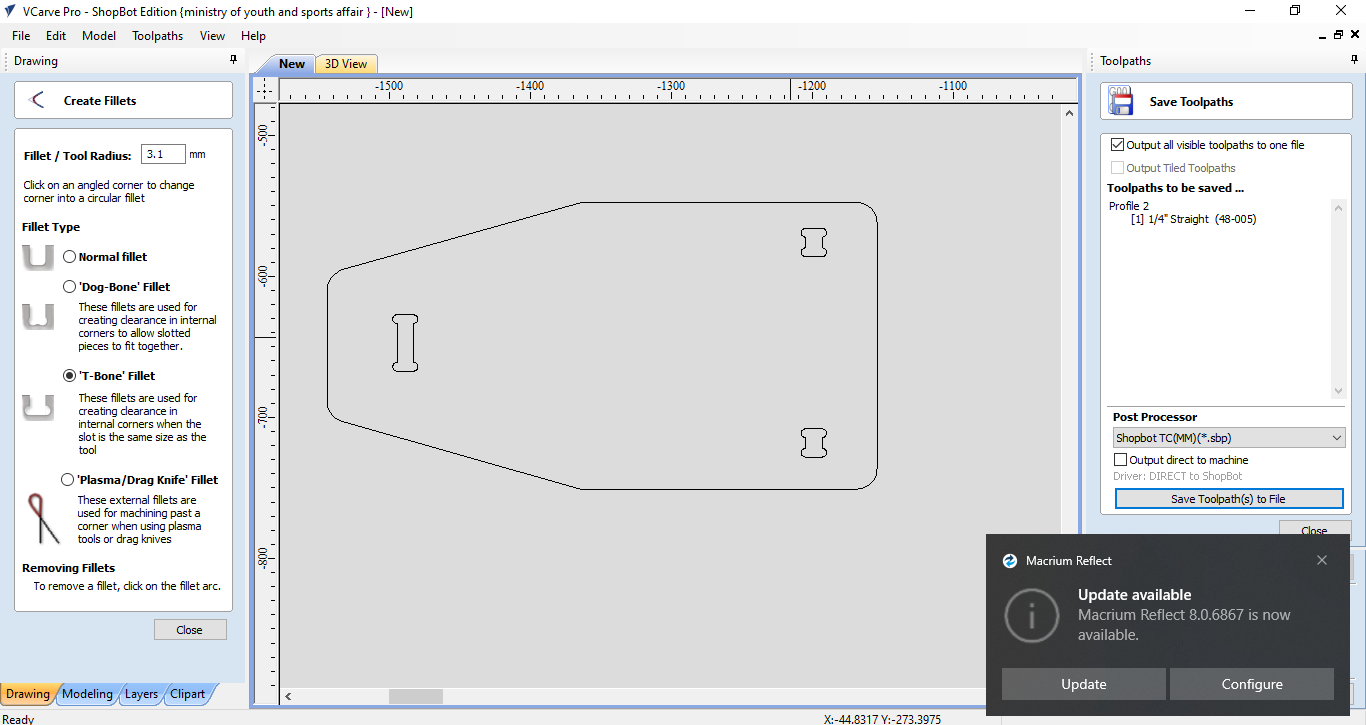
I opened the design on the computer connected to the machine. First I had to add fillets. They are used to enable the millet to cut the corners of the joints in a design. There are 2 types of fillets I used:
The dog-bone fillet; for the outer corners
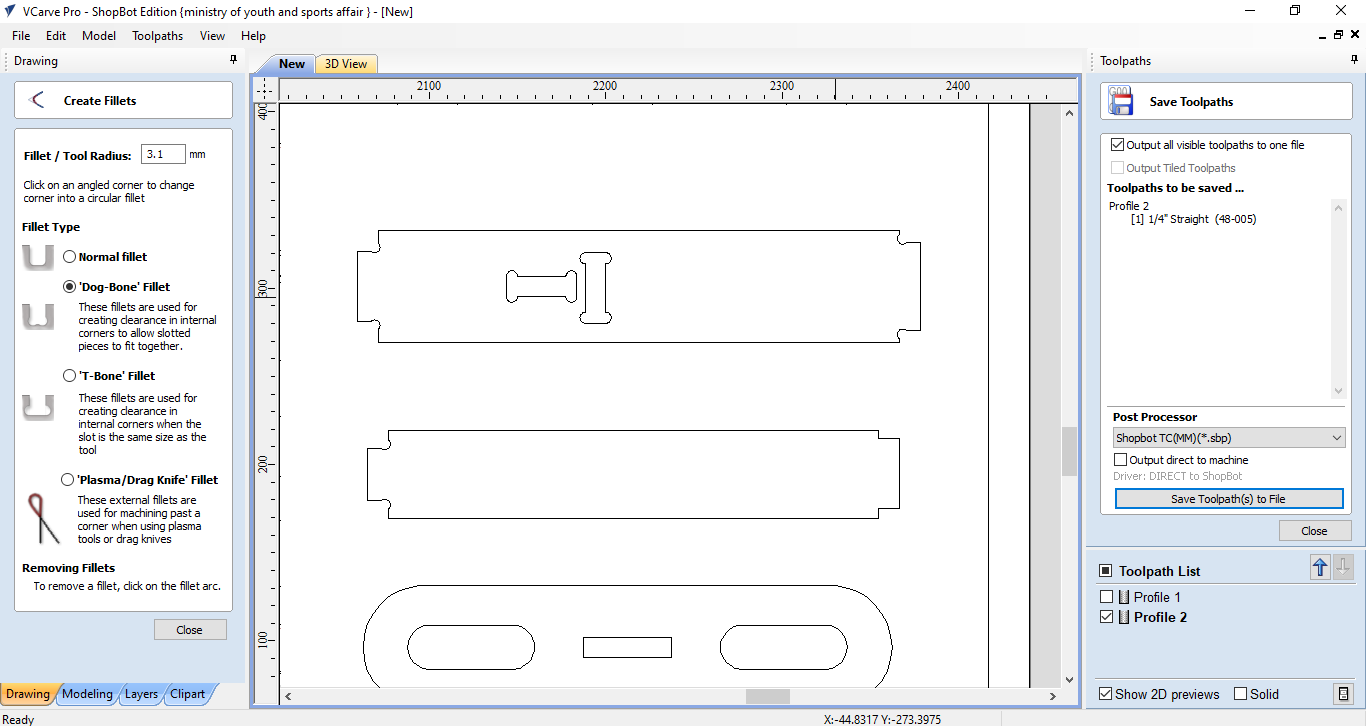
The T-bone fillet; for the holes
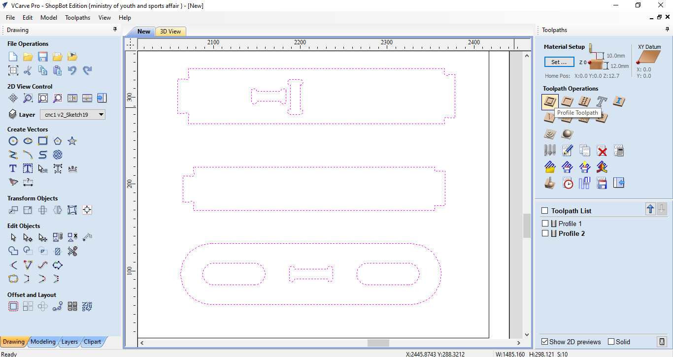
Then I had to fix the toolpath. My design utilises only one type of toolpaths which is profile?
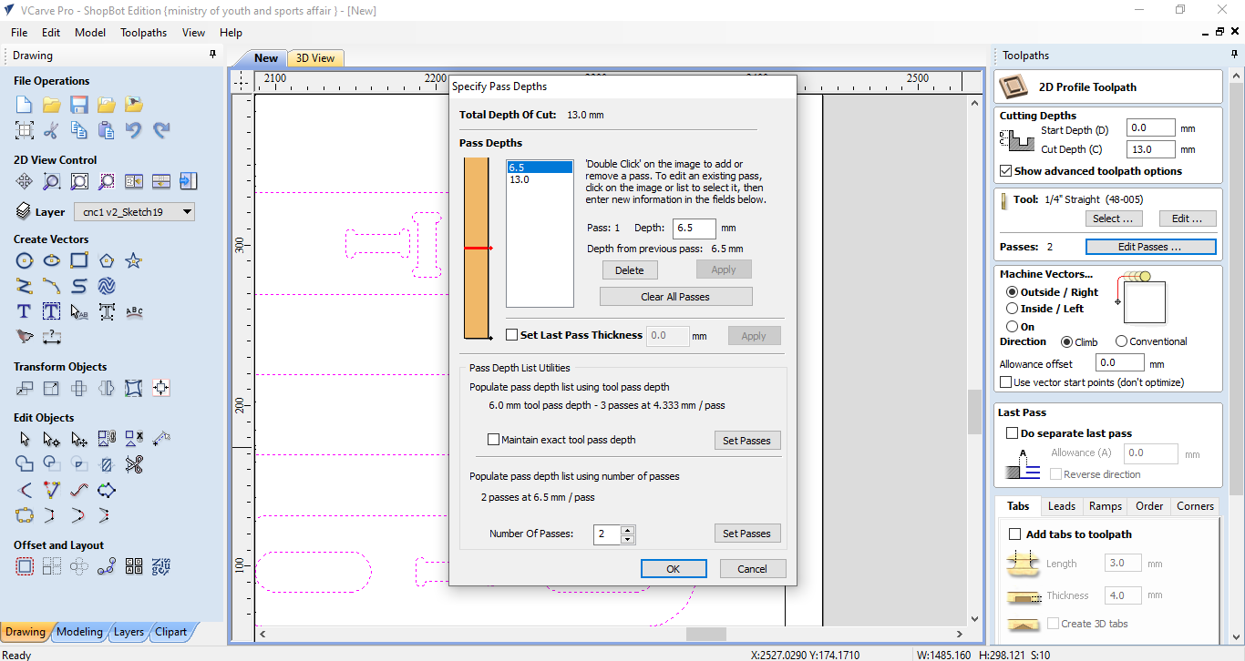
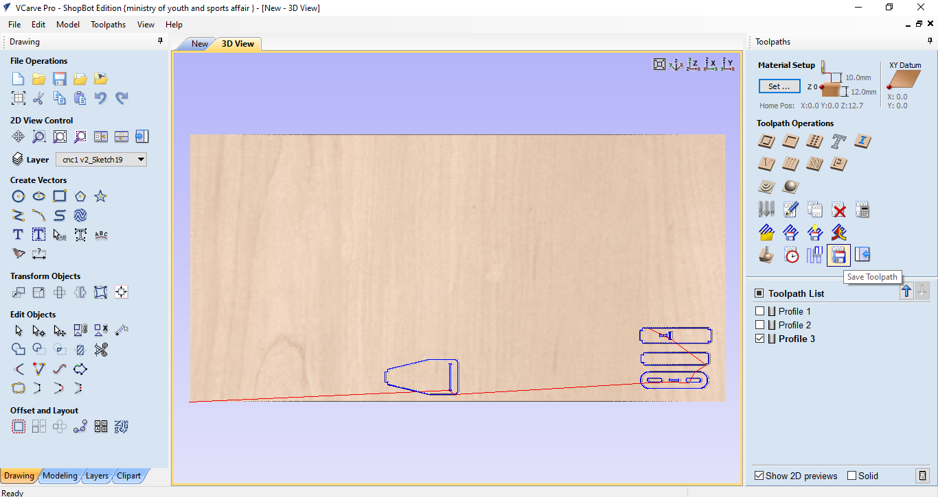
After that, I chose the number of passes I need which means the number of times the machine will cut my design since the material is 12mm thick and the millet height is less than that. In my case, 2 passes were sufficient to cut the plywood and 2 passes are better to save time.
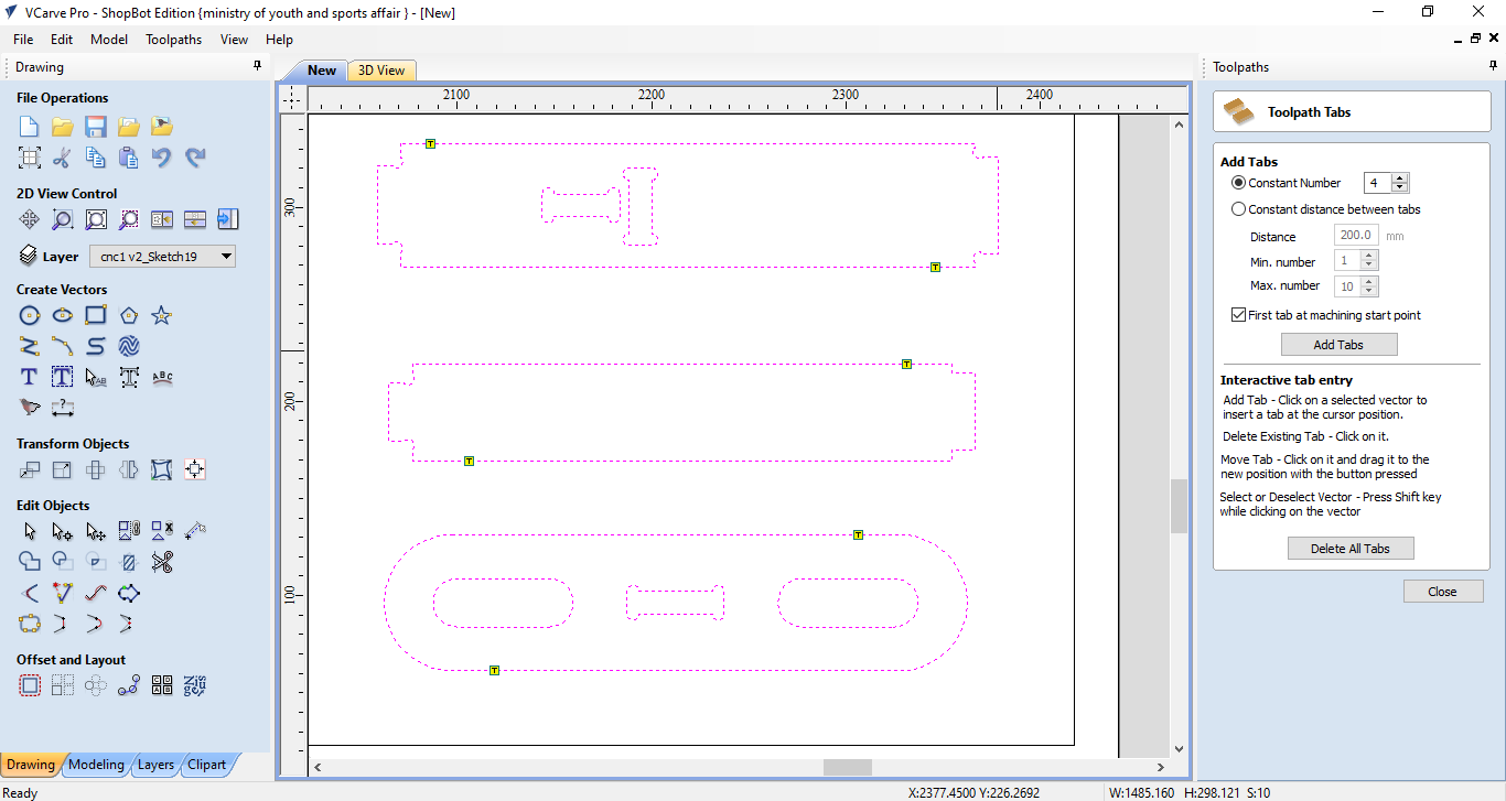
Before cutting the design, we added tabs, which are small areas that won’t be cut during cutting the design, to ensure that the parts will not move during the cutting process.
Finally, we run the simulation to see how the design will be cut. The red line indicate the order of parts that will be cut.
Sanding and Assembling
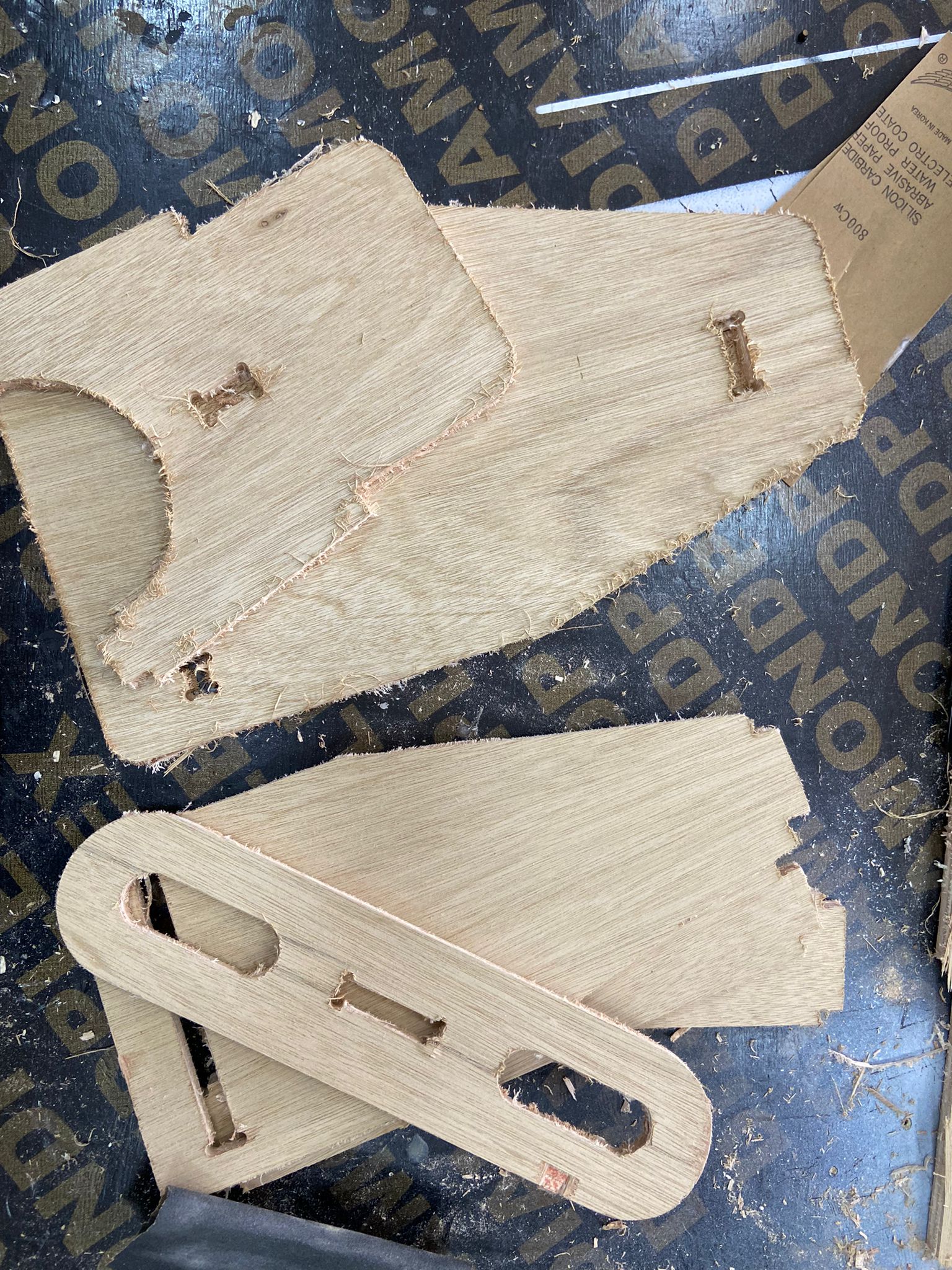
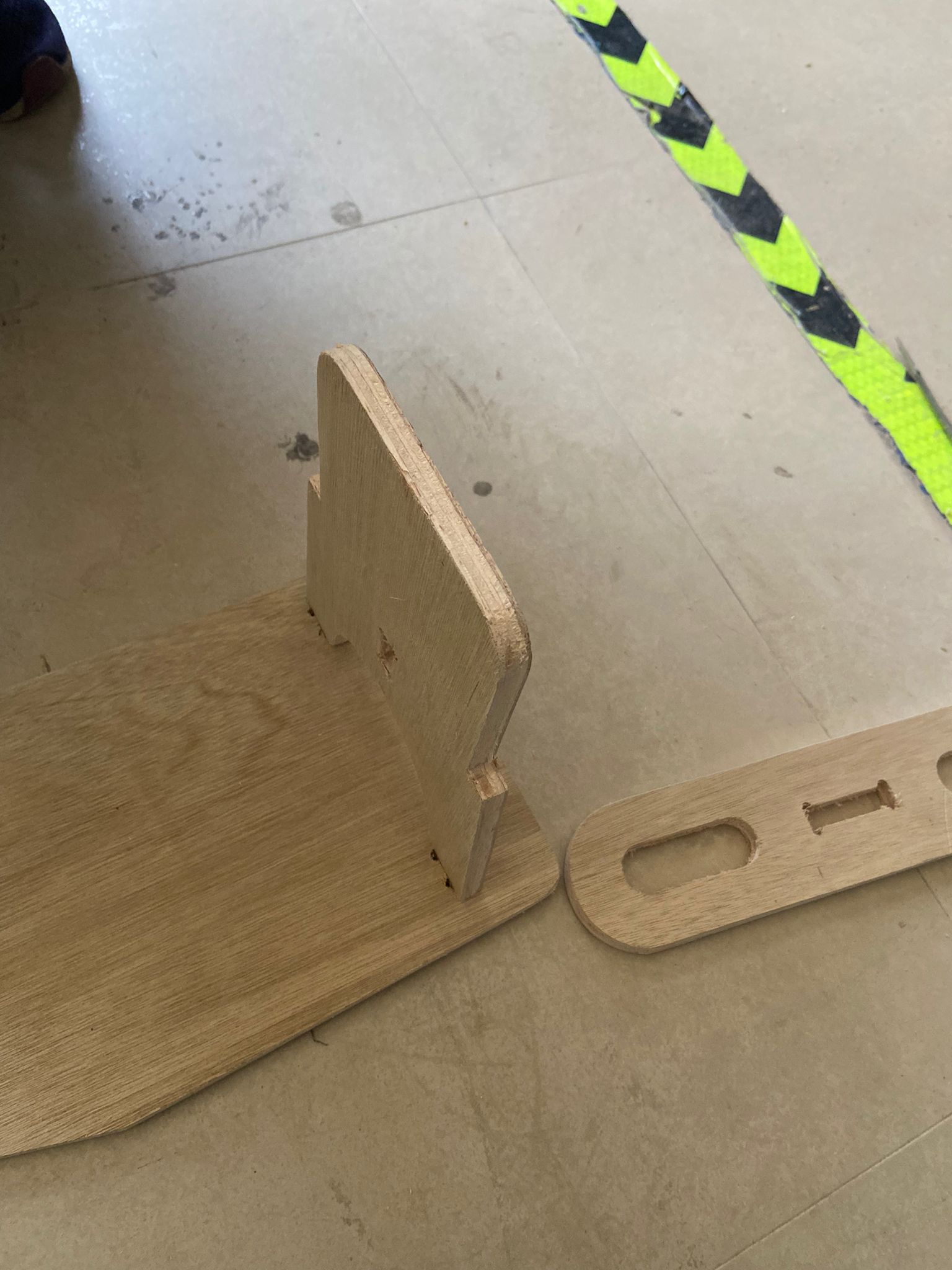
Those are the parts of my scooter cut and ready to be sanded. For sanding I used a metal file and sanding paper.
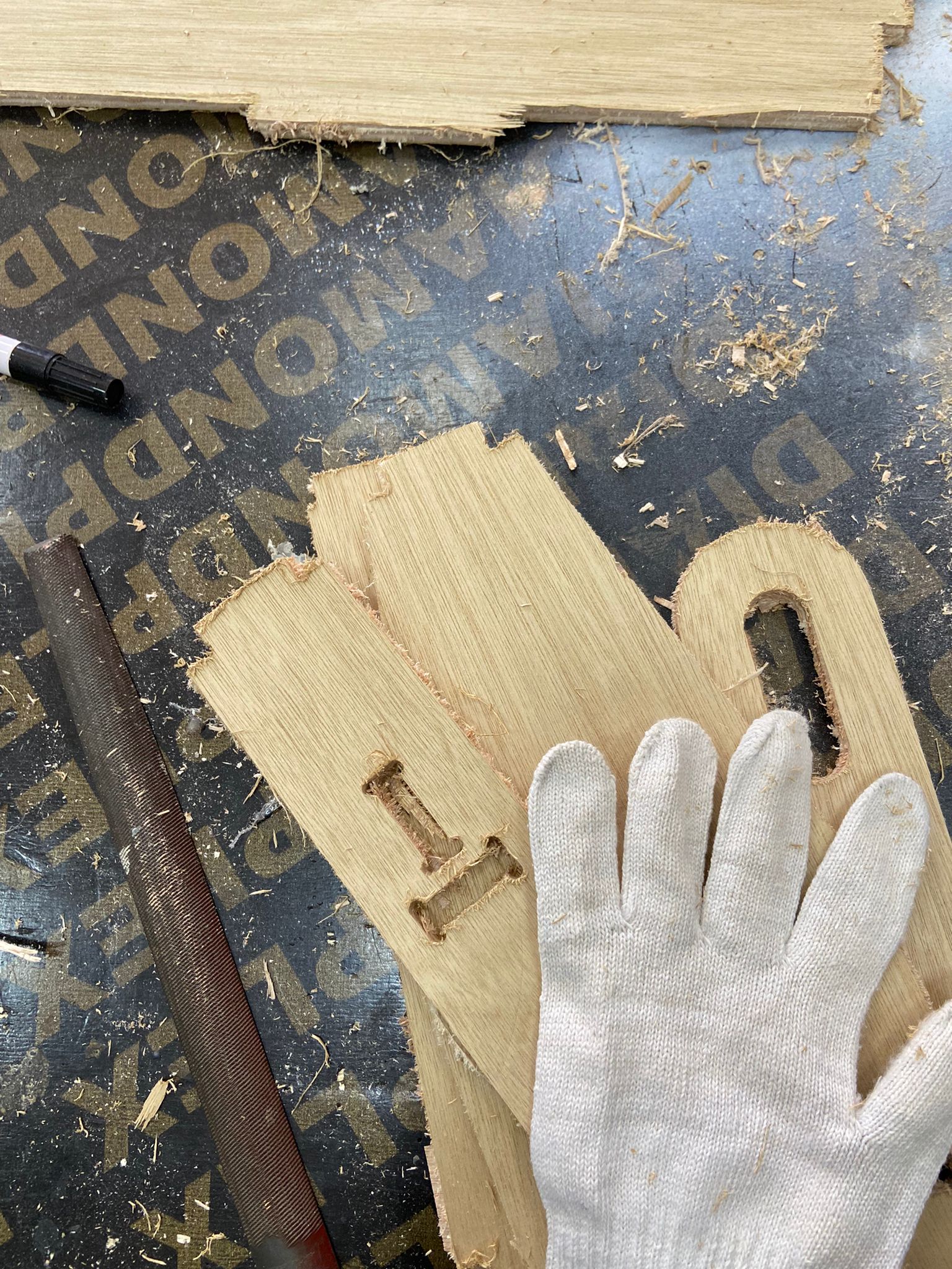
The parts at the top are not sanded yet and the parts at the bottom are sanded but not cleanly.
To sand the parts cleanly and quickly I used a sanding machine which saved some time.
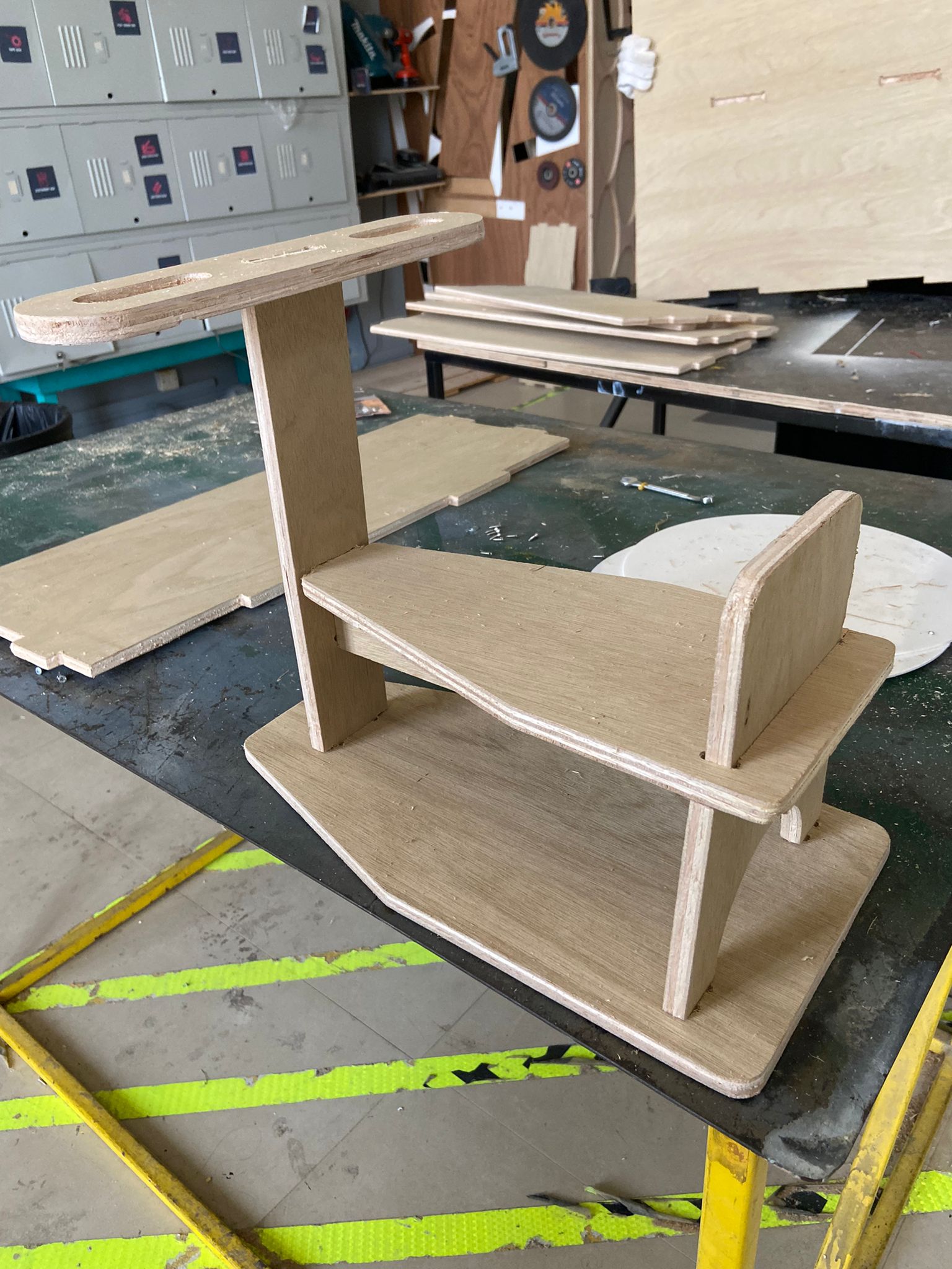
After sanding all the parts, I tried to assemble them using a mallet hammer. The back attached perfectly in the base so I worked with the other pieces.
The Result!
This is what the scooter looks like after the assembly.
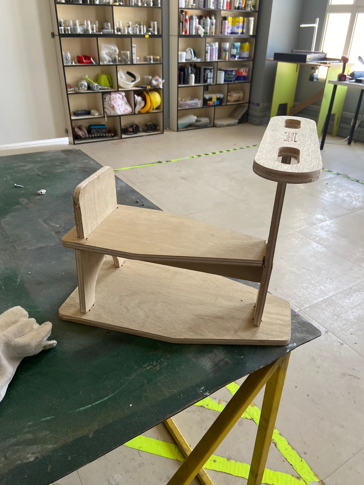
Note: the scooter still needs tires but they were not available at the time