3. Computer controlled cutting
In this week, I have learned to use the vinyl cutter to cut thin sheets and use the laser cutting machine to cut cardboard
Vinyl Cutting Machine
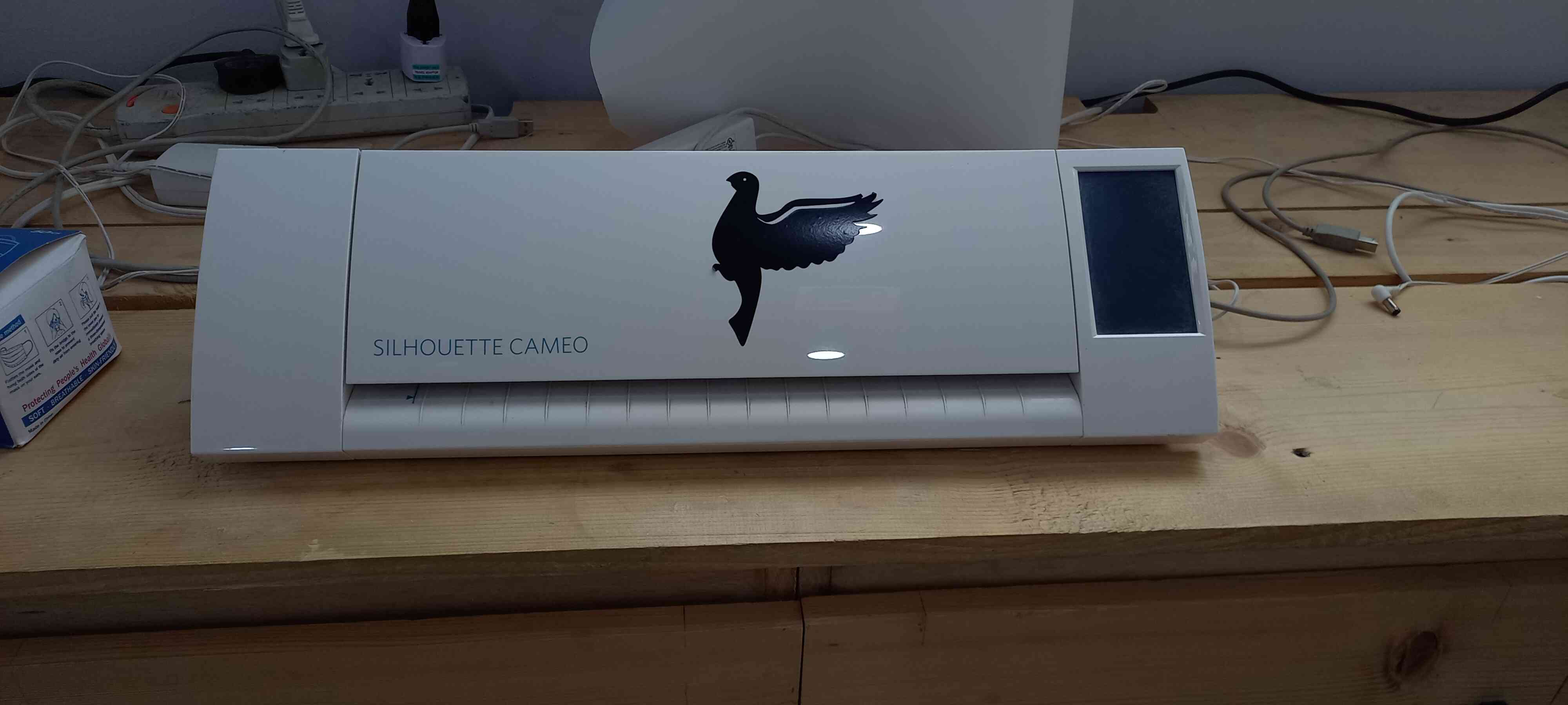
It is a Computer controlled cutting machine that cuts thin vinyl sheets using a small knife.
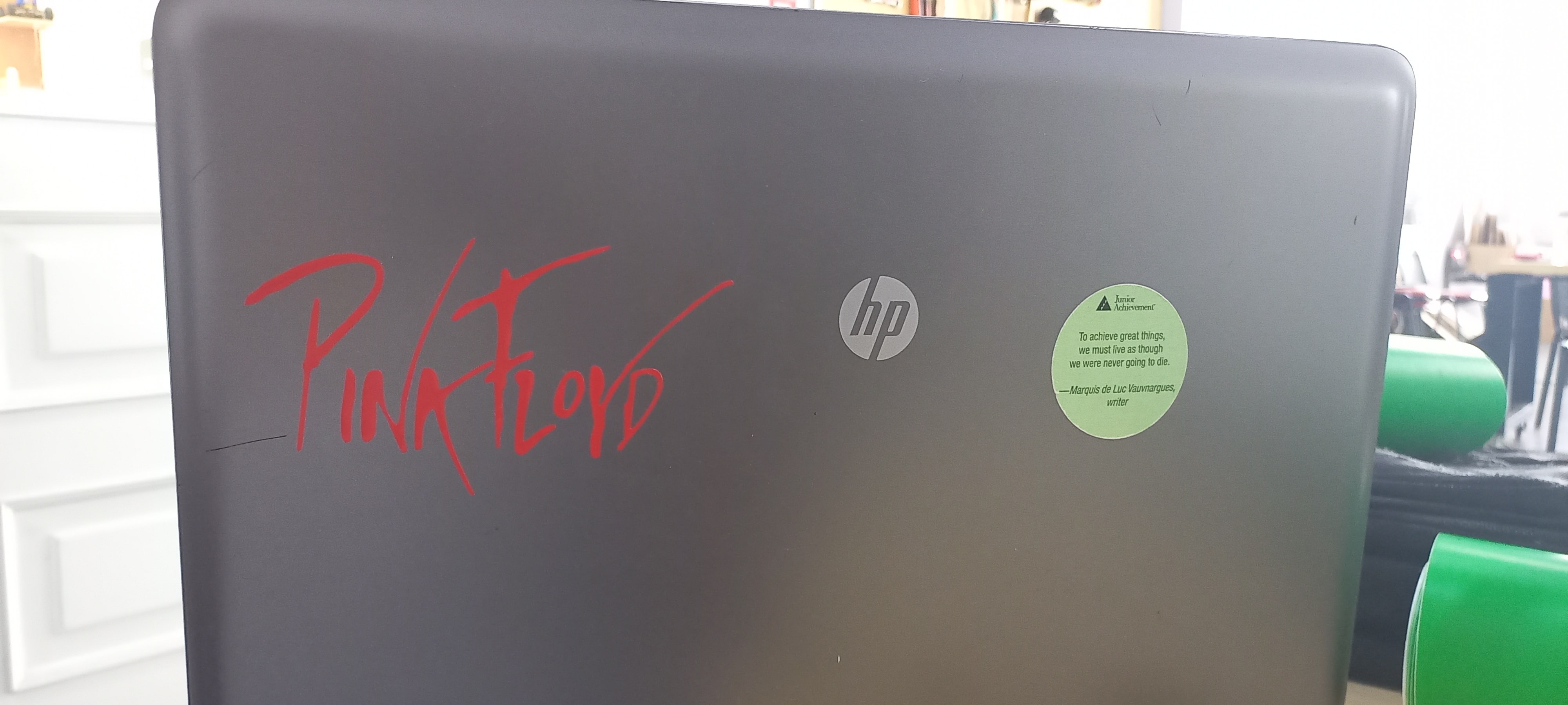
It is used commonly to make stickers from silhouette images and in this assignment I have made a sticker for my laptop, using this machine.
How does it work?
The vinyl cutter is controlled by a computer that monitors how and were the blade cuts on the vinyl sheet, and to simplify the process , first you choose an image and send it to a software that defines the edges of the image, then you send the file to the cutter using a USB cable.
How to start?
-
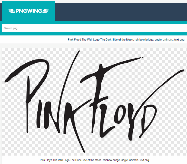
Choose a Silhouette image (png format)
-
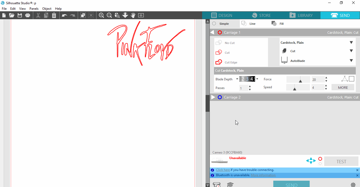
Downloaded Silhouette Studio to send the image to the cutter
-
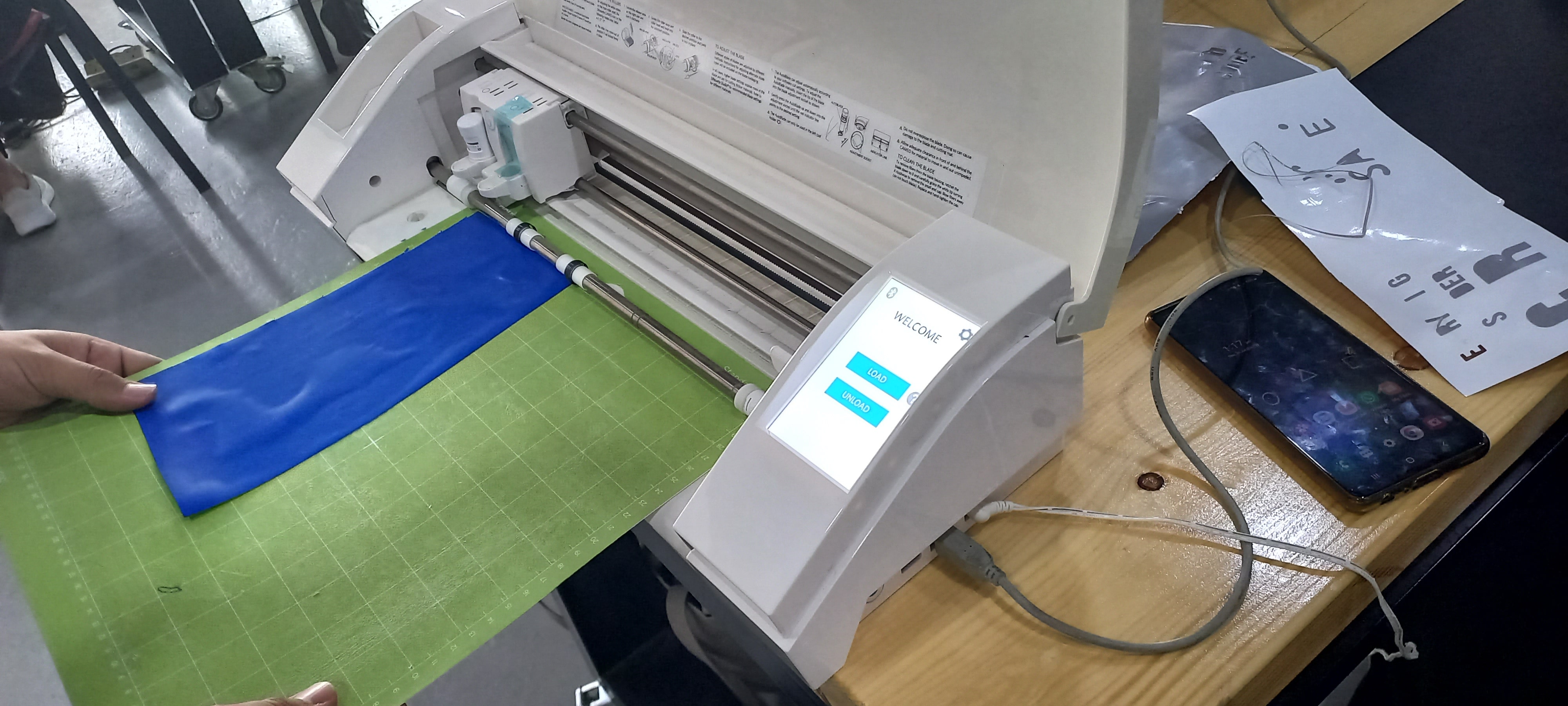
Start cutting
Steps:
Step 1: Choose a Silhouette image
Step 2: Use Silhouette Studio to trace the lines of the image
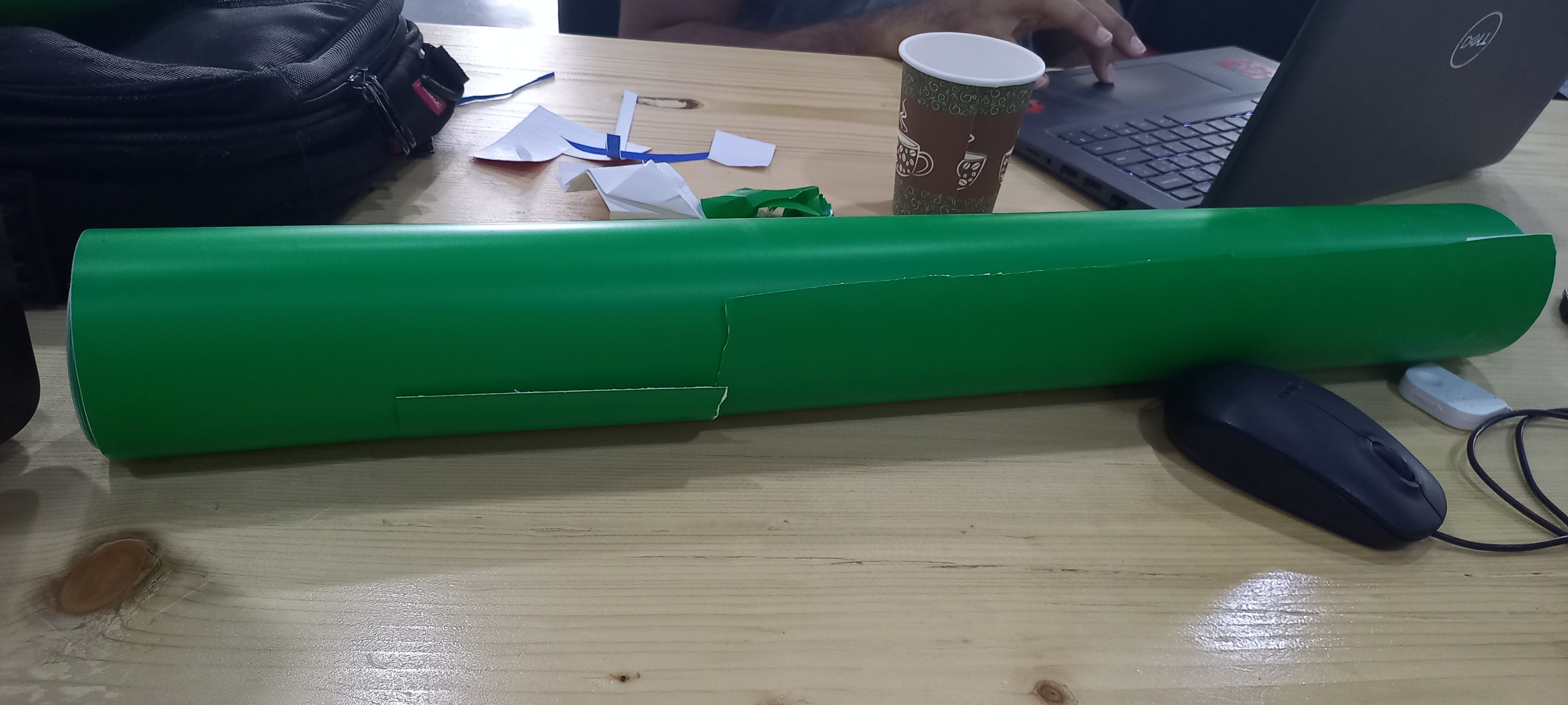
Step 3: Choose vinyl color
The results:
Laser Cutting Machine
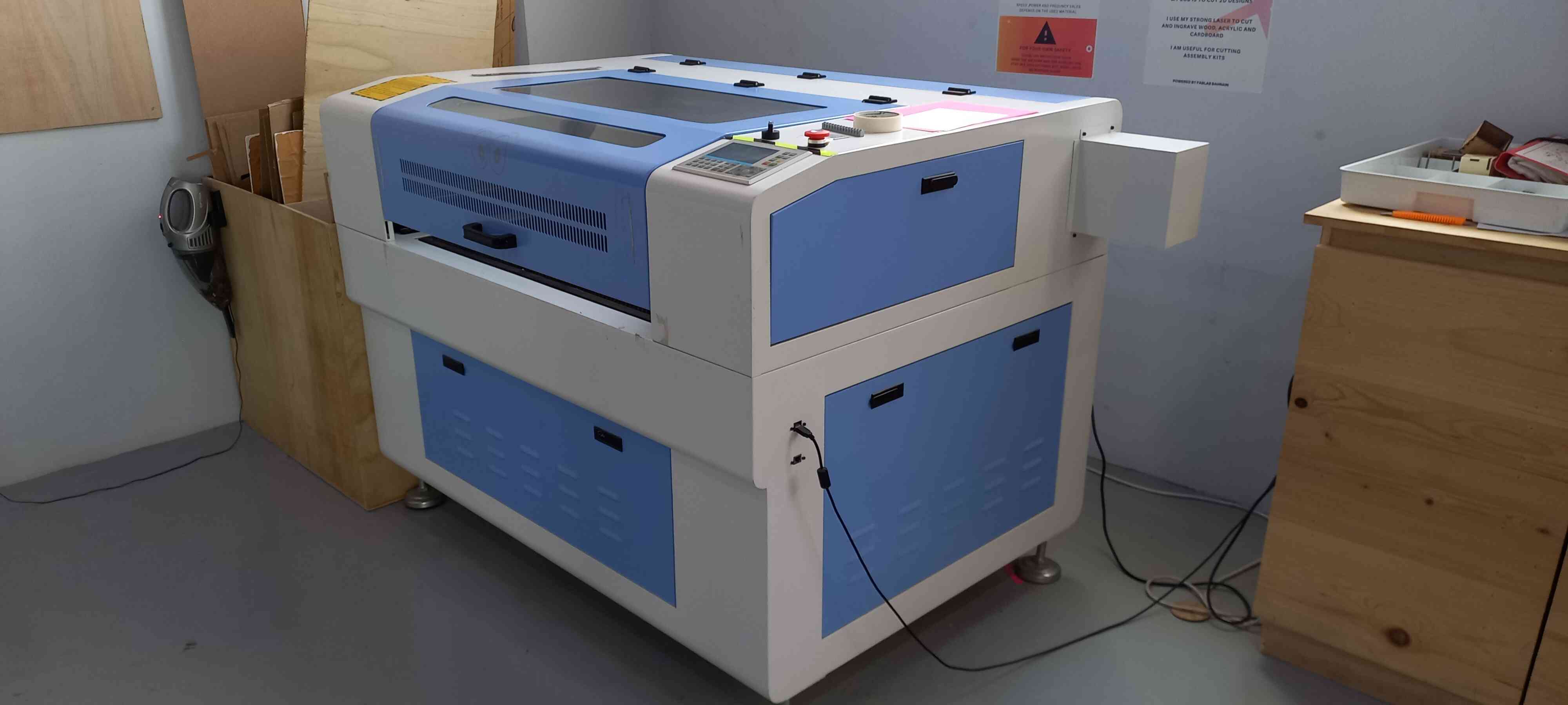
The Laser Cutting machine is a computer controlled cutting machine that cuts and engraves cardboard, wood and even thin plates of acrylic.
This machine uses a laser head that penetrates the workpiece (wood, acrylic etc.) instead of the blade/knife in the vinyl cutter.
Group Assignment
Our task was to basically calibrate the laser cutting machine and test different cutting settings.
Our first step is to do a focus test, which means that we needed to adjust the distance between the laser head and the workpiece.
We started by drawing a line in the software
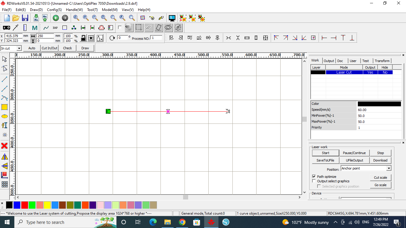
Then we tilted the workpiece and we started the cut
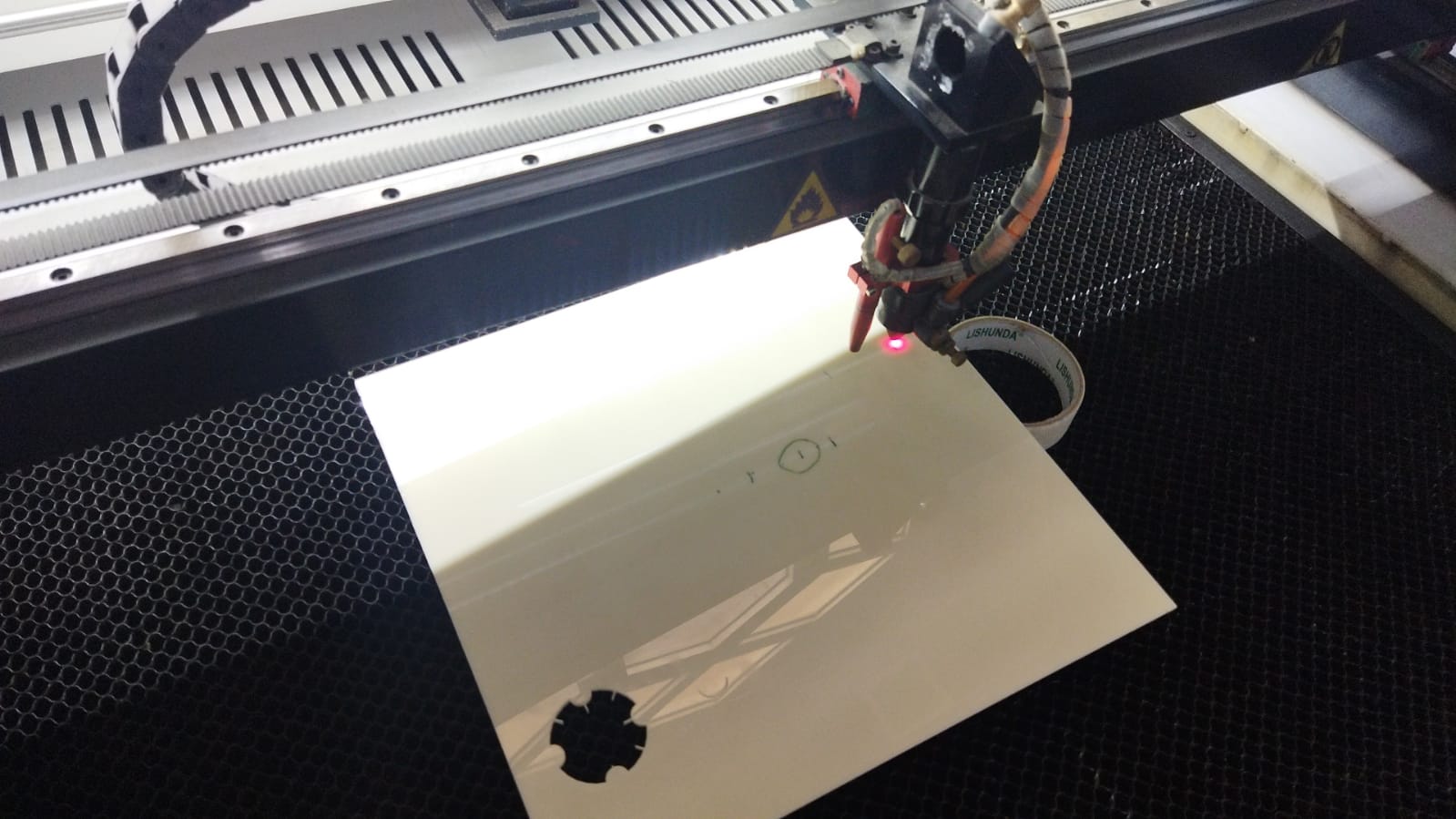
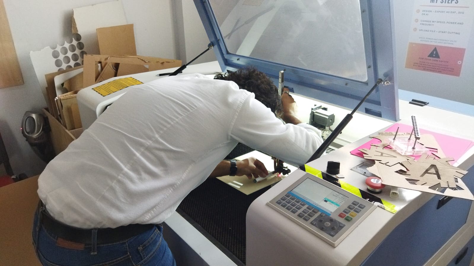
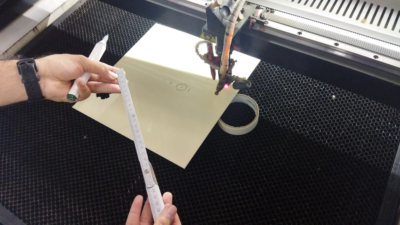
After locating the best point on the line that the laser cut, we measured the distance between the point and the laser head, these are our results:
- we found that a distance of 8mm is the perfect distance
- It allowed the laser beam to hit the workpiece in concentrated way
The second step was to calibrate and find the best cutting speed.
We started by drawing five 20x20mm squares and we set the power to 30% and we increased the speed from 20 mm/s to 80 mm/s with increments of 15.
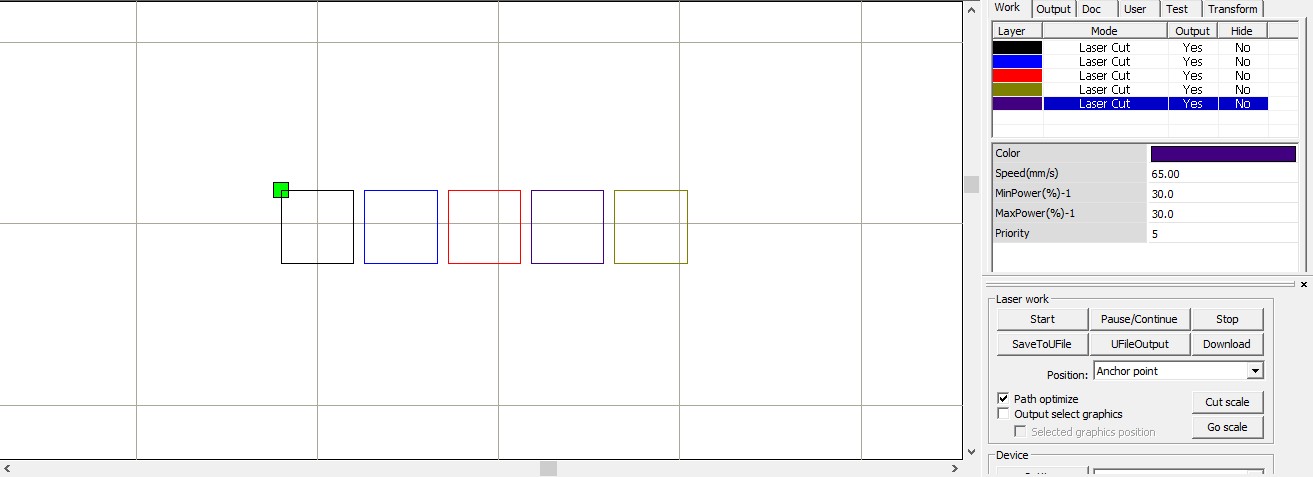
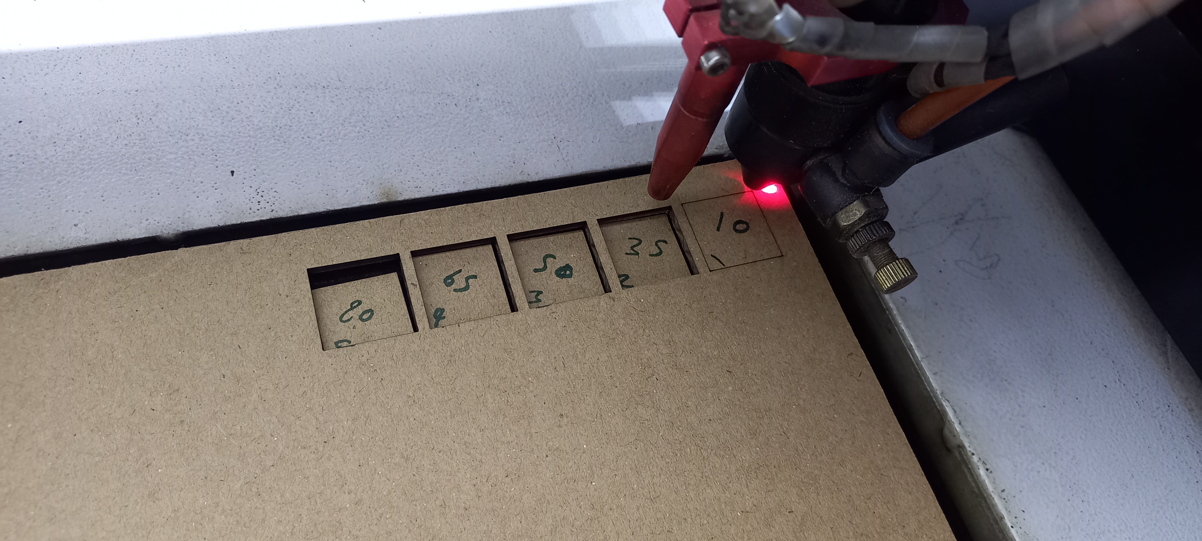
The squares that were completely cut are squares with the speed of 35,50,65 and 80 mm/s.
The fourth step was to calibrate and find the best power percentage.
With the same five square designs, we set the speed to 60 mm/s and we increased the power from 20% to 80% with increments of 15.
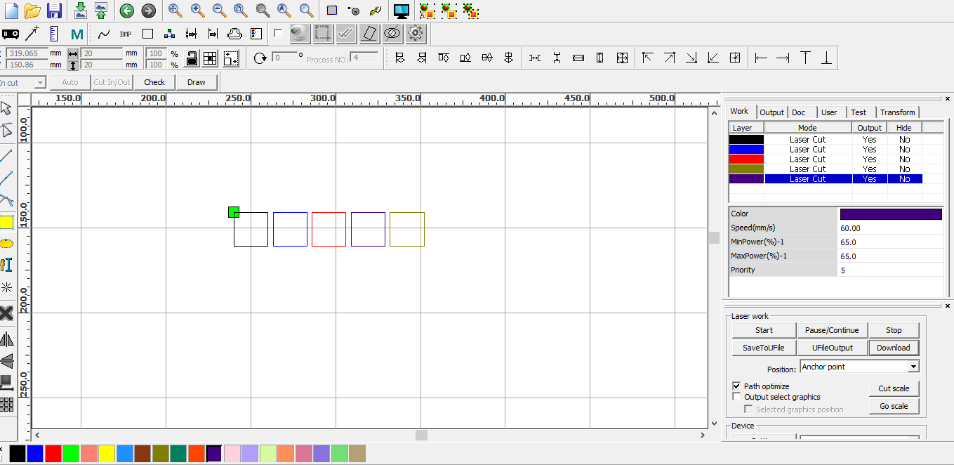
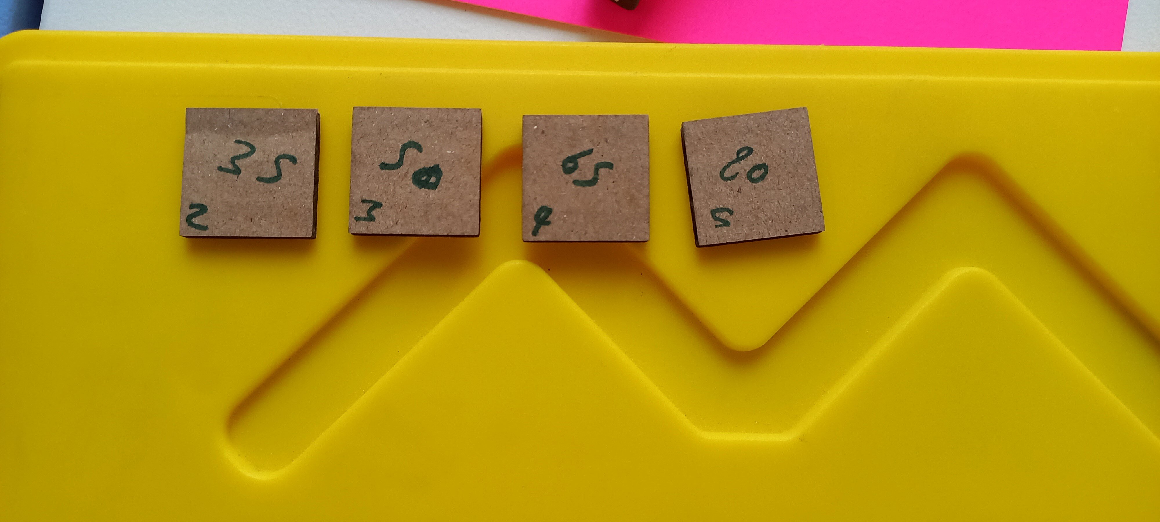
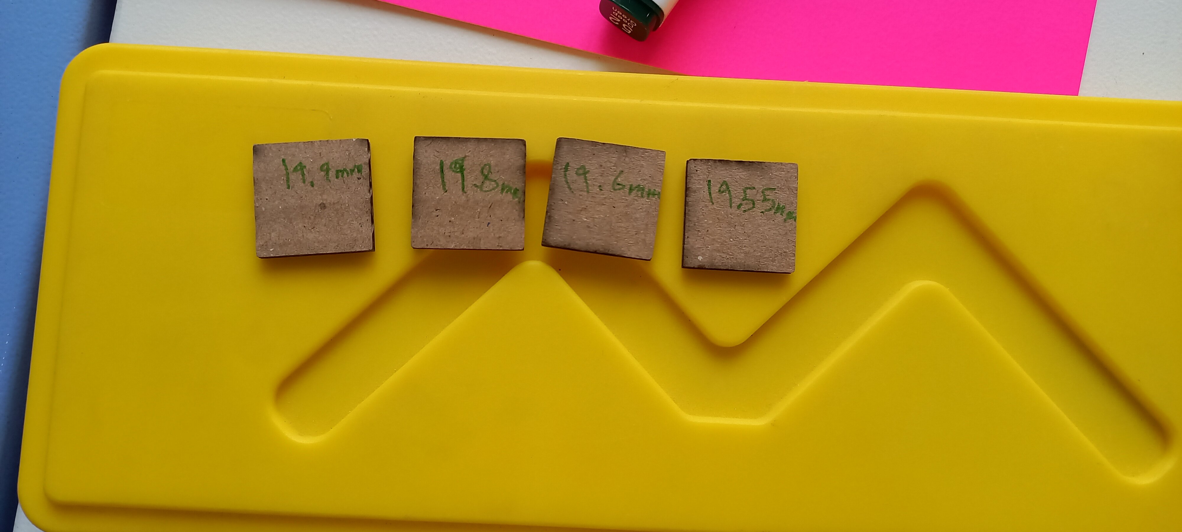
The squares that were completely cut are squares with the power of 35,50,65 and 80%, and with a second test related to the power, we measured the dimensions of each square to find the best power percentage with the lowest kerf.
The closest square to the original dimensions of 20mm x 20 mm was the square with the power of 35%
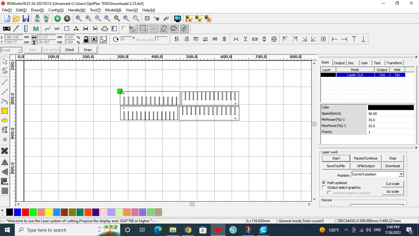
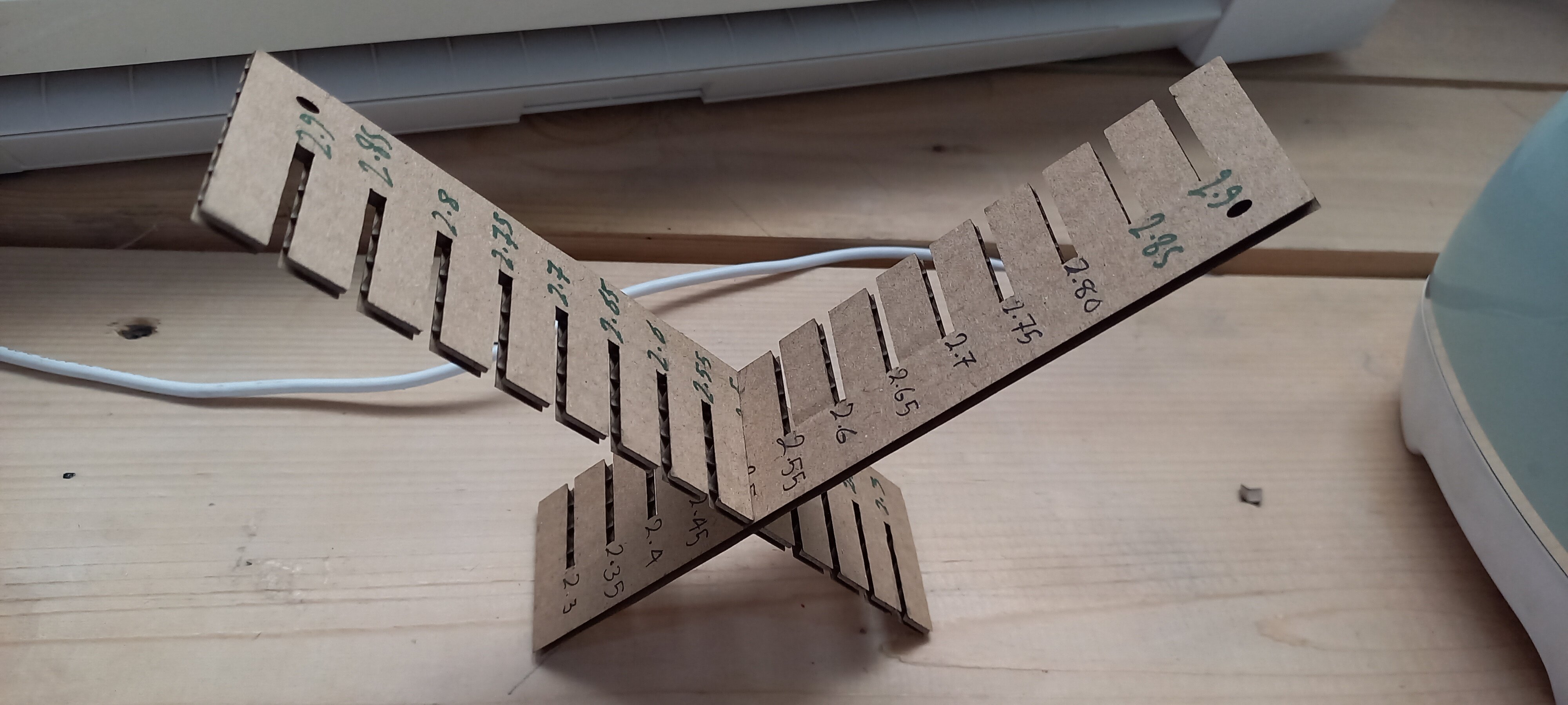
The sixth step was to find the best clearance for a press fit joint.
We started by drawing a design with a clearance ranging from 2.9 to 1.65 mm, decreasing with increments of 0.05 mm.
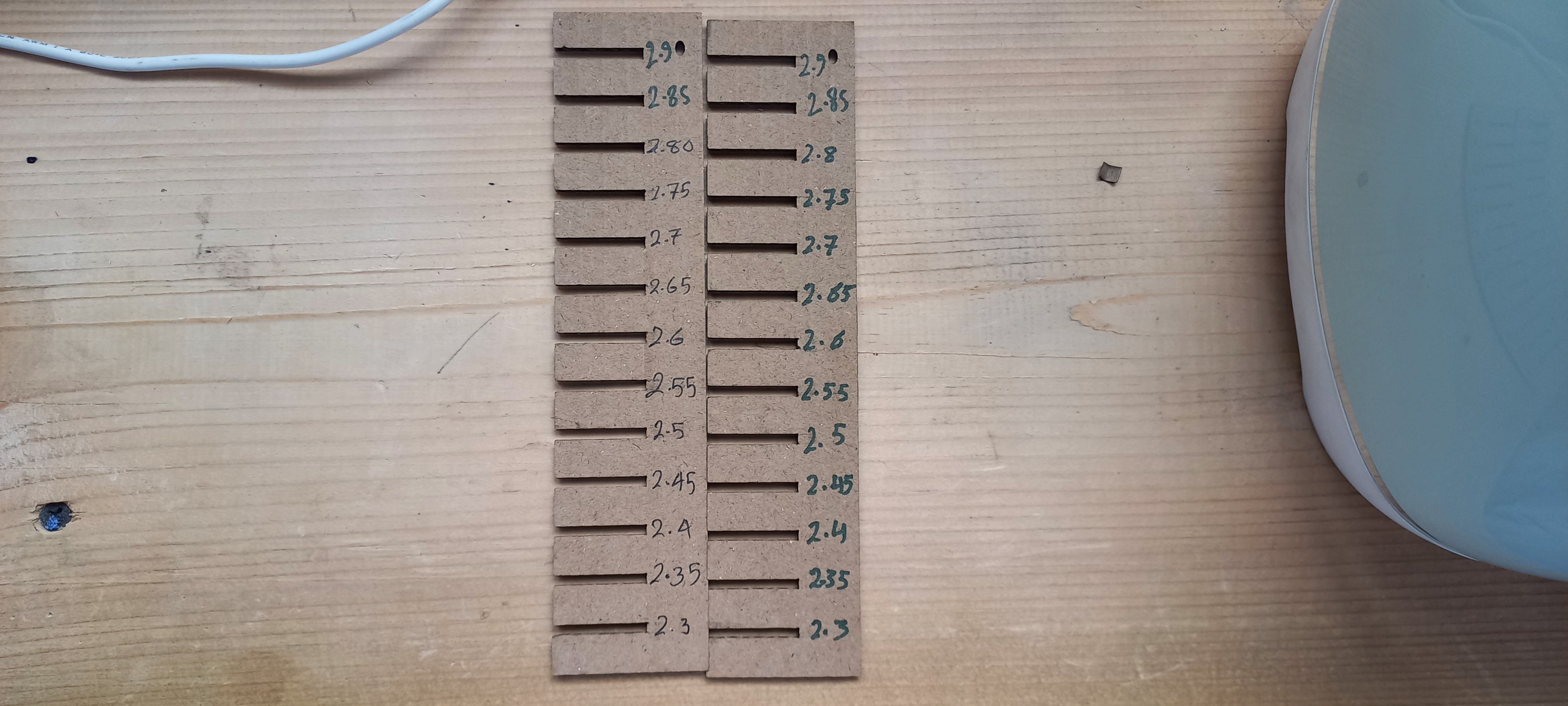
By testing the joints and trying to fit them, the best clearance was 2.5 mm.
Our results are
- Clearance: 2.5mm
- Speed: 40mm/s
- Power: 35%
Individual Assignment
After calibrating the Laser Cutting Machine, I started designing a model in Fusion 360.
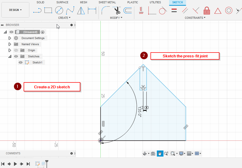
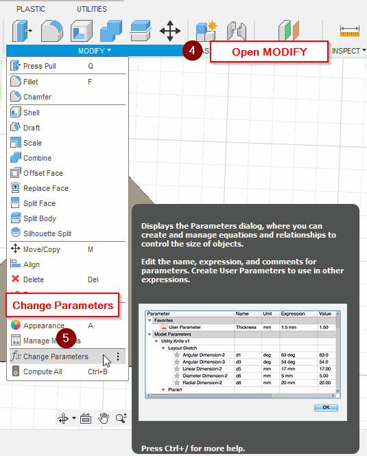
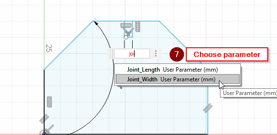
Add a joint length and width parameters:
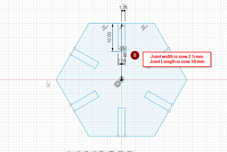
- Joint_width = 2.5 mm
- Joint_Length = 10 mm
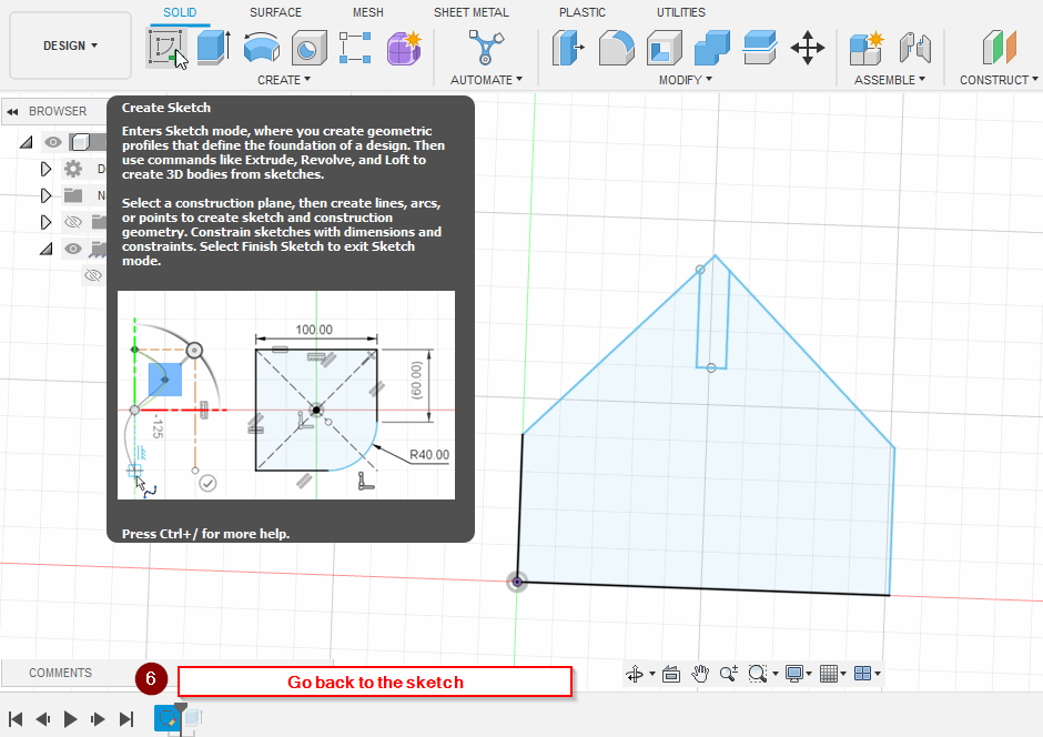
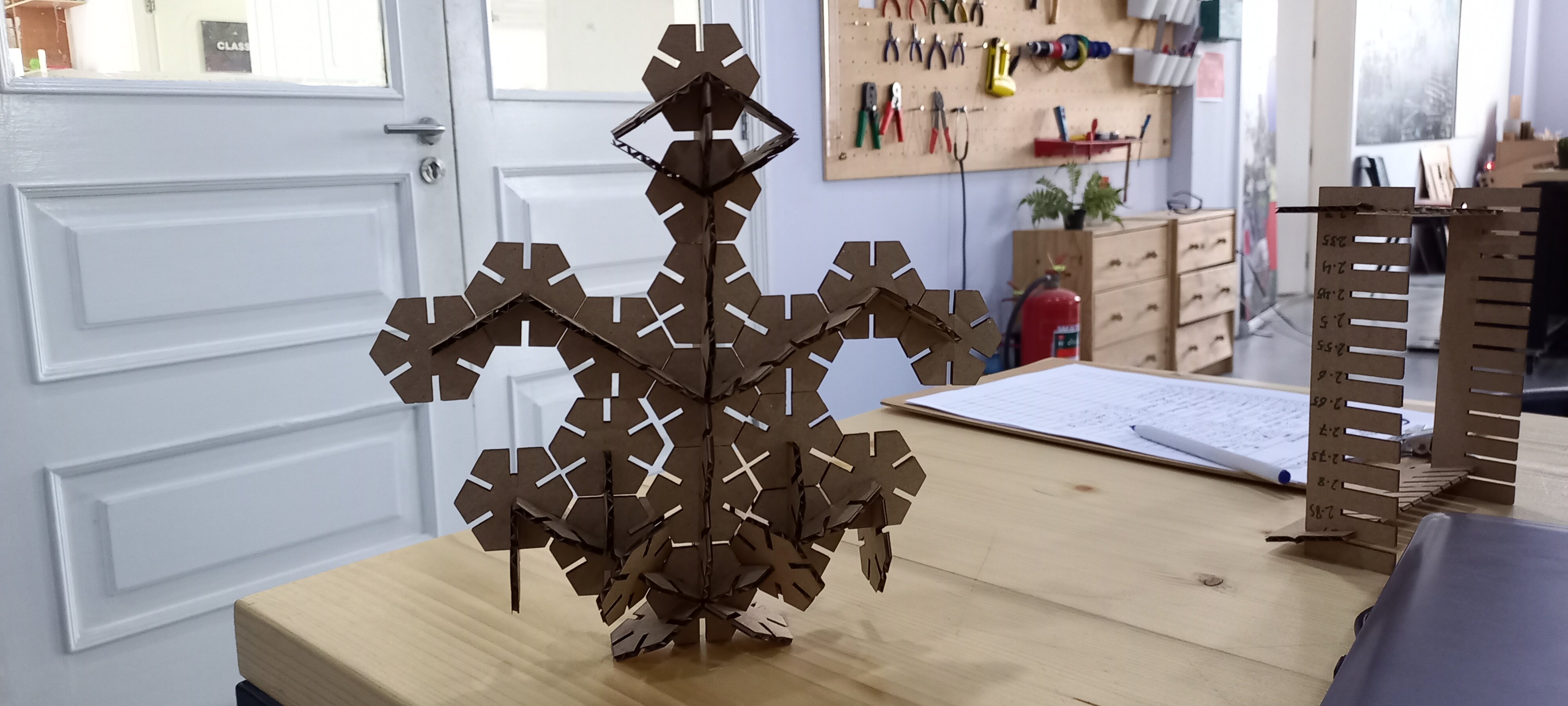
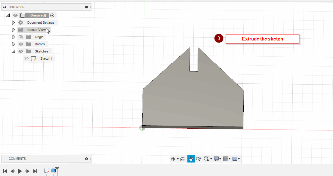
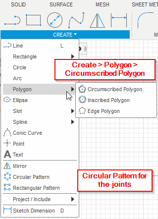
Note: I have changed my design to a hexagonal shape
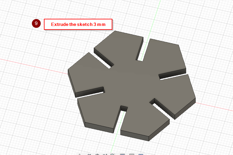
After that I’ve saved the model in a .dxf format, then I sent it to the cutter
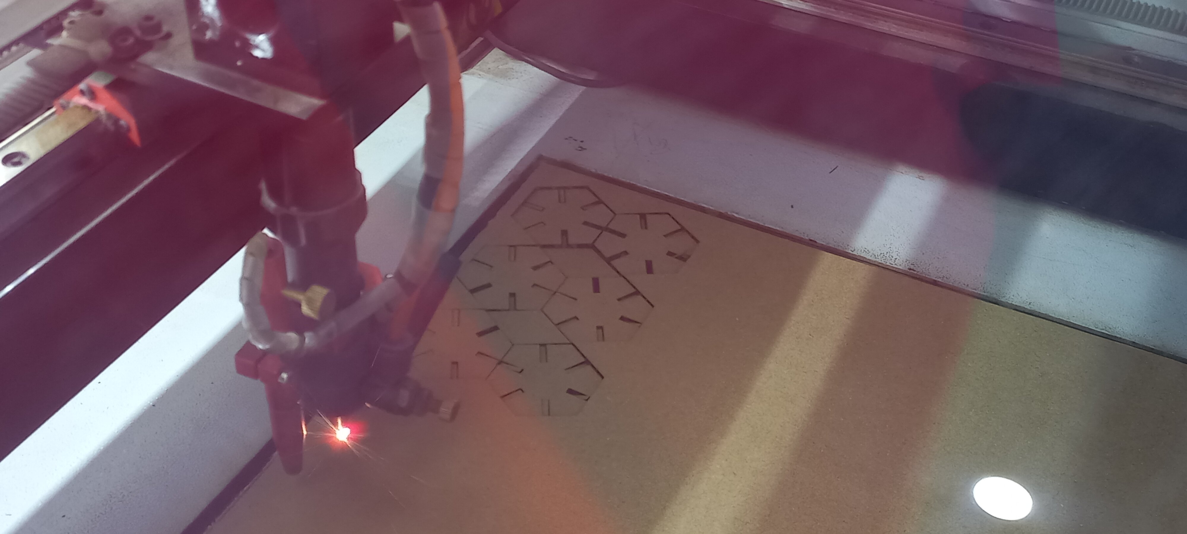
- Original file
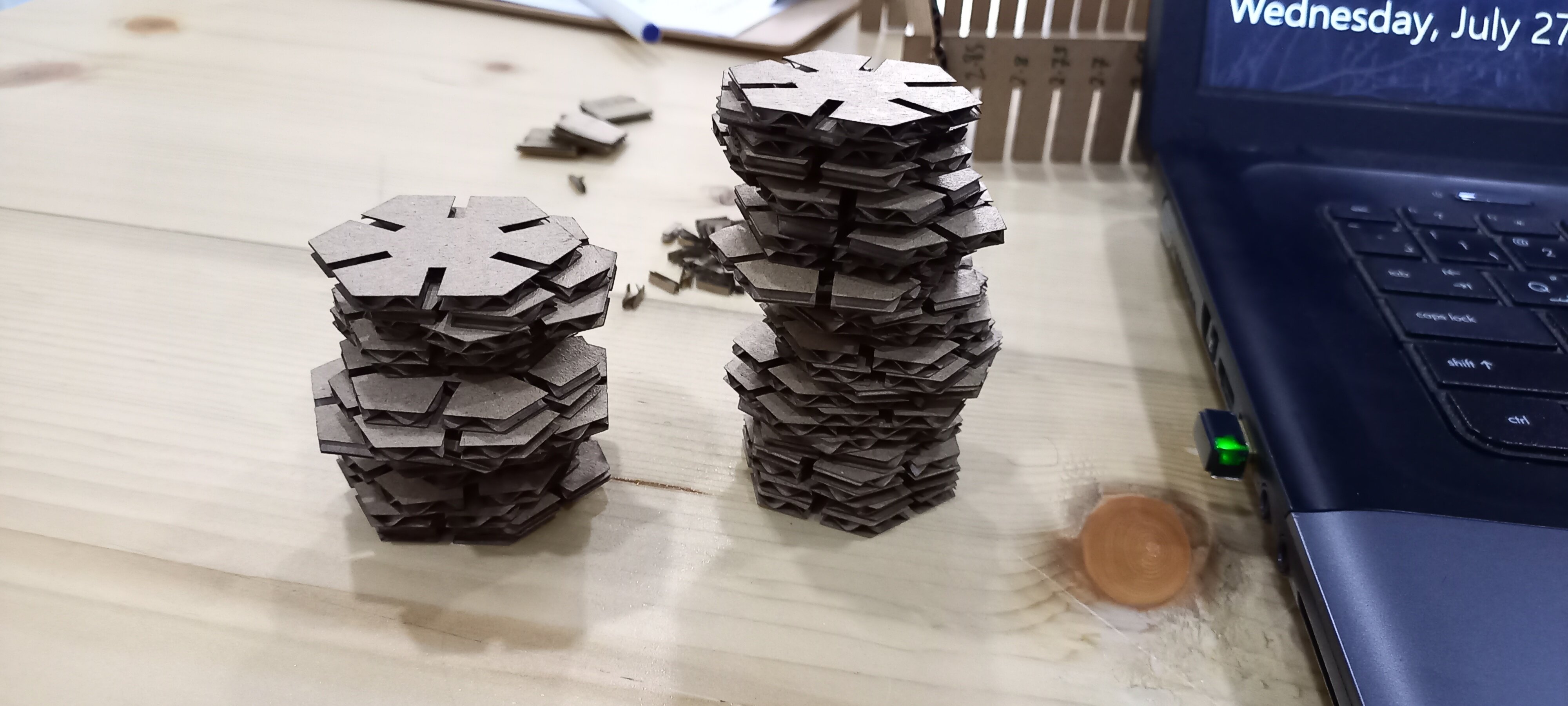
The result:
Hexagonal Eagle