7. Input & Output device
In this assignment, I have programmed a microcontroller to operate input/output commands using different types of input/output devices
What are Input & Output devices?
Input and Output devices can be summarized in three points:
-
The Input device sends information/commands/data to the microcontroller
-
The microcontroller processes the data and gives it to the Output device
-
The Output device displays or acts correspondingly to that data
Types of sensors
Sensors are generally divided between analog and digital sensors, and the main types of sensors are:
- Position Sensors
- Pressure Sensors
- Temperature Sensors
- Force Sensors
- Vibration Sensors
- Piezo Sensors
- Fluid Property Sensors
- Humidity Sensors
- Strain gauges
- Photo Optic Sensors
- Flow and Level Switches
Individual Assignment
Task 1
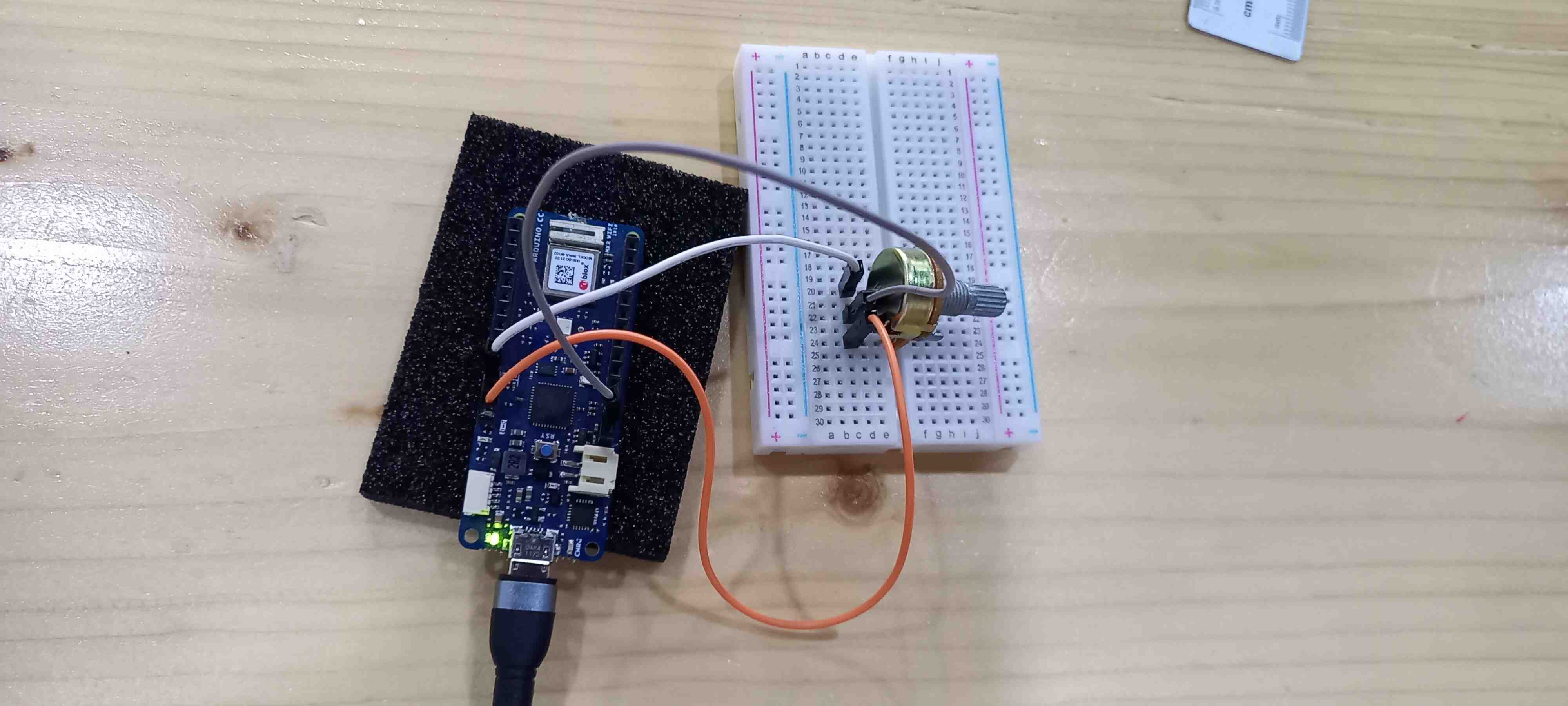
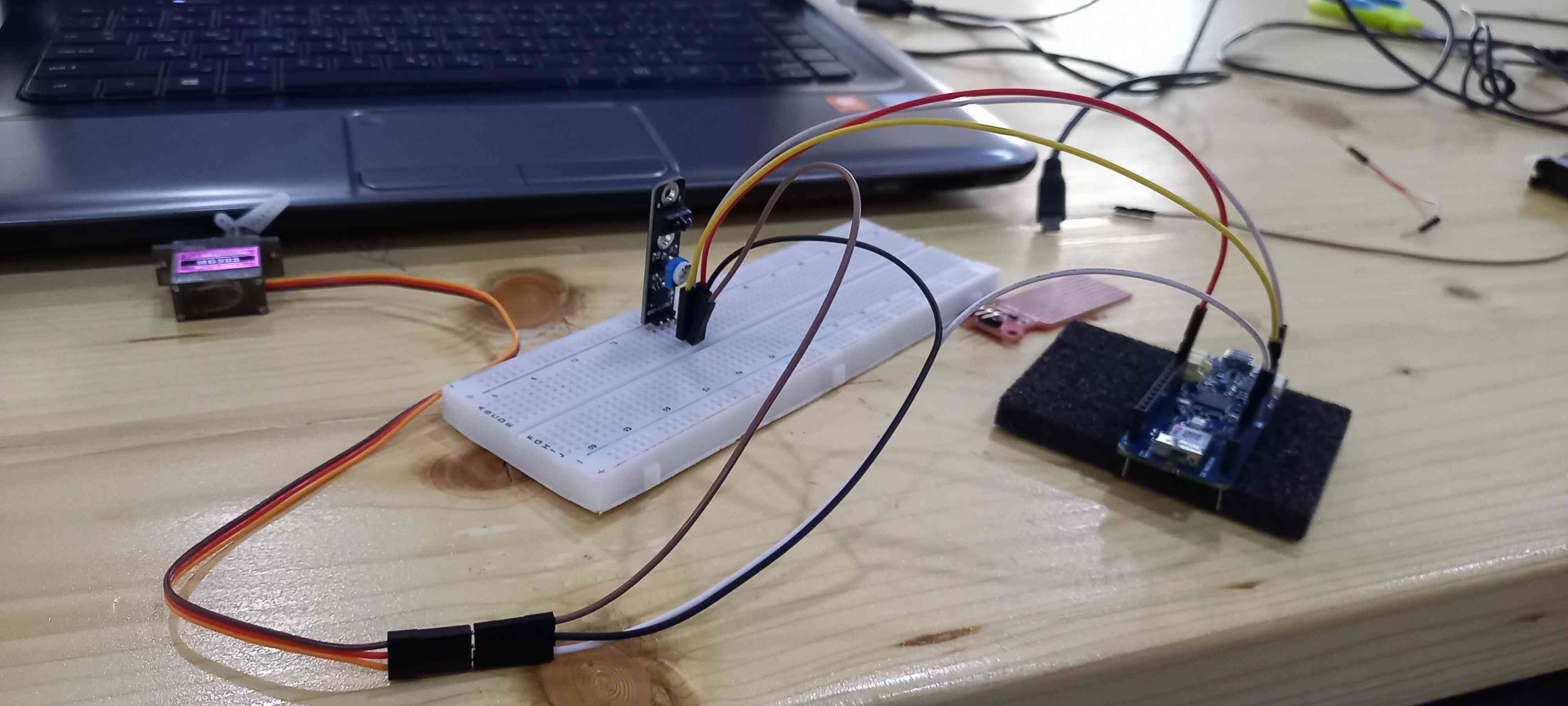
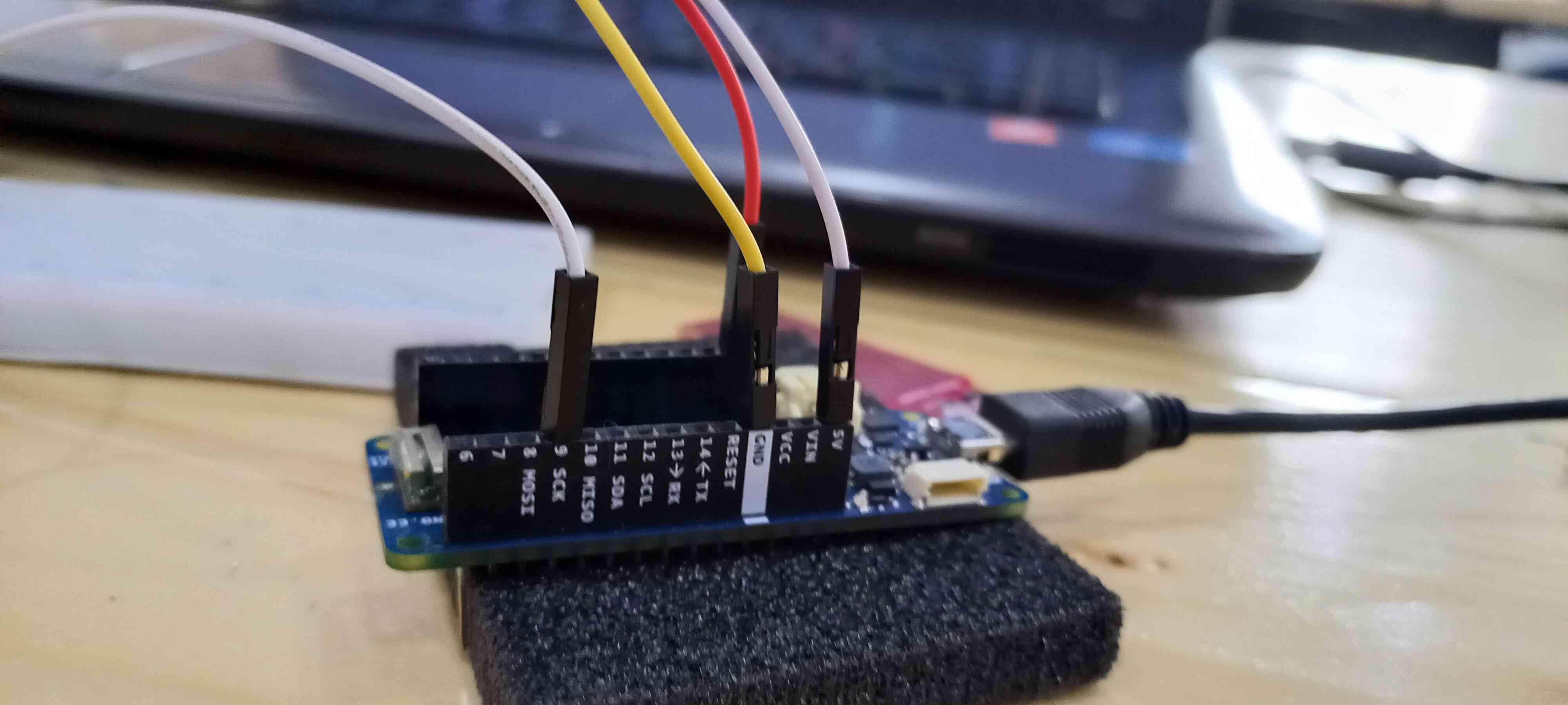
In this task, I programed the Arduino MKR 1010 to read the voltage of a sensor using the serial monitor. The sensor that I have worked with is the potentiometer B10K, which is an analog sensor that represents a knob in its shape and movement.
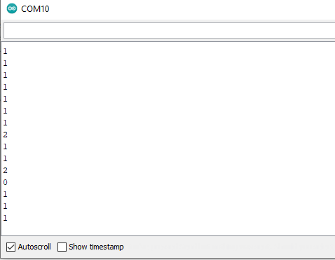
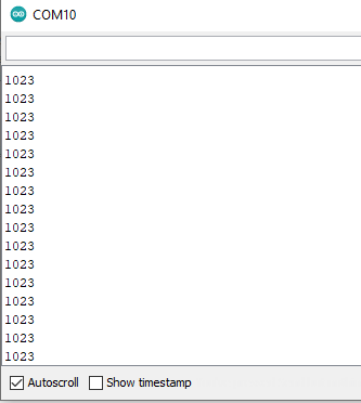
“The Arduino boards have a circuit inside called an analog-to-digital converter or ADC that reads this changing voltage and converts it to a number between 0 and 1023. When the shaft is turned all the way in one direction, there are 0 volts going to the pin, and the input value is 0. When the shaft is turned all the way in the opposite direction, there are 5 volts going to the pin and the input value is 1023. In between, analogRead() returns a number between 0 and 1023 that is proportional to the amount of voltage being applied to the pin.”
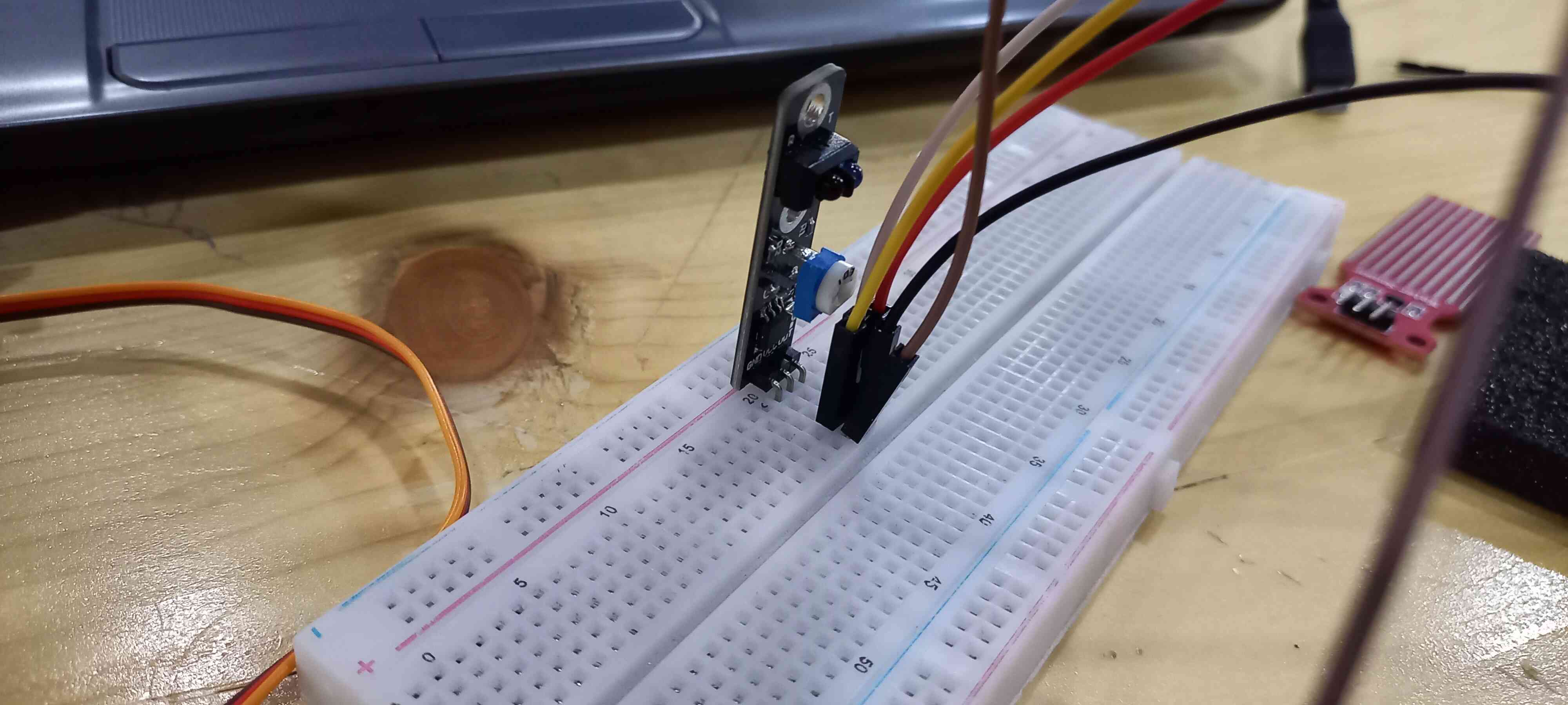
Connect the potentiometer with the board
Minimum voltage shows the value 0 on the serial monitor corresponding to 0 volts
Maximum voltage shows the value 1023 on the serial monitor corresponding to 5 volts
- Using Water Sensor
/*
Controlling a servo position using a potentiometer (variable resistor)
by Michal Rinott <http://people.interaction-ivrea.it/m.rinott>
modified on 8 Nov 2013
by Scott Fitzgerald
http://www.arduino.cc/en/Tutorial/Knob
*/
#include <Servo.h>
Servo myservo; // create servo object to control a servo
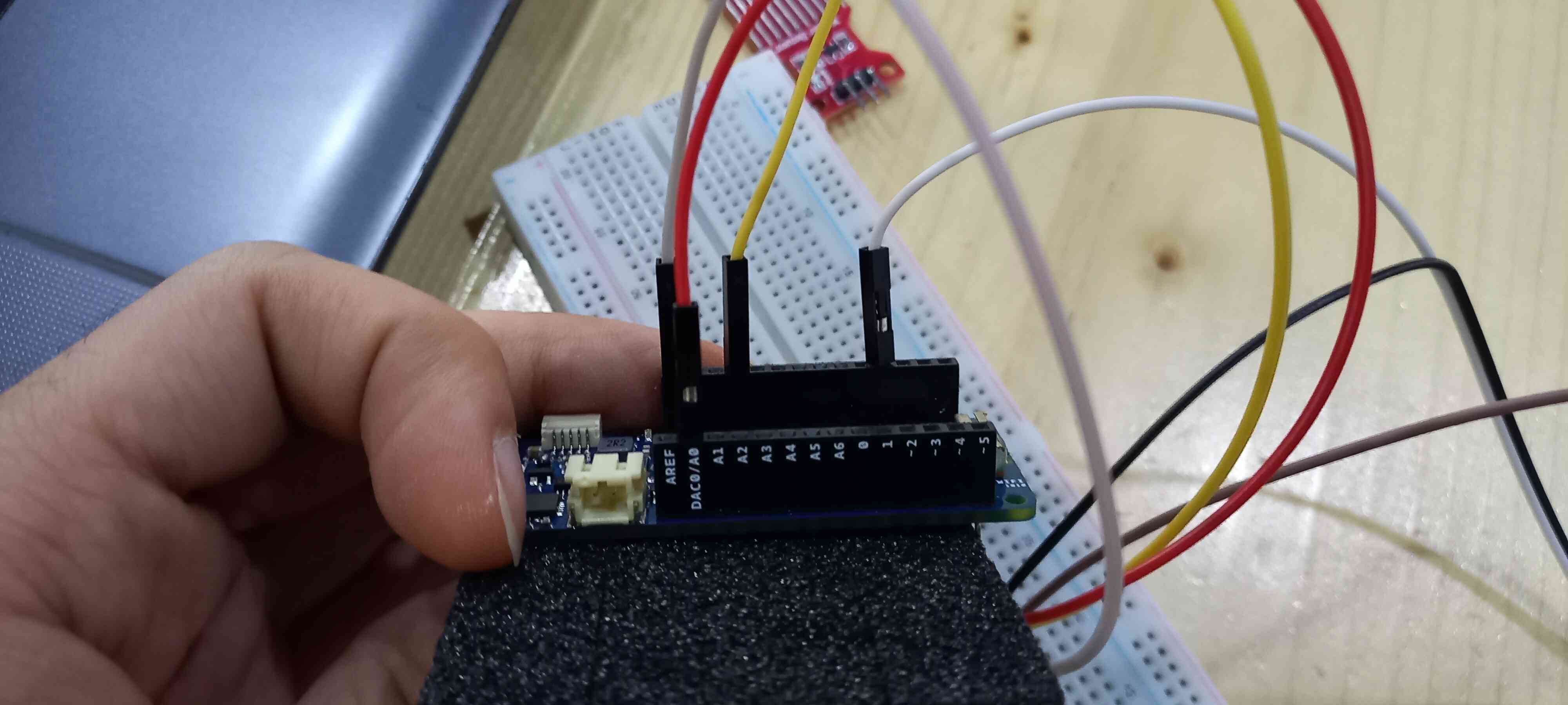
int potpin = A0; // analog pin used to connect the potentiometer
int val; // variable to read the value from the analog pin
void setup() {
myservo.attach(9); // attaches the servo on pin 9 to the servo object
Serial.begin(9600);
}
void loop() {
int sensorValue = analogRead(A0);
val = analogRead(potpin); // reads the value of the potentiometer (value between 0 and 1023)
val = map(val, 0, 1023, 0, 180); // scale it for use with the servo (value between 0 and 180)
myservo.write(val); // sets the servo position according to the scaled value
delay(15); // waits for the servo to get there
Serial.println(sensorValue);
delay(1);
}
I have added a couple of lines so that I can read the output in the serial monitor:
- In the void setup:
Serial.begin(9600);
- In the void loop
  Serial.println(sensorValue);
  delay(1);
This is a demo of the code
Task 2
In this task, I have programed the microcontroller to move a servo motor using the potentiometer, and it gives feedback in the serial monitor
- Using Proximity Sensor
/*
 Controlling a servo position using a potentiometer (variable resistor)
 by Michal Rinott <http://people.interaction-ivrea.it/m.rinott>

 modified on 8 Nov 2013
 by Scott Fitzgerald
 http://www.arduino.cc/en/Tutorial/Knob
*/

#include <Servo.h>

Servo myservo;  // create servo object to control a servo

int potpin = A0;  // analog pin used to connect the potentiometer
int val;    // variable to read the value from the analog pin

void setup() {
  myservo.attach(9);  // attaches the servo on pin 9 to the servo object
  Serial.begin(9600);
}

void loop() {
  int sensorValue = analogRead(A0);
  val = analogRead(potpin);            // reads the value of the potentiometer (value between 0 and 1023)
  val = map(val, 0, 1023, 0, 180);     // scale it for use with the servo (value between 0 and 180)
  myservo.write(val);                  // sets the servo position according to the scaled value
  delay(15);                           // waits for the servo to get there
  Serial.println(sensorValue);
  delay(1);
}
I have added a couple of lines so that I can read the output in the serial monitor:
- In the void setup:
Serial.begin(9600);
- In the void loop
  Serial.println(sensorValue);
  delay(1);
Watch this demo of the code
Using Wokwie Simulator
This is an example code to make an LED light fade
/*
  Fade

  This example shows how to fade an LED on pin 9 using the analogWrite()
  function.

  The analogWrite() function uses PWM, so if you want to change the pin you're
  using, be sure to use another PWM capable pin. On most Arduino, the PWM pins
  are identified with a "~" sign, like ~3, ~5, ~6, ~9, ~10 and ~11.

  This example code is in the public domain.

  https://www.arduino.cc/en/Tutorial/BuiltInExamples/Fade
*/

int led = 9;           // the PWM pin the LED is attached to
int brightness = 0;    // how bright the LED is
int fadeAmount = 66;    // how many points to fade the LED by

// the setup routine runs once when you press reset:
void setup() {
  // declare pin 9 to be an output:
  pinMode(led, OUTPUT);
}

// the loop routine runs over and over again forever:
void loop() {
  // set the brightness of pin 9:
  analogWrite(led, brightness);

  // change the brightness for next time through the loop:
  brightness = brightness + fadeAmount;

  // reverse the direction of the fading at the ends of the fade:
  if (brightness <= 0 || brightness >= 255) {
    fadeAmount = -fadeAmount;
  }
  // wait for 30 milliseconds to see the dimming effect
  delay(360);
}
I have changed the fade amount to 66 and the delay to 360, so that the LED fade can be more visible
Using potentiometer to drive a servo motor
/*
 Controlling a servo position using a potentiometer (variable resistor)
 by Michal Rinott <http://people.interaction-ivrea.it/m.rinott>

 modified on 8 Nov 2013
 by Scott Fitzgerald
 http://www.arduino.cc/en/Tutorial/Knob
*/

#include <Servo.h>

Servo myservo;  // create servo object to control a servo

int potpin = A0;  // analog pin used to connect the potentiometer
int val;    // variable to read the value from the analog pin

void setup() {
  myservo.attach(9);  // attaches the servo on pin 9 to the servo object
  Serial.begin(9600);
}

void loop() {
  int sensorValue = analogRead(A0);
  val = analogRead(potpin);            // reads the value of the potentiometer (value between 0 and 1023)
  val = map(val, 0, 1023, 0, 180);     // scale it for use with the servo (value between 0 and 180)
  myservo.write(val);                  // sets the servo position according to the scaled value
  delay(15);                           // waits for the servo to get there
  Serial.println(sensorValue);
  delay(1);
}
I have added a couple of lines so that I can read the output in the serial monitor:
- In the void setup:
Serial.begin(9600);
- In the void loop
  Serial.println(sensorValue);
  delay(1);
Group Assignment
Check out Sami’s documentation for our group assignment
Final Thoughts
Using Input/Output devices helped me understand how I can basically use sensors to give input to the microcontroller, which in return gives the information to the output device (in my case it is a servo motor) that diplays/moves according to the information given.