4. Embedded programming
In this assignment, I have worked on Arduino boards and programming softwares.
What is a microcontroller?
A microcontroller is basically a small integrated circuit designed to operate a specific operation in an embedded system.
Microcontrollers consists of:
- Processor
- Memory
- Input/Output (I/O) peripherals.
Softwares
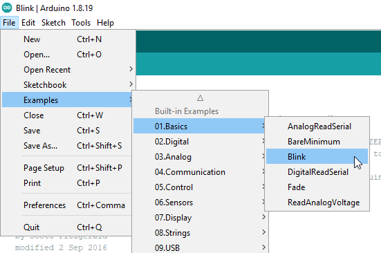
To program the Arduino microcontroller, use the Arduino IDE software
Arduino IDE
After downloading the software and after learning basic information about the boards, I have started working on programming the boards to run basic commands/functions.
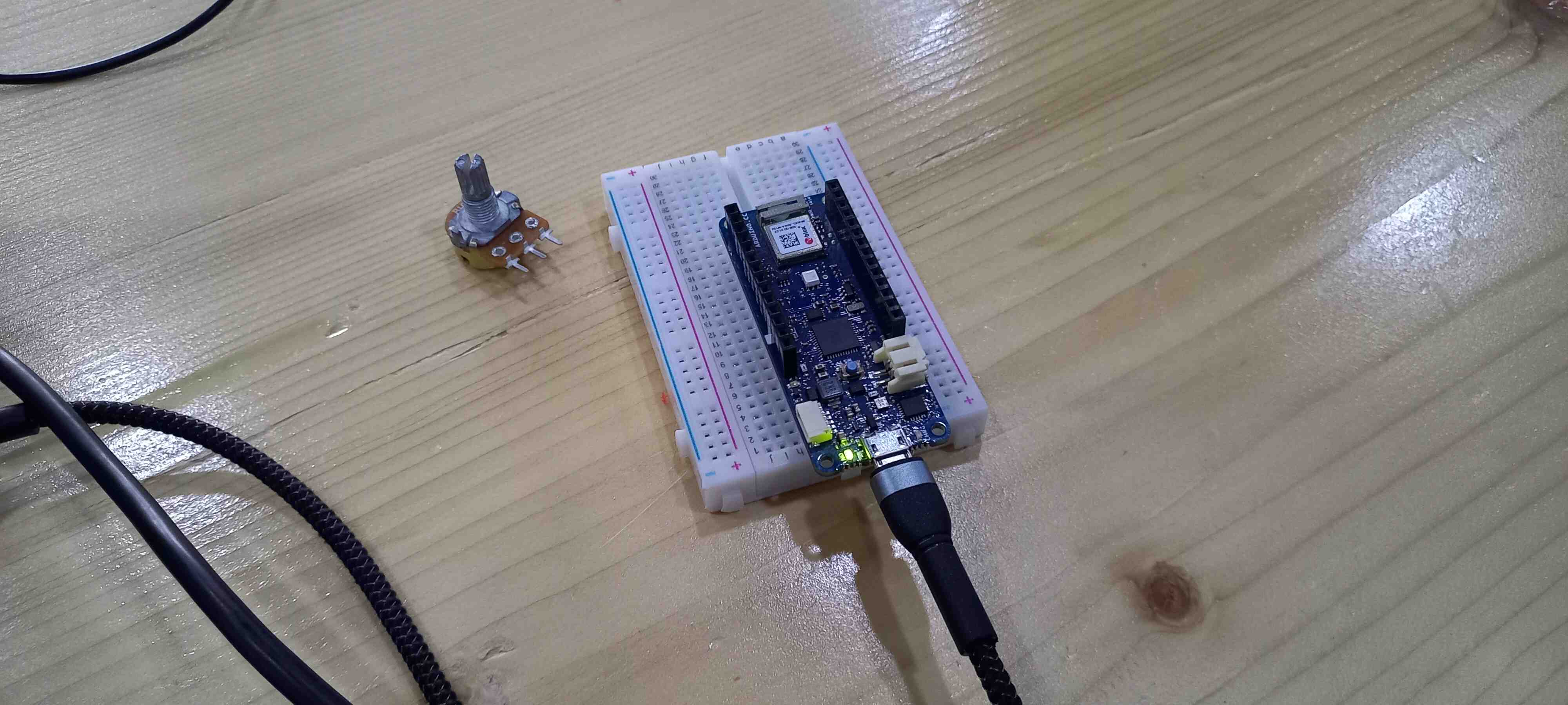
Before proceeding with the tasks, first connect the Arduino with your laptop/desktop via a USB cable
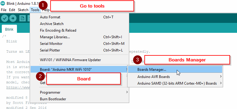
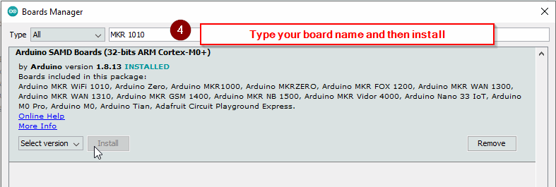
First, download your board driver
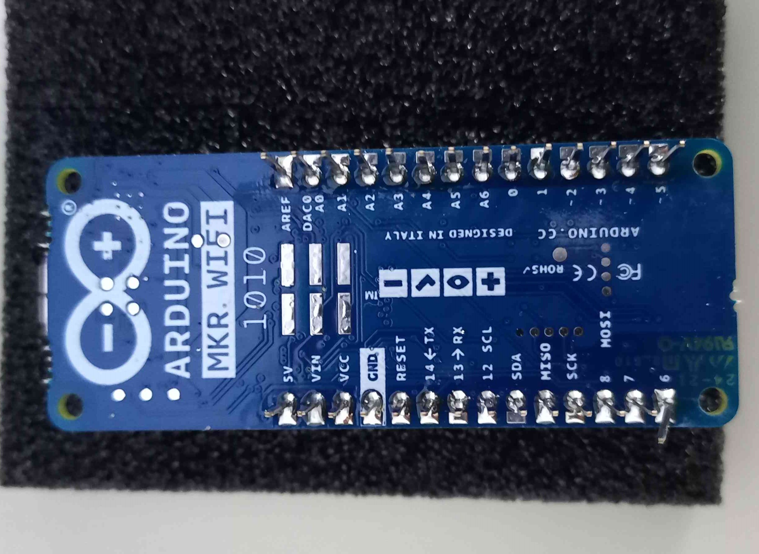
I used Arduino MKR WIFI 1010 board
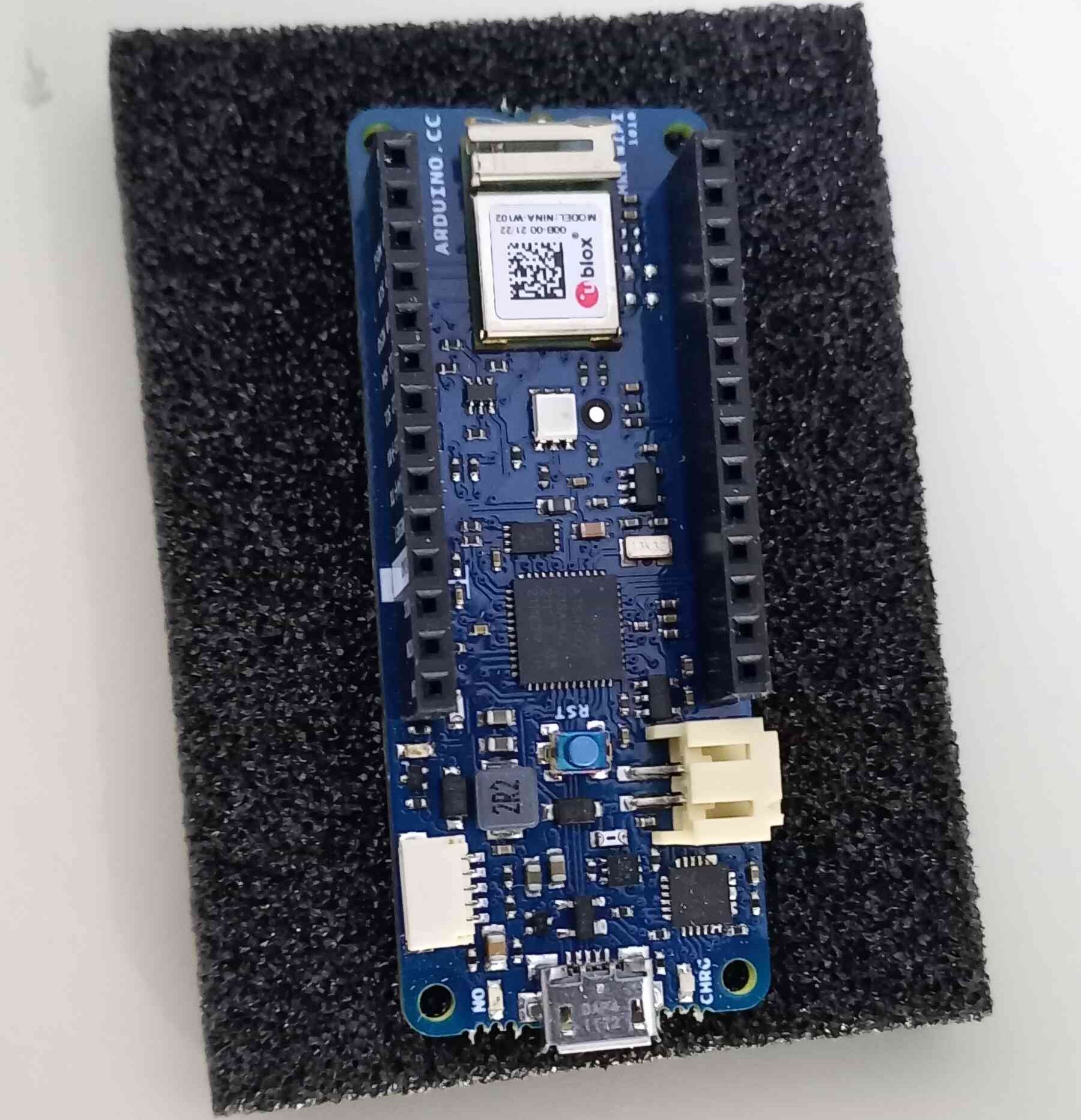
Then connect it via a USB cable
These are the functions and descriptions of the board pins:
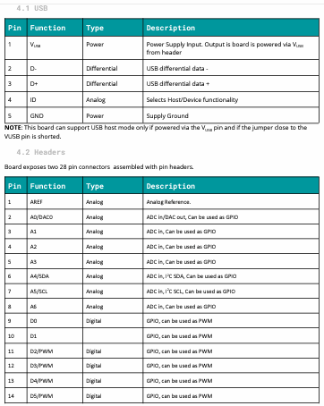
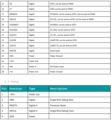
View the Arduino MKR WIFI 1010 Datasheet for more info.
When reading the microcontroller datasheet, notice that the pins are divided between analog (A0 to A6) and digital (~0 to ~14) pins, which means that the microcontroller can convert between digital and analog.
Analog pins helps the user to read voltage levels (sensor values) in a continuous manner (Between 0 to 1023), while digital pins responses with 0 or 1 (In binary)
Task 1
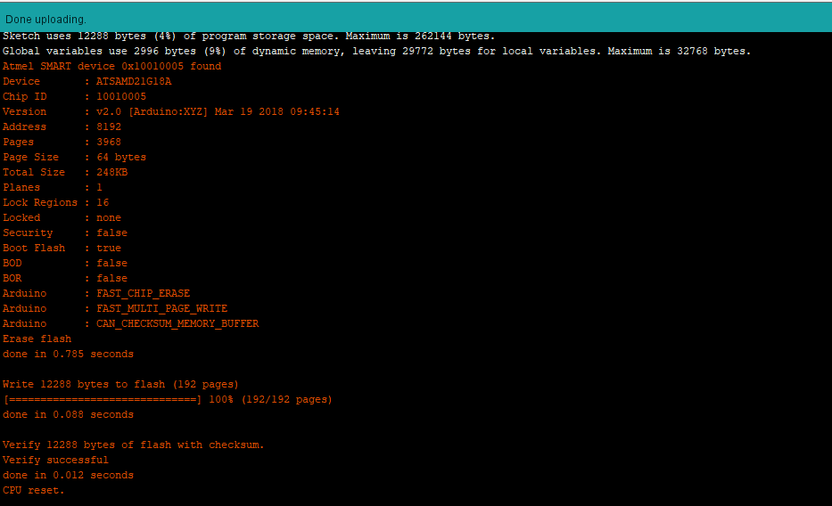
In this task, the objective is to make the microcontroller LED light blink.
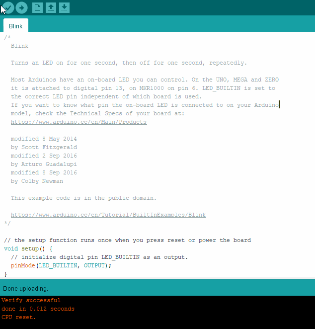

/*
  Blink

  Turns an LED on for one second, then off for one second, repeatedly.

  Most Arduinos have an on-board LED you can control. On the UNO, MEGA and ZERO
  it is attached to digital pin 13, on MKR1000 on pin 6. LED_BUILTIN is set to
  the correct LED pin independent of which board is used.
  If you want to know what pin the on-board LED is connected to on your Arduino
  model, check the Technical Specs of your board at:
  https://www.arduino.cc/en/Main/Products

  modified 8 May 2014
  by Scott Fitzgerald
  modified 2 Sep 2016
  by Arturo Guadalupi
  modified 8 Sep 2016
  by Colby Newman

  This example code is in the public domain.

  https://www.arduino.cc/en/Tutorial/BuiltInExamples/Blink
*/

// the setup function runs once when you press reset or power the board
void setup() {
  // initialize digital pin LED_BUILTIN as an output.
  pinMode(LED_BUILTIN, OUTPUT);
}

// the loop function runs over and over again forever
void loop() {
  digitalWrite(LED_BUILTIN, HIGH);   // turn the LED on (HIGH is the voltage level)
  delay(1000);                       // wait for a second
  digitalWrite(LED_BUILTIN, LOW);    // turn the LED off by making the voltage LOW
  delay(1000);                       // wait for a second
}
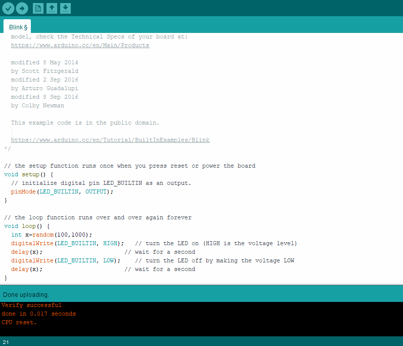
Task 2
In this task, the objective is to make the microcontroller LED light blink randomly.
// the setup function runs once when you press reset or power the board
void setup() {
  // initialize digital pin LED_BUILTIN as an output.
  pinMode(LED_BUILTIN, OUTPUT);
}

// the loop function runs over and over again forever
void loop() {
  int x=random(100,1000)
  digitalWrite(LED_BUILTIN, HIGH);   // turn the LED on (HIGH is the voltage level)
  delay(x);                       // wait for a second
  digitalWrite(LED_BUILTIN, LOW);    // turn the LED off by making the voltage LOW
  delay(x);                       // wait for a second
}
Task 3
In this task, the objective is to make the LED light blink in Morse code.
I have choose to use the word “Fablab” to be displayed as Morse code.
// the setup function runs once when you press reset or power the board
void setup() {
  // initialize digital pin LED_BUILTIN as an output.
  pinMode(LED_BUILTIN, OUTPUT);
}

//The word is Fablab in Morse code
// the loop function runs over and over again forever
void loop() {
  int dot=500;
  int dash=1500;
  int space=500;
  int between=2500;
  digitalWrite(LED_BUILTIN, HIGH);   // turn the LED on (HIGH is the voltage level)
  delay(dot);                       // wait for a second
  digitalWrite(LED_BUILTIN, HIGH);   // turn the LED on (HIGH is the voltage level)
  delay(dot);                       // wait for a second
  digitalWrite(LED_BUILTIN, HIGH);   // turn the LED on (HIGH is the voltage level)
  delay(dash);
  digitalWrite(LED_BUILTIN, HIGH);   // turn the LED on (HIGH is the voltage level)
  delay(dot);

  digitalWrite(LED_BUILTIN, LOW);    // turn the LED off by making the voltage LOW
  delay(space);                       // wait for a second

  digitalWrite(LED_BUILTIN, HIGH);   // turn the LED on (HIGH is the voltage level)
  delay(dot);
    digitalWrite(LED_BUILTIN, HIGH);   // turn the LED on (HIGH is the voltage level)
  delay(dash);

    digitalWrite(LED_BUILTIN, LOW);    // turn the LED off by making the voltage LOW
  delay(space);

   digitalWrite(LED_BUILTIN, HIGH);   // turn the LED on (HIGH is the voltage level)
  delay(dash);
  digitalWrite(LED_BUILTIN, HIGH);   // turn the LED on (HIGH is the voltage level)
  delay(dot);                       // wait for a second
  digitalWrite(LED_BUILTIN, HIGH);   // turn the LED on (HIGH is the voltage level)
  delay(dot);
    digitalWrite(LED_BUILTIN, HIGH);   // turn the LED on (HIGH is the voltage level)
  delay(dot);

      digitalWrite(LED_BUILTIN, LOW);    // turn the LED off by making the voltage LOW
  delay(space);

   digitalWrite(LED_BUILTIN, HIGH);   // turn the LED on (HIGH is the voltage level)
  delay(dot);
    digitalWrite(LED_BUILTIN, HIGH);   // turn the LED on (HIGH is the voltage level)
  delay(dash);


    digitalWrite(LED_BUILTIN, LOW);    // turn the LED off by making the voltage LOW
  delay(space);

     digitalWrite(LED_BUILTIN, HIGH);   // turn the LED on (HIGH is the voltage level)
  delay(dash);
  digitalWrite(LED_BUILTIN, HIGH);   // turn the LED on (HIGH is the voltage level)
  delay(dot);                       // wait for a second
  digitalWrite(LED_BUILTIN, HIGH);   // turn the LED on (HIGH is the voltage level)
  delay(dot);
    digitalWrite(LED_BUILTIN, HIGH);   // turn the LED on (HIGH is the voltage level)
  delay(dot);

      digitalWrite(LED_BUILTIN, LOW);    // turn the LED off by making the voltage LOW
  delay(between);
}
Task 4
In this task, the objective is to write a name or a sentence in the serial monitor and the led will blink in morse code corresponding to the letters
int incomingByte = 0; // for incoming serial data

void setup() {
  Serial.begin(9600); // opens serial port, sets data rate to 9600 bps
  Serial.println("ready");
}

  int dot=500;
  int dash=1500;
  int space=500;
  int between=2500;


void doot() {
  digitalWrite(LED_BUILTIN, HIGH);
  delay(dot);
    digitalWrite(LED_BUILTIN, LOW);

}

void daash() {
    digitalWrite(LED_BUILTIN, HIGH);
  delay(dash);
   digitalWrite(LED_BUILTIN, LOW);
}

void spaace() {
    digitalWrite(LED_BUILTIN, LOW);
  delay(space);
   digitalWrite(LED_BUILTIN, LOW);
}

void betwen() {
        digitalWrite(LED_BUILTIN, LOW);
  delay(between);
   digitalWrite(LED_BUILTIN, LOW);
}

void loop() {
  switch(incomingByte) {
    case 'a':
    doot();
    spaace();
    daash();
    spaace();
    break;
    case 'b':
    daash();
    spaace();
    doot();
    spaace();
    doot();
    spaace();
    doot();
    spaace();
    break;
    case 'c':
    daash();
    spaace();
    doot();
    spaace();
    daash();
    spaace();
    doot();
    spaace();
    break;
    case 'd':
    daash();
    spaace();
    daash();
    spaace();
    doot();
    spaace();
    break;
    case 'e':
    doot();
    spaace();
    break;
    case 'f':
    doot();
    spaace();
    doot();
    spaace();
    daash();
    spaace();
    doot();
    spaace();
    break;
    case 'g':
    daash();
    spaace();
    daash();
    spaace();
    doot();
    spaace();
    break;
    case 'h':
    daash();
    spaace();
    daash();
    spaace();
    doot();
    spaace();
    doot();
    spaace();
    break;
    case 'i':
    doot();
    spaace();
    doot();
    spaace();
    break;
    case 'j':
    doot();
    spaace();
    daash();
    spaace();
    daash();
    spaace();
    daash();
    spaace();
    break;
      case 'k':
    daash();
    spaace();
    doot();
    spaace();
    daash();
    spaace();
    break;
    case 'l':
    doot();
    spaace();
    daash();
    spaace();
    doot();
    spaace();
    doot();
    spaace();
    break;
      case 'm':
    daash();
    spaace();
    daash();
    spaace();
    break;
    case 'n':
    daash();
    spaace();
    doot();
    spaace();
    break;
    case 'o':
    daash();
    spaace();
    daash();
    spaace();
    daash();
    spaace();
    break;
    case 'p':
    doot();
    spaace();
    daash();
    spaace();
    daash();
    spaace();
    doot();
    spaace();
    break;
    case 'q':
    daash();
    spaace();
    daash();
    spaace();
    doot();
    spaace();
    daash();
    spaace();
    break;
    case 'r':
     doot();
    spaace();
    daash();
    spaace();
    doot();
    spaace();
    break;
    case 's':
    doot();
    spaace();
    doot();
    spaace();
    doot();
    spaace();
    break;
    case 't':
    daash();
    spaace();
    break;
    case 'u':
    doot();
    spaace();
    doot();
    spaace();
    daash();
    spaace();
    break;
    case 'v':
    doot();
    spaace();
    doot();
    spaace();
    doot();
    spaace();
    daash();
    spaace();
    break;
    case 'w':
    doot();
    spaace();
    daash();
    spaace();
    daash();
    spaace();
    break;
    case 'x':
    daash();
    spaace();
    doot();
    spaace();
    doot();
    spaace();
    daash();
    spaace();
    break;
    case 'y':
    daash();
    spaace();
    doot();
    spaace();
    daash();
    spaace();
    daash();
    spaace();
    break;
    case 'z':
    daash();
    spaace();
    daash();
    spaace();
    doot();
    spaace();
    doot();
    spaace();
    break;
  }

  // send data only when you receive data:
  if (Serial.available() > 0) {
    // read the incoming byte:
    incomingByte = Serial.read();

    // say what you got:
    Serial.print("I received: ");
    Serial.println(incomingByte, DEC);
  }
}
This is a demonstration of the code
Wokwi simulator
This is a website used for Arduino simulations, here is an example of the code in task 4
I have used wokwi.com simulator
Final Thoughts
When I hear the word electronics I cannot help but imagine long strips of wires, resistors and other devices, but when I started working on the Arduino microcontrollers, that thought gradually faded away because of how simple it is to program and use.