7. Input & Output device
what is input and output ?
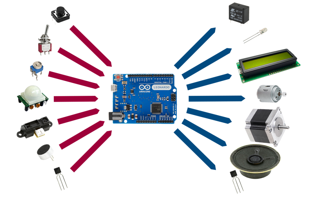
input
An input device sends information to a computer system for processing, and an output device reproduces or displays the results of that processing. Input devices only allow for input of data to a computer and output devices only receive the output of data from another device.
input example
- Keyboard and Mouse
Accepts input from a user and sends that data (input) to the computer. They cannot accept or reproduce information (output) from the computer.
- Microphone
Receives sound generated by an input source, and sends that sound to a computer.
- Webcam
Receives images generated by whatever it is pointed at (input) and sends those images to a computer.
output
An output device can receive data from another device and generate output with that data, but it cannot send data to another device. Examples of output devices include the following.
output example
- Monitor
Receives data from a computer (output) and displays that information as text and images for users to view. It cannot accept data from a user and send that data to another device. - Projector
Receives data from a computer (output) and displays, or projects, that information as text and images onto a surface, like a wall or screen. It cannot accept data from a user and send that data to another device. - Speakers
Receives sound data from a computer and plays the sounds for users to hear. It cannot accept sound generated by users and send that sound to another device.
INDIVIDUAL ASSIGNMENT:
project 1
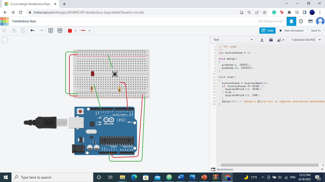
buttons and LED
the project is to light the LED light when press the button
 the connection
using a Arduino LED LIGHT Button and 2 resistor’s
// C++ code
//
int buttonState = 0;

void setup()
{
  pinMode(2, INPUT);
  pinMode(13, OUTPUT);
}

void loop()
{
  buttonState = digitalRead(2);
  if (buttonState == HIGH) {
    digitalWrite(13, HIGH);
  } else {
    digitalWrite(13, LOW);
  }
  delay(10); // Delay a little bit to improve simulation performance
}
and it went successfully
project 2 (Challenge)
Our instructor have asked us to do one of the following tasks from below:
EASY MODE: Use the one of the sensors on the Adafruit & try to program to display its results in the serial monitor + to be represented by an LED &/or Buzzer
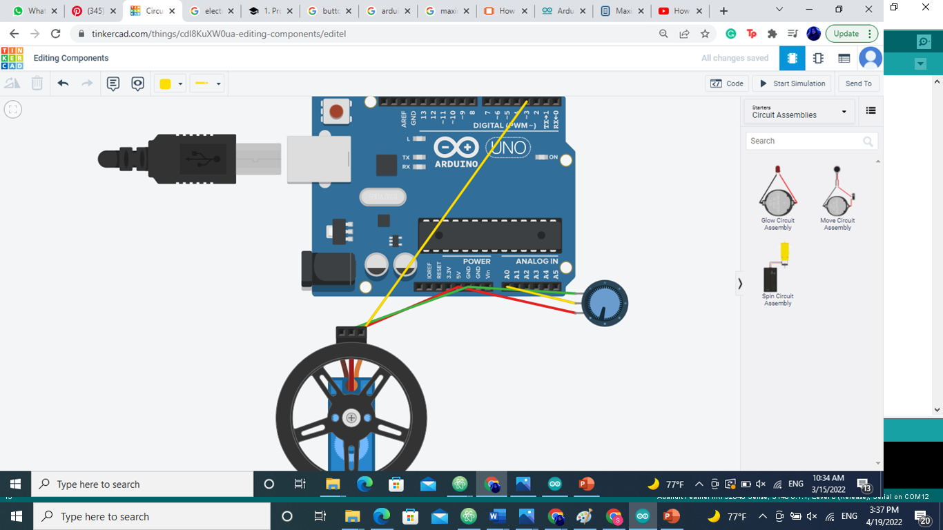
MEDIUM MODE: Use a variable resistor as an input to to control either the speed or the direction of the servo motor.
HARD MODE: Try to create a small automated farming system using the light sensor & the servor motor. Where it’s according to sun day the plant start be filling by the water.
EXTREME MODE: Create a cooling system using a fan, variable resistor, Temperature sensor & an LCD. The idea is to control the fan automatic & manually. You can adjust the fan coolness automatically using the temperature sensor to increase or decrease the fan rotation and display its on the LCD. Or switching the to manual mode where you rotate the variable resistor according to how fast you want the fan to go and it should be display on the LCD screen.
Circuit I choose the medium mode Servo motors have three wires: power, ground, and signal. The power wire is typically red, and should be connected to the 5V pin on the Arduino board. The ground wire is typically black or brown and should be connected to a ground pin on the board. The signal pin is typically yellow or orange and should be connected to PWM pin on the board. In these examples, it is pin number 3.
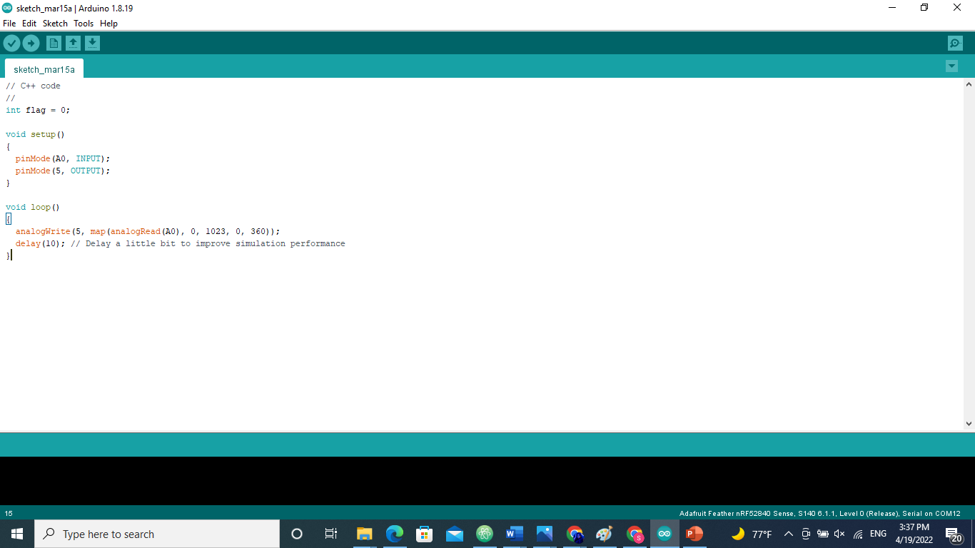
the code
// C++ code
//
int flag = 0;

void setup()
{
  pinMode(A0, INPUT);
  pinMode(5, OUTPUT);
}

void loop()
{
  analogWrite(5, map(analogRead(A0), 0, 1023, 0, 360));
  delay(10); // Delay a little bit to improve simulation performance
}