4. Embedded programming
group assignment
other croup assignment
Different types of microcontrollers boards and comparison between them Qassim Nader website
individual assignment
data sheet
its a applymantation of the coding on a microcontroller is a to control the output and input by coding and there is a many type of the microcontroller such Arduino and adafruit . Adafruit Feather nRF52840 Sense is make a wirelass sensor platform and with bluetooth low energy and a USB support and its all in one arduino-compatible Bluetooth low energy built in USB plus battery chargeing With native USB
1 -Microcontroller and QSPI
Nordic nRF52840 Bluetooth LE processor - 1 MB of Flash, 256KB RAM, 64 MHz Cortex M4 processor. QSPI flash - 2MB of internal flash storage for datalogging or CircuitPython code. QSPI requires 6 pins, which are not broken out on the 0.1” pin headers to avoid conflicts. QSPI is neat because it allows you to have 4 data in/out lines instead of just SPI’s single line in and single line out. This means that QSPI is at least 4 times faster. But in reality is at least 10x faster because you can clock the QSPI peripheral much faster than a plain SPI peripheral.
2 - Power Pins A - 3V: This pin is connected to the output of the on board 3.3V regulator. It can be used to supply 3.3V power to external sensors, breakouts or FeatherWings.
B - LIPO Input (Bat): This is the voltage supply off the optional LIPO cell that can be connected via the JST PH connector. It is nominally ~3.5-4.2V.
C - VREG Enable (En): This pin can be set to GND to disable the 3.3V output from the on board voltage regulator. By default it is set high via a pullup resistor.
D - USB Power (USB): This is the voltage supply off USB connector, nominally 4.5-5.2V.
3 - Analog Pins
A - analog inputs: The 6 available analog inputs (A0 .. A5) can be configured to generate 8, 10 or 12-bit data (or 14-bits with over-sampling), at speeds up to 200kHz (depending on the bitwidth of the values generated), based on either an internal 0.6V reference or the external supply.
B - AREF (A7 / P0.31): which can be used as an optional external analog reference for the internal comparator (COMP) peripheral. AREF is not available for use with the ADC. This pin can be accessed in code via PIN_AREF or A7. If using an external AREF, this must be less than or equal to VDD, which is usually 3.3V!
PWM Outputs and I2C Pins
A - I2C Pins I2C pins on the nRF52840 have 4.7K pullup resistors installed and are connected to all-but-the-microphone sensors. You can connect any other sensors as long as there is not an I2C address collision
B - D2/NFC2: The D2 pin is uses the same pad as one-half of the NFC antenna pins.
Sensors
A - Gyro + Accel: This sensor is a 6-DoF IMU accelerometer + gyroscope. The 3-axis accelerometer, can tell you which direction is down towards the Earth (by measuring gravity) or how fast the Feather Sense is accelerating in 3D space
B - Magnetometer: Sense the magnetic fields that surround us with this handy triple-axis magnetometer (compass) module. Magnetometers can sense where the strongest magnetic force is coming from, generally used to detect magnetic north, but can also be used for measuring magnetic fields
C - Light + Gesture + Proximity: Detect simple gestures (left to right, right to left, up to down, down to up are currently supported), return the amount of red, blue, green, and clear light, or return how close an object is to the front of the sensor. This ©Adafruit Industries Page 18 of 188 sensor has an integrated IR LED and driver, along with four directional photodiodes that sense reflected IR energy from the LED. Since there are four IR sensors, you can measure the changes in light reflectance at each of the cardinal locations over time and turn those changes into gestures. Sensor is I2C on standard pins, address 0x39 and IRQ pin on digital pin 36
D - Humidity: This sensor has an excellent ±2% relative humidity and ±0.5°C accuracy for most uses. Sensor is I2C on standard pins, address 0x44 E - Temp + Pressure: This sensor is a precision sensing solution for measuring barometric pressure with ±1 hPa absolute accuracy, and temperature with ±1.0°C ©Adafruit Industries Page 19 of 188
F - PDM Microphone sound sensor: MP34DT01-M - PDM sound sensor. In CircuitPython, board.MICROPHONE_DATA is PDM data, and board.MICROPHONE_CLOCK is PDM clock. In Arduino, D34 is PDM data, and D35 is PDM clock
USB and Battery
A - USB Micro: This USB port is used for programming and/or powering the Feather Sense. It is a standard USB Micro connector.
B- Battery : 2-pin JST PH connector for a battery. Power the Feather Sense from any 3V-6V power source, as it has internal regulator and protection diodes. You can also charge LiPoly batteries plugged into this connector using USB power.
Buttons
Reset button - The button on the left next to the USB connector resets the board. Press once to reset. Quickly press twice to enter the bootloader. User button - The button on the right is both usable by the bootloader and usercontrollable. Address it in code using board.SWITCH in CircuitPython and D7 in Arduino
NeoPixel and Status LEDs
NeoPixel - The addressable RGB NeoPixel LED is used as a status LED by the bootloader and CircuitPython, but is also controllable using code. Control it using board.NEOPIXEL in CircuitPython and D8 in Arduino.
Red status LED - This little red LED, labeled D13, works as a status LED in the bootloader. Otherwise, it is controllable using code by addressing board.RED_L ED in CircuitPython, and D13 in Arduino.
Blue status LED - This little blue LED, labeled Conn, works as a connectivity status LED in Arduino, and is user-controllable in both Arduino and CircuitPython. Control it in code by addressing board.BLUE_LED in CircuitPython and D4 in Arduino.
Charge status LED - The little LED, labeled CHG, below the USB connector is the charge status LED. When no battery is connected, it flashes. When a battery is connected and charging, the LED is steady amber. •
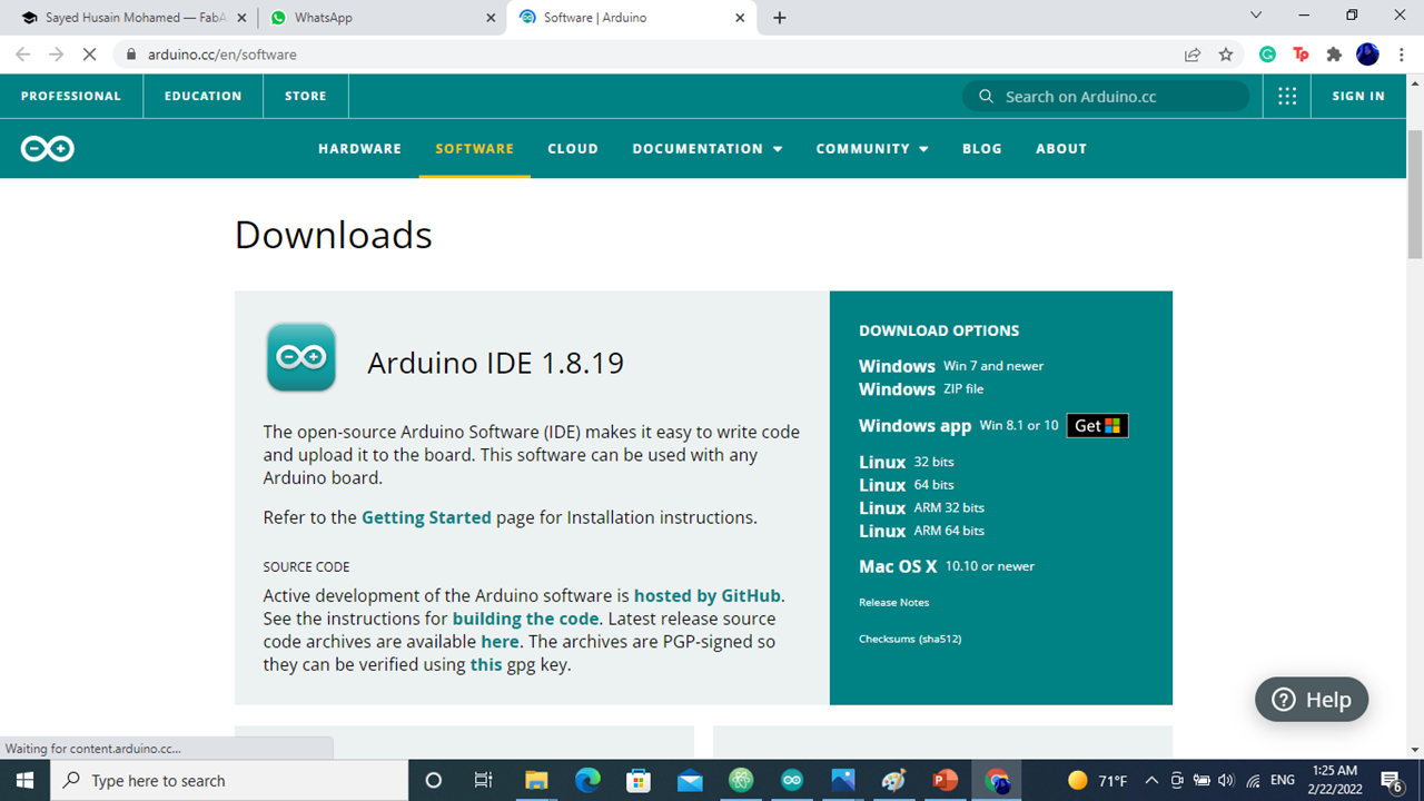 downlead Arduino
The is it open-source Arduino Software (IDE) makes it easy to write code and upload it to the board. This software can be used with any Arduino board.
downlead Arduino
The is it open-source Arduino Software (IDE) makes it easy to write code and upload it to the board. This software can be used with any Arduino board.
downlead library
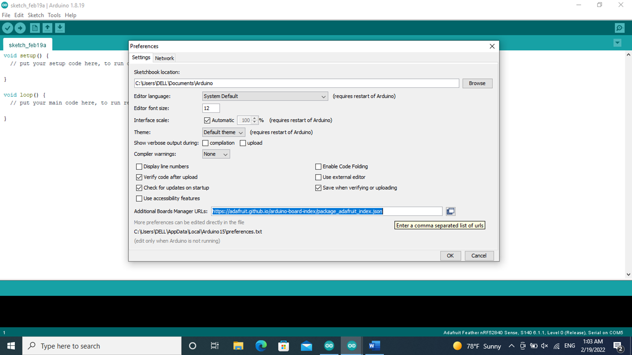
the link for the library https://adafruit.github.io/arduino-board-index/package_adafruit_index.json
 go to the board manager to downlead it
 find the library and install it
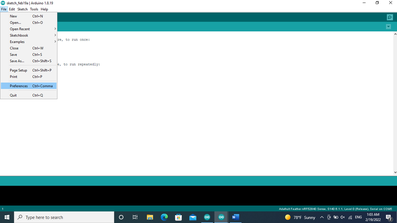
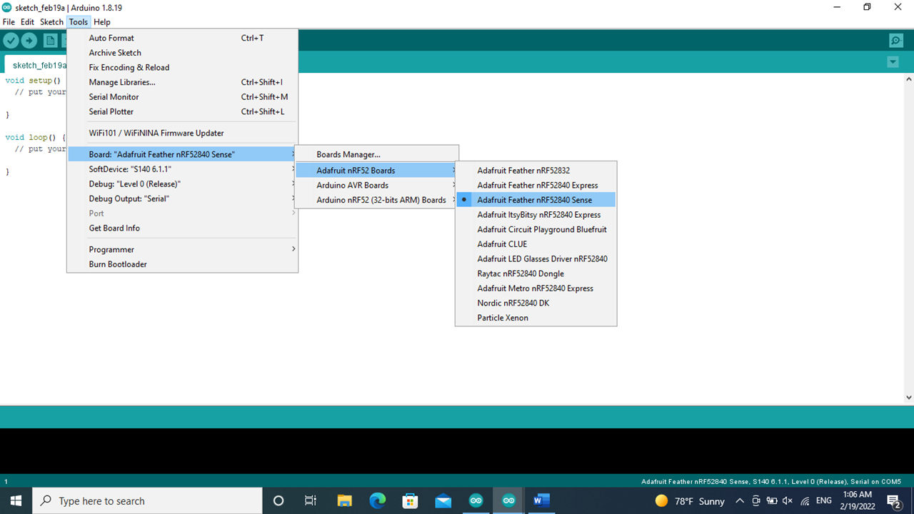 make sure of the board language This steps to set a languages to get it understand between the application and the microcontroller
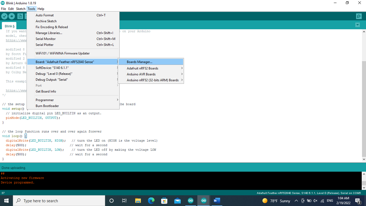
 choose the controller from the port
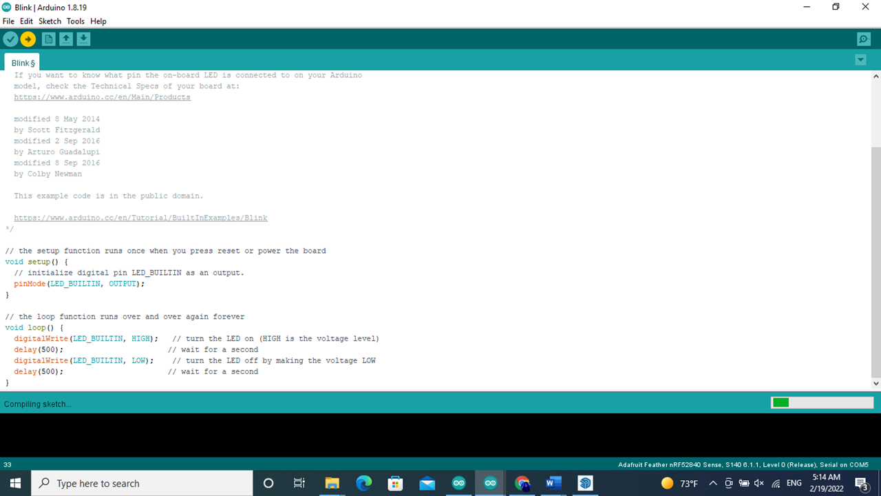
 for example we want to choose the and we want to choose blink To try the microcontroller follow the steps to start the light to blink
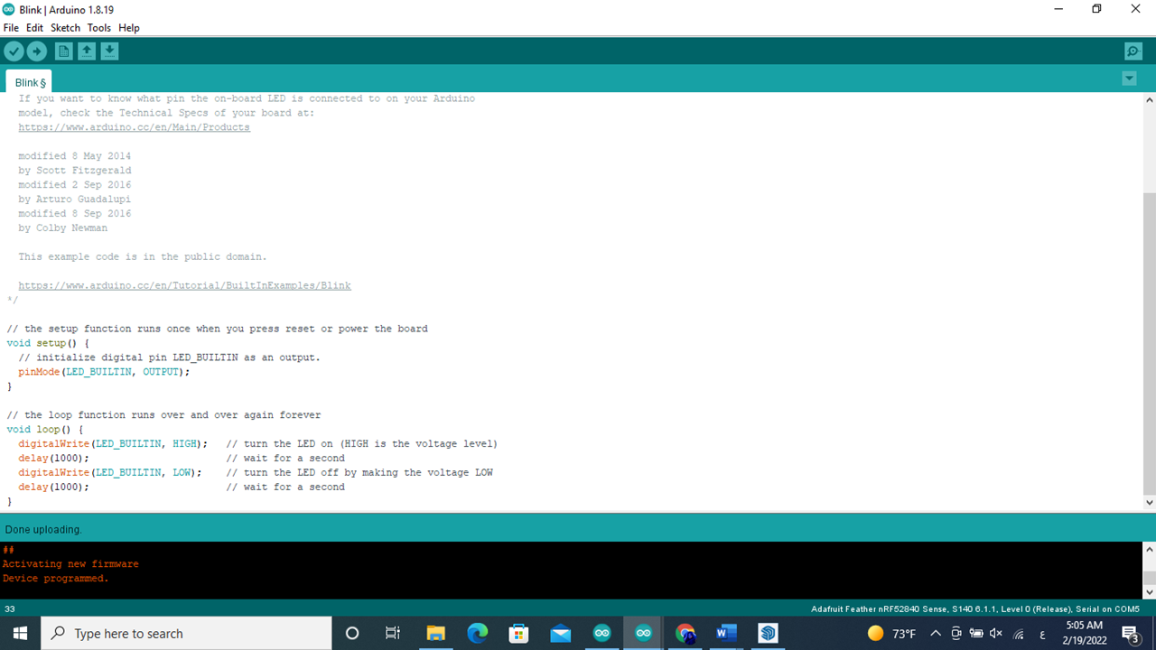 it will open a code that control the LED light
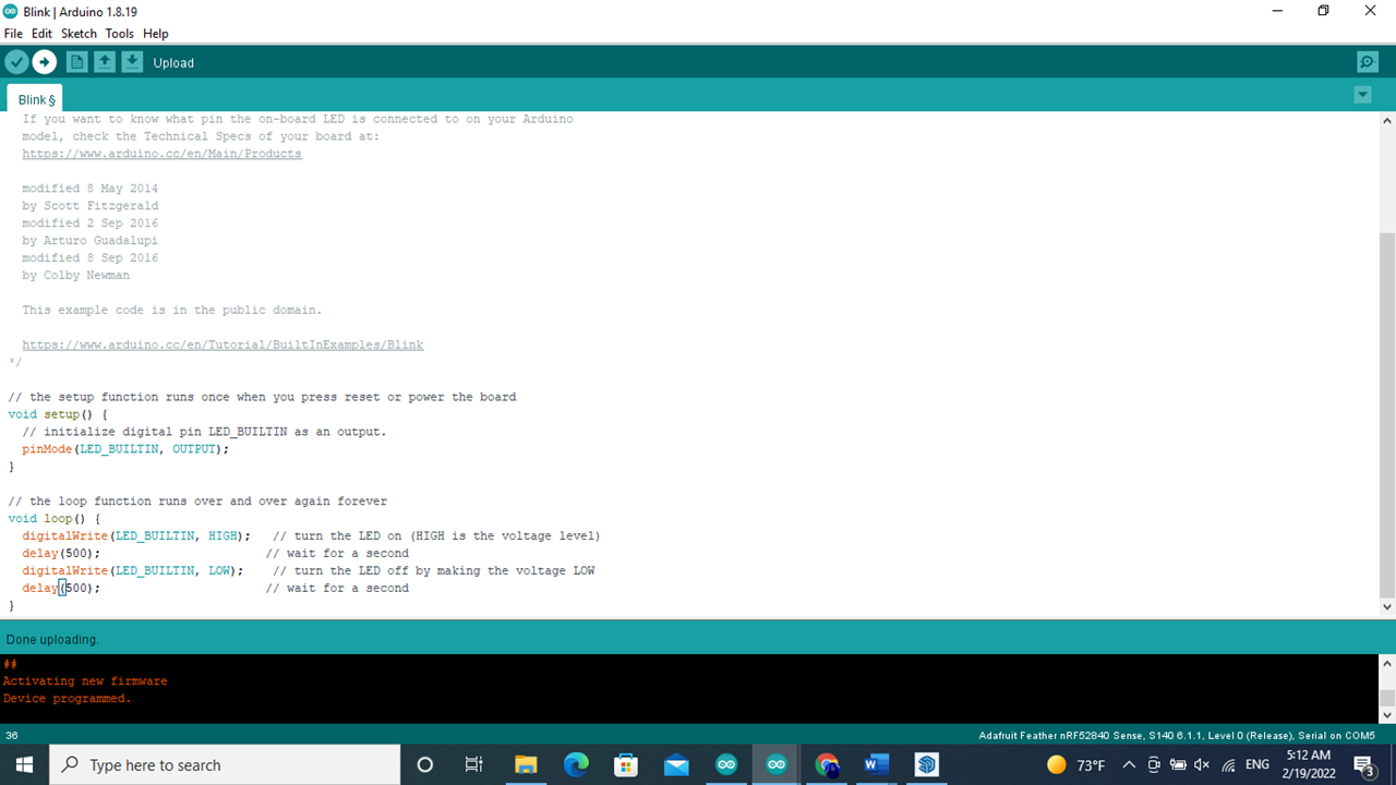
the number beside the delay(1000); is number of the microsecend that will have 1000 ms on and 1000 ms and any number will change the bilink will change // the loop function runs over and over again forever void loop() { digitalWrite(LED_BUILTIN, HIGH); // turn the LED on (HIGH is the voltage level) delay(1000); // wait for a second digitalWrite(LED_BUILTIN, LOW); // turn the LED off by making the voltage LOW delay(1000); // wait for a second

TINKERCAD
 sign up in the wibsite
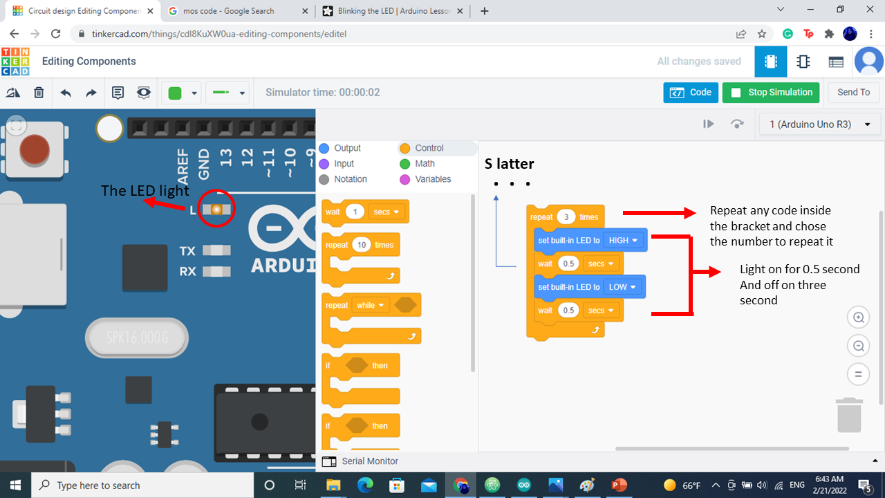
 the block coding is combination between output , control , input , math and other
firs we chose the Output and each bottom mean the on and off of the LED light
the block coding is combination between output , control , input , math and other
firs we chose the Output and each bottom mean the on and off of the LED light
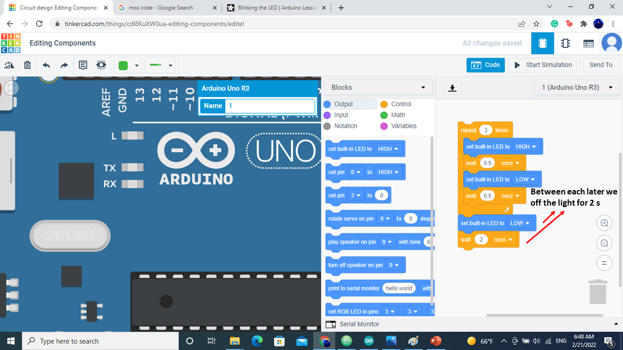
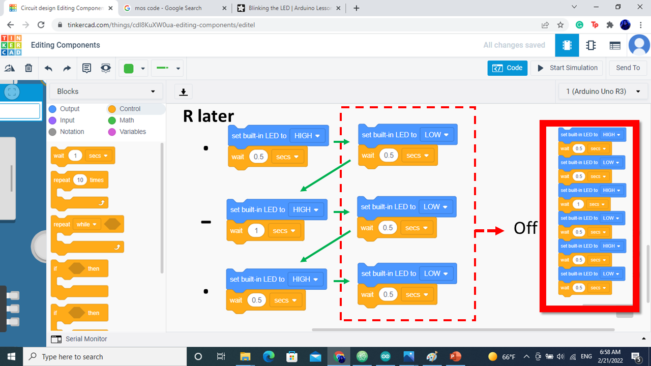
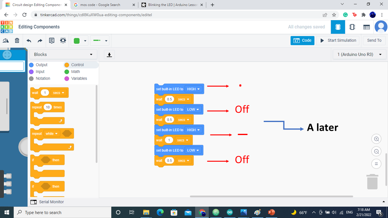
I start to write my name in Morse code


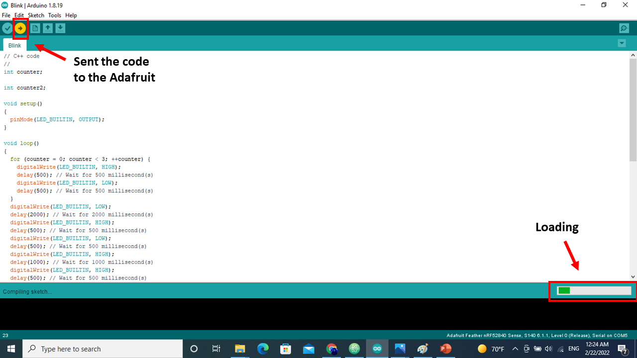
// C++ code
//
int counter;

int counter2;

void setup()
{
  pinMode(LED_BUILTIN, OUTPUT);
}

void loop()
{
  for (counter = 0; counter < 3; ++counter) {
    digitalWrite(LED_BUILTIN, HIGH);
    delay(500); // Wait for 500 millisecond(s)
    digitalWrite(LED_BUILTIN, LOW);
    delay(500); // Wait for 500 millisecond(s)
  }
  digitalWrite(LED_BUILTIN, LOW);
  delay(2000); // Wait for 2000 millisecond(s)
  digitalWrite(LED_BUILTIN, HIGH);
  delay(500); // Wait for 500 millisecond(s)
  digitalWrite(LED_BUILTIN, LOW);
  delay(500); // Wait for 500 millisecond(s)
  digitalWrite(LED_BUILTIN, HIGH);
  delay(1000); // Wait for 1000 millisecond(s)
  digitalWrite(LED_BUILTIN, HIGH);
  delay(500); // Wait for 500 millisecond(s)
  digitalWrite(LED_BUILTIN, LOW);
  delay(2000); // Wait for 2000 millisecond(s)
  digitalWrite(LED_BUILTIN, HIGH);
  delay(500); // Wait for 500 millisecond(s)
  digitalWrite(LED_BUILTIN, LOW);
  delay(500); // Wait for 500 millisecond(s)
  digitalWrite(LED_BUILTIN, HIGH);
  delay(1000); // Wait for 1000 millisecond(s)
  digitalWrite(LED_BUILTIN, LOW);
  delay(500); // Wait for 500 millisecond(s)
  digitalWrite(LED_BUILTIN, HIGH);
  delay(500); // Wait for 500 millisecond(s)
  digitalWrite(LED_BUILTIN, LOW);
  delay(2000); // Wait for 2000 millisecond(s)
  digitalWrite(LED_BUILTIN, HIGH);
  delay(500); // Wait for 500 millisecond(s)
  digitalWrite(LED_BUILTIN, LOW);
  delay(500); // Wait for 500 millisecond(s)
  digitalWrite(LED_BUILTIN, HIGH);
  delay(1000); // Wait for 1000 millisecond(s)
  digitalWrite(LED_BUILTIN, LOW);
  delay(2000); // Wait for 2000 millisecond(s)
  for (counter2 = 0; counter2 < 4; ++counter2) {
    digitalWrite(LED_BUILTIN, HIGH);
    delay(500); // Wait for 500 millisecond(s)
    digitalWrite(LED_BUILTIN, LOW);
    delay(500); // Wait for 500 millisecond(s)
  }
  digitalWrite(LED_BUILTIN, LOW);
  delay(2000); // Wait for 2000 millisecond(s)
}