4. Embedded programming
This week I worked on embedded programming, learned more about microcontrollers and how they work.
Microcontrollers
A microcontroller is a single integrated circuit that comprises various elements, including a microprocessor, timers, counters, input/output (I/O) ports, random access memory (RAM), read-only memory (ROM), and some other components. These parts work together to execute a pre-programmed set of specific tasks. Thus, a microcontroller is like a little computer that processes and even executes control in an electronic device.
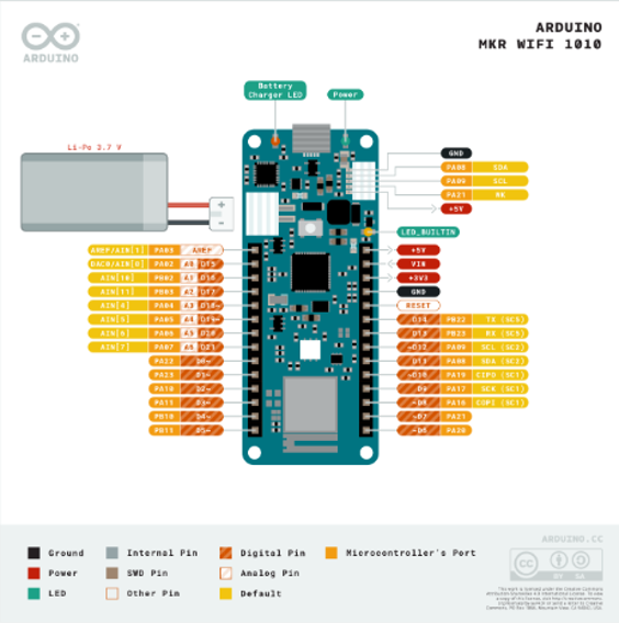
MkR1010 microcontroller
In this assignment we used MKR1010 microcontroller board. You can access the board data sheet from thisLink
Some of the informations and features of the board that I passed through while reading the microcontroller datasheet are:
- The Main Processor is a ARM Cortex M0+ running at up to 48 MHz.
- The MKR WiFi 1010 can be powered via USB, via headers or connecting a Lithium or Lithium Polymer battery to the embedded battery charger (the BQ24195L).
- Arduino MKR WiFi 1010 only supports 3.3V I/Os and is NOT 5V tolerant.
- It can be both a BLE and Bluetooth® client and host device.
- The WiFi connectivity is performed with a module from u-blox, the NINA-W10, a low power chipset operating in the 2.4GHz range.
- It can support creating sensor networks and IoT application.
- It contains a crypto chip to form a secure way to store information and it also allows accelerating secure protocols.
- The Board exposes two 28 pin connectors varying from Power pins to analogue and digital supporting PWM and communication pins like I2C SPI USART
- The datasheet also cotains the mechanical Board information like the outline, Mounting holes and Connector positions.
The pinout diagram for the MKR1010 board is shown in the picture below.
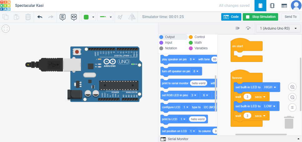
Tinkercad
Tikercad hosts visual drag and drop code blocks for programming arduino in a direct and simple way, so it requires no previous experience with syntax based programming. It also has online circuits simulator where it’s possible to directly test the created codes. The Code blocks are classified into the following categories:
Output — Blocks for controlling output devices Input — Blocks for reading input devices Notation — Blocks for adding comments Control — Control structures like adding delays, repeating, and if else statements Math — Blocks for logic and computation Variables — Custom variables that can be edited in your program
The bellow picture shows an example that programs the arduino uno built in led to blink on and off for three seconds.
A video for the circuit simulator for the blocks written code
Using Tinkercad was very easy and direct and I recommend it for beginners.
Arduino
Arduino is an open-source hardware and software company, project, and user community that designs and manufactures single-board microcontrollers and microcontroller kits for building digital devices. The language used to program the Arduino is C++. C++ is a superset of C, adding classes and changing the behavior of strcuts in subtle ways.
Arduino IDE
The Arduino Integrated Development Environment or Arduino Software (IDE) contains a text editor for writing code, a message area, a text console, a toolbar with buttons for common functions. It connects to the Arduino hardware to upload programs and communicate with them offline.
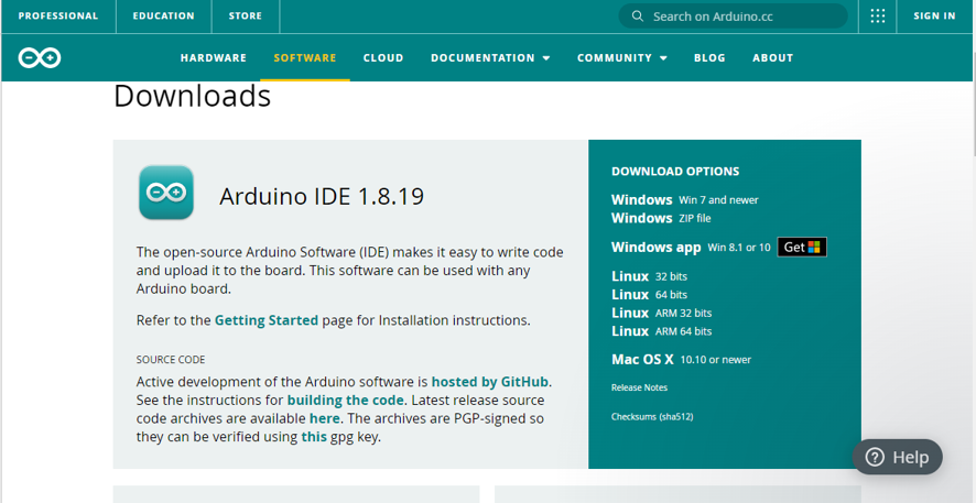
Click on this Link to download arduino IDE.
when you create new project this page apeears to you.
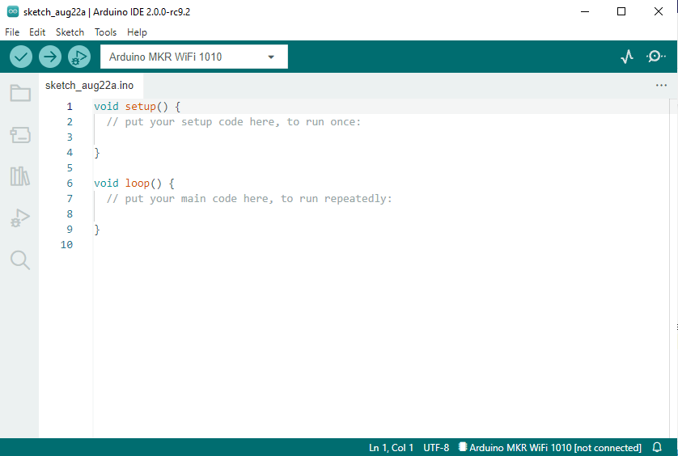
It has two void functions the setup() where the settins are made for the pin modes and the braud speed etc. this fuction only runs once when uploading the program and the loop() function where the actual program is written and it keeps repeating until the board is reset.
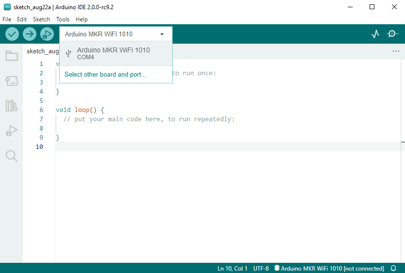
Before uploading any program to the microcontroller the IDE has to recognize the microcontroller type and the port number that it’s connected to.
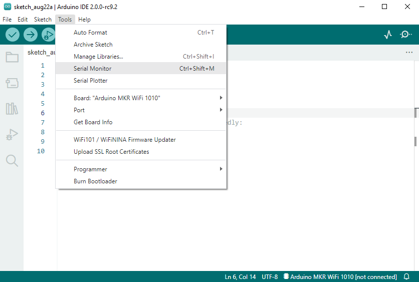
To open the serial monitor, you can find it in the tools bar.
I had better experience with coding with arduino IDE compared to with tinkercad as it gave me more advanced options.
Assignment 1
In the first assignment we were asked to test the MKR1010 microcontroller by uploading blink example to the board.
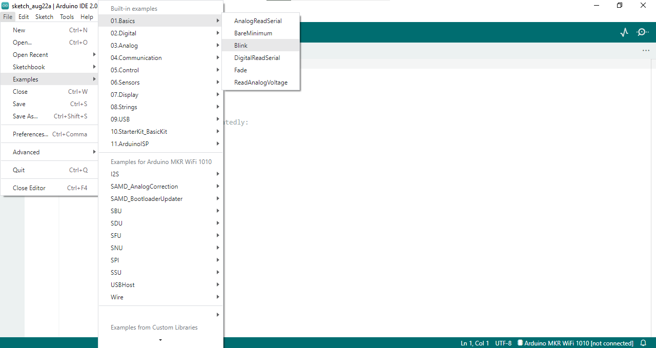
Click on File –> Examples –> 01.Basics –> Blink
The Blink code is as follows:
// the setup function runs once when you press reset or power the board
void setup() {
  // initialize digital pin LED_BUILTIN as an output.
  pinMode(LED_BUILTIN, OUTPUT);
}

// the loop function runs over and over again forever
void loop() {
  digitalWrite(LED_BUILTIN, HIGH);   // turn the LED on (HIGH is the voltage level)
  delay(1000);                       // wait for a second
  digitalWrite(LED_BUILTIN, LOW);    // turn the LED off by making the voltage LOW
  delay(1000);                       // wait for a second
}
What it does is that after configuring the mode for the built in led as an output pin in the setup() function. The led is programmed to turn on and off for a second by using the digitalWrite(Pin address, HIGH or LOW ).
Assignment 2
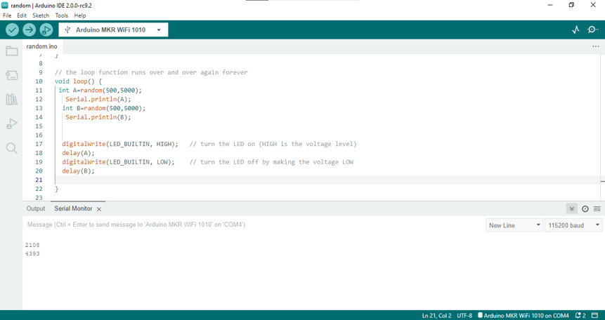
The second assignment was to make the led blink with a random delay. Using the same basic blink code in assignment 1, by adding random() function to generate a random number between 500 and 5000 and put it as an input in the delay() function.
// the setup function runs once when you press reset or power the board
void setup() {
  // initialize digital pin LED_BUILTIN as an output.
  pinMode(LED_BUILTIN, OUTPUT);
}

// the loop function runs over and over again forever
void loop() {
 int A=random(500,5000);
   Serial.println(A);
  int B=random(500,5000);
   Serial.println(B);


  digitalWrite(LED_BUILTIN, HIGH);   // turn the LED on (HIGH is the voltage level)
  delay(A);
  digitalWrite(LED_BUILTIN, LOW);    // turn the LED off by making the voltage LOW
  delay(B);

}
The below screenshot shows the generated delays in the serial monitor.
The video for the random blinking:
Assignment 3
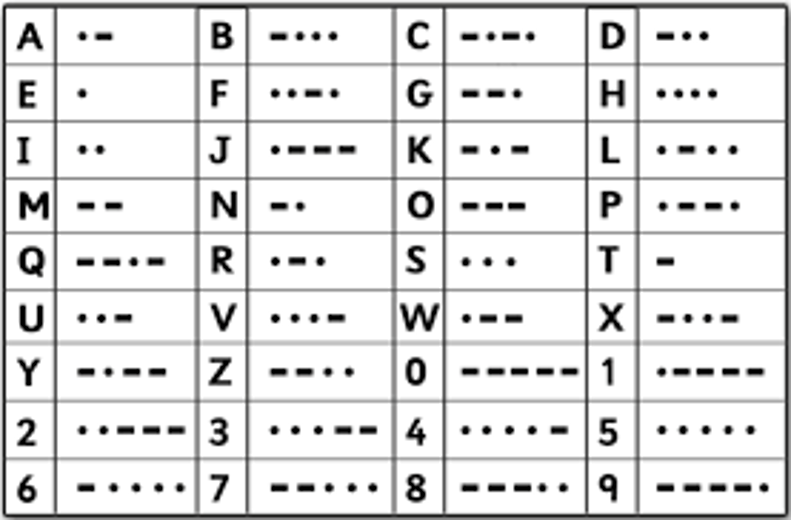
In assignment 3 we were asked to create morse code of a word from our choice by blinking the built in led following the next rules.
| dot . | 0.5 s ON |
|---|---|
| dash - | 1.5 s ON |
| between dot and dash | 0.5 s OFF |
| between letters | 2.5 s OFF |
The below table lists the morse code for every letter and number.
Later is the code for sending the word “shahroor” in morse code.
// the setup function runs once when you press reset or power the board
void setup() {
  // initialize digital pin LED_BUILTIN as an output.
  pinMode(LED_BUILTIN, OUTPUT);
}

// the loop function runs over and over again forever
void loop() {

  // S letter  ...
  digitalWrite(LED_BUILTIN, HIGH);   // turn the LED on (HIGH is the voltage level)
  delay(500);
  digitalWrite(LED_BUILTIN, LOW);    // turn the LED off by making the voltage LOW
  delay(500);
    digitalWrite(LED_BUILTIN, HIGH);   // turn the LED on (HIGH is the voltage level)
  delay(500);
  digitalWrite(LED_BUILTIN, LOW);    // turn the LED off by making the voltage LOW
  delay(500);
    digitalWrite(LED_BUILTIN, HIGH);   // turn the LED on (HIGH is the voltage level)
  delay(500);
  digitalWrite(LED_BUILTIN, LOW);    // turn the LED off by making the voltage LOW
  delay(2500);

    // H letter   ....
    digitalWrite(LED_BUILTIN, HIGH);   // turn the LED on (HIGH is the voltage level)
  delay(500);
  digitalWrite(LED_BUILTIN, LOW);    // turn the LED off by making the voltage LOW
  delay(500);
    digitalWrite(LED_BUILTIN, HIGH);   // turn the LED on (HIGH is the voltage level)
  delay(500);
  digitalWrite(LED_BUILTIN, LOW);    // turn the LED off by making the voltage LOW
  delay(500);
    digitalWrite(LED_BUILTIN, HIGH);   // turn the LED on (HIGH is the voltage level)
  delay(500);
  digitalWrite(LED_BUILTIN, LOW);    // turn the LED off by making the voltage LOW
  delay(500);
    digitalWrite(LED_BUILTIN, HIGH);   // turn the LED on (HIGH is the voltage level)
  delay(500);
  digitalWrite(LED_BUILTIN, LOW);    // turn the LED off by making the voltage LOW
  delay(2500);

    // A letter   .-
    digitalWrite(LED_BUILTIN, HIGH);   // turn the LED on (HIGH is the voltage level)
  delay(500);
  digitalWrite(LED_BUILTIN, LOW);    // turn the LED off by making the voltage LOW
  delay(500);
    digitalWrite(LED_BUILTIN, HIGH);   // turn the LED on (HIGH is the voltage level)
  delay(1500);                       /
  digitalWrite(LED_BUILTIN, LOW);    // turn the LED off by making the voltage LOW
  delay(2500);

    // H letter   ....
    digitalWrite(LED_BUILTIN, HIGH);   // turn the LED on (HIGH is the voltage level)
  delay(500);
  digitalWrite(LED_BUILTIN, LOW);    // turn the LED off by making the voltage LOW
  delay(500);
    digitalWrite(LED_BUILTIN, HIGH);   // turn the LED on (HIGH is the voltage level)
  delay(500);
  digitalWrite(LED_BUILTIN, LOW);    // turn the LED off by making the voltage LOW
  delay(500);
    digitalWrite(LED_BUILTIN, HIGH);   // turn the LED on (HIGH is the voltage level)
  delay(500);
  digitalWrite(LED_BUILTIN, LOW);    // turn the LED off by making the voltage LOW
  delay(500);
    digitalWrite(LED_BUILTIN, HIGH);   // turn the LED on (HIGH is the voltage level)
  delay(500);
  digitalWrite(LED_BUILTIN, LOW);    // turn the LED off by making the voltage LOW
  delay(2500);

     // R letter   .-.
    digitalWrite(LED_BUILTIN, HIGH);   // turn the LED on (HIGH is the voltage level)
  delay(500);
  digitalWrite(LED_BUILTIN, LOW);    // turn the LED off by making the voltage LOW
  delay(500);
    digitalWrite(LED_BUILTIN, HIGH);   // turn the LED on (HIGH is the voltage level)
  delay(1500);
  digitalWrite(LED_BUILTIN, LOW);    // turn the LED off by making the voltage LOW
  delay(500);
    digitalWrite(LED_BUILTIN, HIGH);   // turn the LED on (HIGH is the voltage level)
  delay(500);
  digitalWrite(LED_BUILTIN, LOW);    // turn the LED off by making the voltage LOW
  delay(2500);

     // O letter    ---
    digitalWrite(LED_BUILTIN, HIGH);   // turn the LED on (HIGH is the voltage level)
  delay(1500);
  digitalWrite(LED_BUILTIN, LOW);    // turn the LED off by making the voltage LOW
  delay(500);
    digitalWrite(LED_BUILTIN, HIGH);   // turn the LED on (HIGH is the voltage level)
  delay(1500);
  digitalWrite(LED_BUILTIN, LOW);    // turn the LED off by making the voltage LOW
  delay(500);
    digitalWrite(LED_BUILTIN, HIGH);   // turn the LED on (HIGH is the voltage level)
  delay(1500);
  digitalWrite(LED_BUILTIN, LOW);    // turn the LED off by making the voltage LOW
  delay(2500);

     // O letter   ---
    digitalWrite(LED_BUILTIN, HIGH);   // turn the LED on (HIGH is the voltage level)
  delay(1500);
  digitalWrite(LED_BUILTIN, LOW);    // turn the LED off by making the voltage LOW
  delay(500);
    digitalWrite(LED_BUILTIN, HIGH);   // turn the LED on (HIGH is the voltage level)
  delay(1500);
  digitalWrite(LED_BUILTIN, LOW);    // turn the LED off by making the voltage LOW
  delay(500);
    digitalWrite(LED_BUILTIN, HIGH);   // turn the LED on (HIGH is the voltage level)
  delay(1500);
  digitalWrite(LED_BUILTIN, LOW);    // turn the LED off by making the voltage LOW
  delay(2500);

    // R letter    .-.
    digitalWrite(LED_BUILTIN, HIGH);   // turn the LED on (HIGH is the voltage level)
  delay(500);
  digitalWrite(LED_BUILTIN, LOW);    // turn the LED off by making the voltage LOW
  delay(500);
    digitalWrite(LED_BUILTIN, HIGH);   // turn the LED on (HIGH is the voltage level)
  delay(1500);
  digitalWrite(LED_BUILTIN, LOW);    // turn the LED off by making the voltage LOW
  delay(500);
    digitalWrite(LED_BUILTIN, HIGH);   // turn the LED on (HIGH is the voltage level)
  delay(500);
  digitalWrite(LED_BUILTIN, LOW);    // turn the LED off by making the voltage LOW
  delay(5000);

}
The video for the morse code:
Assignment 4
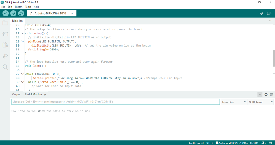
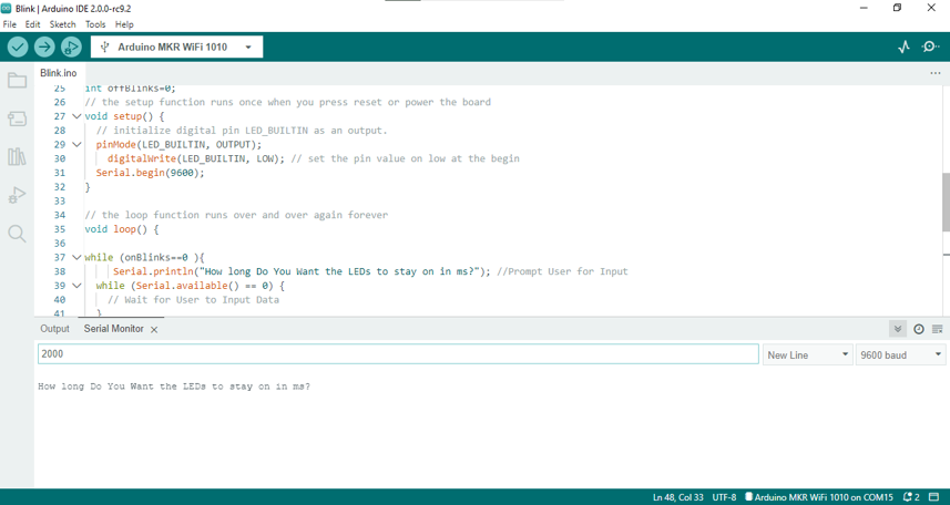
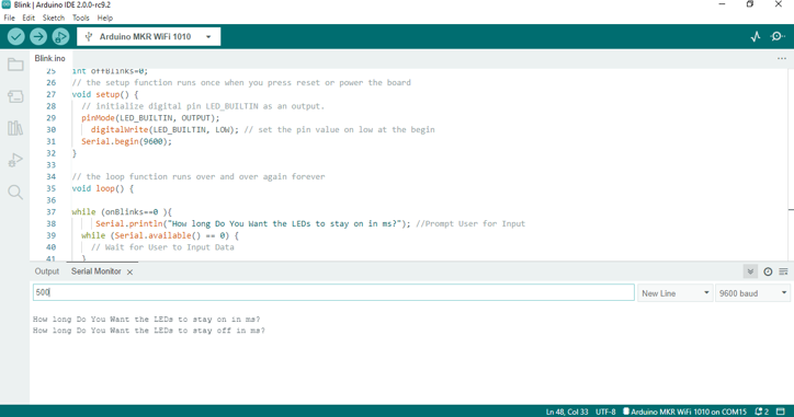
In the last assignment the task was to write a code that prompts the user to input the desired delay for the blinking time.
int on=0;
int off=0;

// the setup function runs once when you press reset or power the board
void setup() {
  // initialize digital pin LED_BUILTIN as an output.
  pinMode(LED_BUILTIN, OUTPUT);
  digitalWrite(LED_BUILTIN,LOW);  // set the pin value on low at the begin
  Serial.begin(9600);
}

// the loop function runs over and over again forever
void loop() {
  while (on==0){
    Serial.println("How long do you want the LEDs to stay on in ms?");  // prompt user for input
    while (Serial.available() ==0){
      // wait for user to input data
    }
    on = Serial.parseInt();  // read the data the user has input
  }

  while (off==0){
    Serial.println("How long do you want the LEDs to stay off in ms?");  // prompt user for input
    while (Serial.available() ==1){
      // wait foe user to input data
    }
    off = Serial.parseInt();  // read the data the user has input
  }

  for(int i=0; i<5; i++){
    digitalWrite(LED_BUILTIN,HIGH);  // turn the LED on
    delay(on);  // wait for a second
    digitalWrite(LED_BUILTIN,LOW);   // turn the LED off
    delay(off);
    }
  }
The onBlinks and offBlinks variables are defined first and given the value of zero. The program will wait for the onBlink variable to get updated first and will check Serial.available() status and will only pass on the code when changed and move to the offBlinks variable. Serial.parseInt() function is used to get the data sent by the user and save it in the defined variables. The blinking part of the code is made to repeat for five times until going on the top of the loop function again.
The steps for user sending the data are shown below:

The video for the prompted delay for the blinking: