7. Input & Output device
This week I used input and output devices to send and accept data from and to the surrounding environment.
Introduction
An input device sends information to the microcontroller for processing,and it only allow for input of data to a microcontroller. While an output device reproduces or displays the results of that processing and they only receive the output of data from another device.
Microcontrollers accept and send signals in digital or analogue forms. While digital has two values: on and off, analog has many (infinite) values. The microcontroller don’t really do analog, they quantize.
The microcontroller needs Input and output devices to get information from the enviroment and make changes to the enviroment. This is done by the aid of a code that instruct the working of the microcontroller and sets the relationship between it and those devices.
Task 1
The first task was to take readings from a sensor. In my case I chose DHT11 temperature and humidity sensor.
The DHT11 is a commonly used Temperature and humidity sensor that comes with a dedicated NTC to measure temperature and an 8-bit microcontroller to output the values of temperature and humidity as serial data.
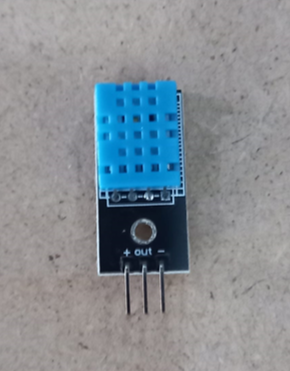
The above picture shows the DHT11 sensor.
The sensor measures the change in humidity from the capacitance change in the capacitor constituting of two electrodes with a moisture holding substrate as a dielectric material inside the sensor. The IC measures the change in capacitance value and convert them to digital signals.
For measuring temperature DHT11 has a Negative Temperature coefficient thermistor, which causes a decrease in its resistance value with increase in temperature. Thermistors are made of semiconductors that are known for high sensitivity.
The electrical signals can easily be converted to the physical signals by knowing the relationship between them. This conversion is done inside the sensor, using libraries or from using a pretested equation to get meaningful results.
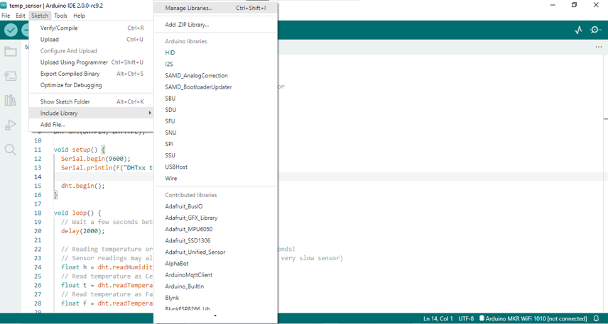
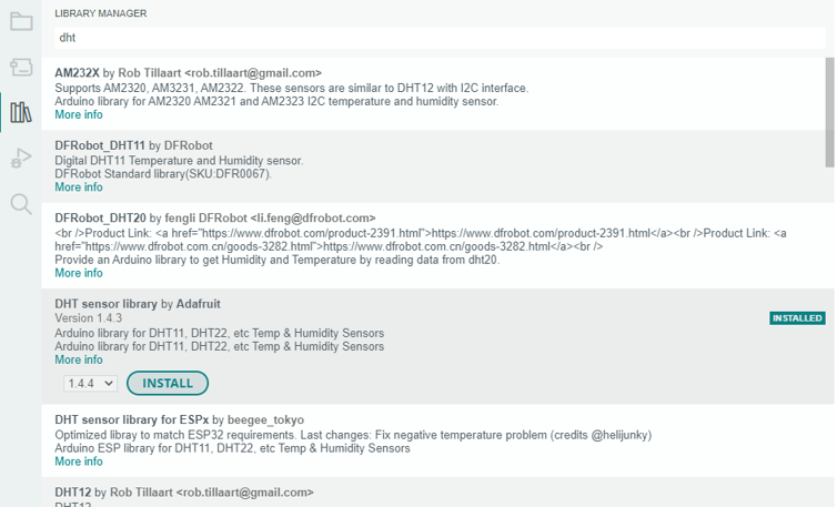
The DHT library is installed by Sketch –> Include library –> Manage libraries and searching for DHT sensor library by adafruit.
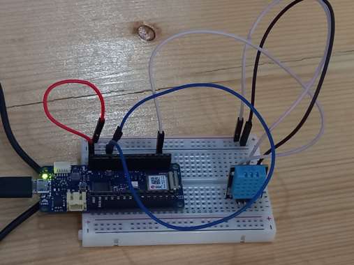
The data pin was connected to port 7 in the microcontroller.
Following is the uploaded code for taking data from the DHT11 sensor:
#include "DHT.h"

#define DHTPIN 7

#define DHTTYPE DHT11

DHT dht(DHTPIN, DHTTYPE);

void setup() {
  Serial.begin(9600);
  Serial.println(F("test"));

  dht.begin();
}

void loop() {

  delay(3000);

  float h = dht.readHumidity();

  float t = dht.readTemperature();

  float f = dht.readTemperature(true);

  float hif = dht.computeHeatIndex(f, h);

  float hic = dht.computeHeatIndex(t, h, false);

  Serial.print(F(" Humidity: "));
  Serial.print(h);
  Serial.print(F("%  Temperature: "));
  Serial.print(t);
  Serial.print(F("C "));
  Serial.print(f);
  Serial.print(F("F  Heat index: "));
  Serial.print(hic);
  Serial.print(F("C "));
  Serial.print(hif);
  Serial.println(F("F"));
}
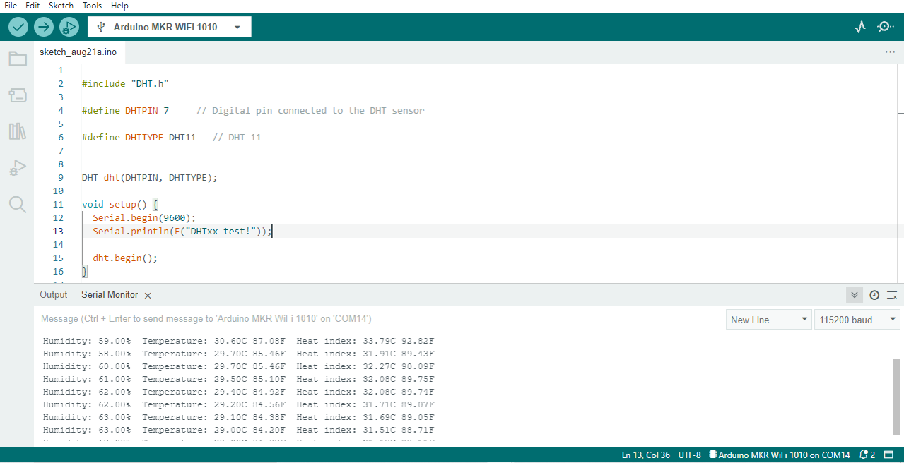
The picture below shows the temperature and humidity readings in the serial monitor:
Information on How to Use Temperature and Humidity (DHT) Sensors were taken from thislink
Task 2
The second task was to test an output device. In my case I used servo motor SG90.
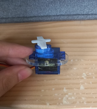
Servo Motor SG90 is a tiny and lightweight server motor with high output power. Servo can rotate approximately 360 degrees (180 in each direction). They have a geared output shaft which can be electrically controlled to turn one (1) degree at a time. A servo motor is a closed-loop system that uses position feedback to control its motion and final position.
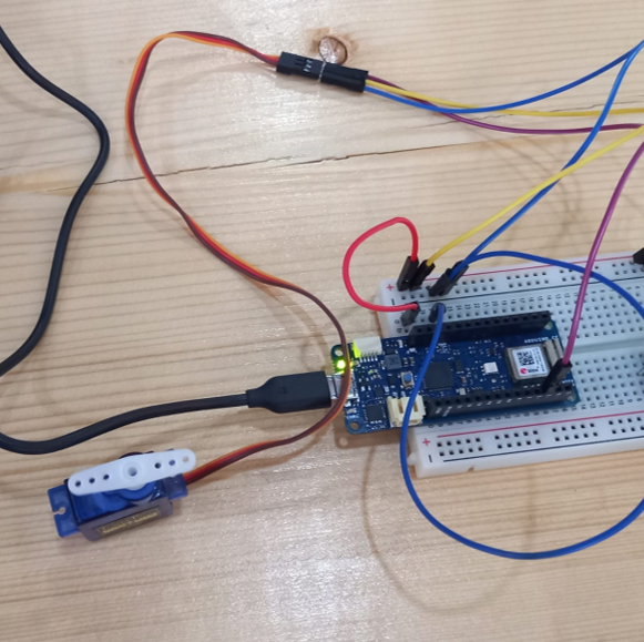
The servo motor connection with MKR1010 is shown below:
The code written below was used to rotate the servo motor 180 dgrees in each direction.
#include<Servo.h>
Servo Myservo;
int i;
void setup()
{
Myservo.attach(3);
}

void loop()
{


for(i=0;i<=180;i++){
Myservo.write(i);
delay(10);
}
  delay(1500);

  for(i=180;i>=0;i--){
Myservo.write(i);
delay(10);
}
  delay(1500);

}
The below video shows the servo motor rotating:
Task 3
The third task was to combine input and output elements and let them interact with each other, so that the output device do specific logical actions based on preassigned rules and conditions depending on the state of the input device.
In my case, I programmed the servo motor to rotate when the temperature exceeds 20 degrees. The uploaded code is written below:
#include<Servo.h>
Servo Myservo;
int i;

#include "DHT.h"

#define DHTPIN 7

#define DHTTYPE DHT11

DHT dht(DHTPIN, DHTTYPE);

void setup() {
  Serial.begin(9600);
  Serial.println(F("test"));
  Myservo.attach(3);

  dht.begin();
}

void loop() {

  delay(3000);

  float h = dht.readHumidity();

  float t = dht.readTemperature();

  float f = dht.readTemperature(true);

  float hif = dht.computeHeatIndex(f, h);

  float hic = dht.computeHeatIndex(t, h, false);

  Serial.print(F(" Humidity: "));
  Serial.print(h);
  Serial.print(F("%  Temperature: "));
  Serial.print(t);
  Serial.print(F("C "));
  Serial.print(f);
  Serial.print(F("F  Heat index: "));
  Serial.print(hic);
  Serial.print(F("C "));
  Serial.print(hif);
  Serial.println(F("F"));

if(t>20){
  for(i=0;i<=180;i++){
Myservo.write(i);
delay(20);
}
  delay(1500);

  for(i=180;i>=0;i--){
Myservo.write(i);
delay(20);
}
  delay(1500);
}

}
The next video shows the servo motor rotating for tempertaures exceeding 20.
The next video shows the servo motor settled for tempertaures less than 20.
Task 4
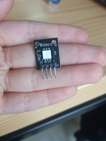
In the final task we programmed KY-009 RGB FULL COLOR LED SMD MODULE to light with red, green and blue colors in addition to a color by our choice made by mixing the preceding colors with known degrees.
changing the PWM value on each of the three primary colors
Pulse Width Modulation or PWM is a method to get analog signals from digital signals. Digital control is used to create a square wave, a signal switched between on and off. This on-off pattern can simulate voltages in between the full Vcc of the board and off (0 Volts) by changing the portion of the time the signal spends on versus the time that the signal spends off.
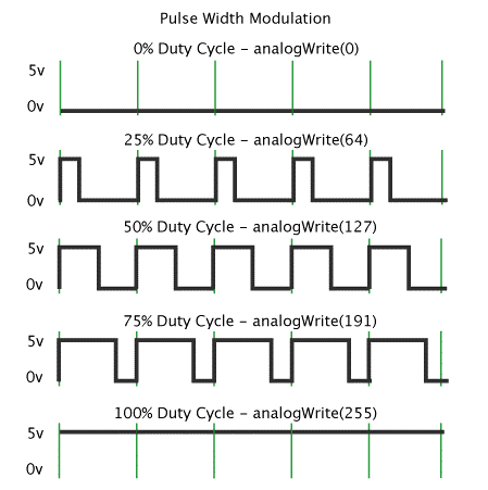
image source
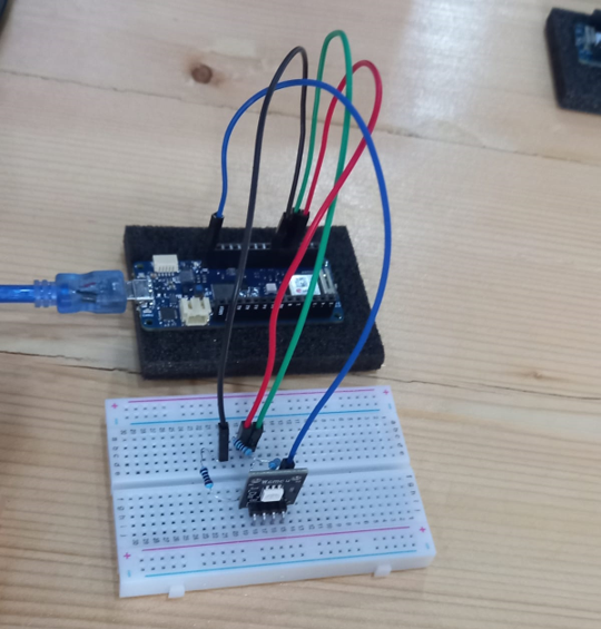
The next table shows the connection for the KY-009 pins and the microcontroller. Resistors are used to limit the current flowing through the leds.
The forward voltage for the red, blue and green leds are 1.8V, 2.8V and 2.8V respectively while the forward current is limited to 20 mA. To calculate the resistors values in series with the leds while keeping in mind that the MKR1010 Vcc is 3.3V:
| KY-009 | Breadboard | arduino |
|---|---|---|
| R | (3.3-1.8/20m)=75 ohm | Pin 9 |
| G | (3.3-2.8/20m)=25 ohm | Pin 10 |
| B | (3.3-2.8/20m)=25 ohm | Pin 11 |
| - | Vcc |
I used 100 ohms, 47 ohms and 47 ohms as they were the available. I chose resistors with values higher than the calculated ones to prevent the leds from damage due to excess of current.
#define Rpin 9
#define Gpin 10
#define Bpin 11
int r = 0, g =0 , b = 0;
void RGB(int r, int g, int b)
{ r = 255 - r;
 g = 255 - g;
 b = 255 - b;
 analogWrite(Rpin, r);
 analogWrite(Gpin, g);
 analogWrite(Bpin, b); }
 void setup(){
   pinMode(Rpin,OUTPUT);
   pinMode(Gpin,OUTPUT);
   pinMode(Bpin,OUTPUT);


 }
   void loop(){

    RGB(255,0,0);//RED
   delay(1000);
   RGB(0,255,0);//Green
   delay(1000);
   RGB(0,0,255);//Blue
   delay(1000);
    RGB(54,188,186);// the chosen color
   delay(1000); }
Problems faced
We had a problem first in getting the KY-009 RGB to work. As the RGB module we were using was a common anode RGB module while we were following the connections for the common cathode RGB module as it was labeled. We fixed this problem by putting the ground pin in the Vcc pin instead.
Useful links
-Basics of PWM (Pulse Width Modulation) -DHT11 Sensor and Its Working -KY-009 RGB SMD-LED -How to Control Servo Motors with Arduino