3. Computer controlled cutting
 Credits to MegaCrit for the second picture.
Laser cutting is simple in theory, a high energy light beam is focused on a sheet of material to vaporize it, which can cut it, or it can be used for engraving. Laser cutting works by directing the output of a high-power laser most commonly through optics. The laser optic and CNC (computer numerical control) are used to control the material or the cutting tool generating the beam. There are three types of laser cutting machines. CO2 laser cutting machine, Fiber lasers and Vandate crystal lasers. Each uses different base materials to generate the laser beam used in the cutting process.
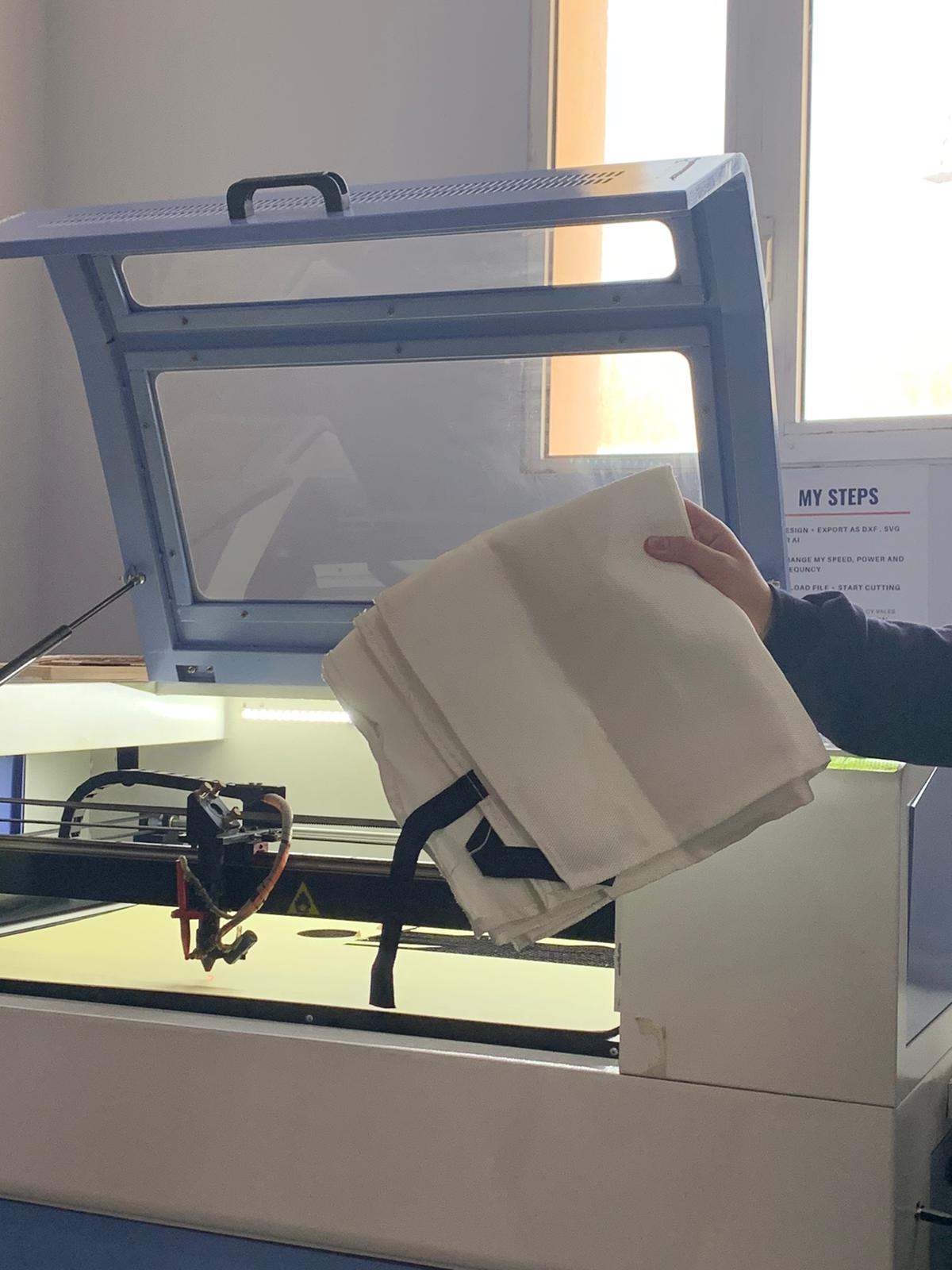
CO2 laser cutting machine at Fab Lab Bahrain
For our cuts, we used a CO2 laser cutting machine to create a press fit construction kit. The machine has a moving cutting tool that moves in a similar manner to the CNC machine. For my design, I chose to make two spheres connected to each other. Before cutting, we had to create a cut to test the joints. The cut had a similar shape to a comb, with the joint size decreasing in increments of 0.05 after each tooth. The purpose of this shape is to find out the best possible joint size for our material, which was 1.15 height. Setting the joints to be the same size as the height caused the joints to be loose. After trying different sizes, we found out that 1mm was the best suitable size in which joints would fit without being difficult to attach.
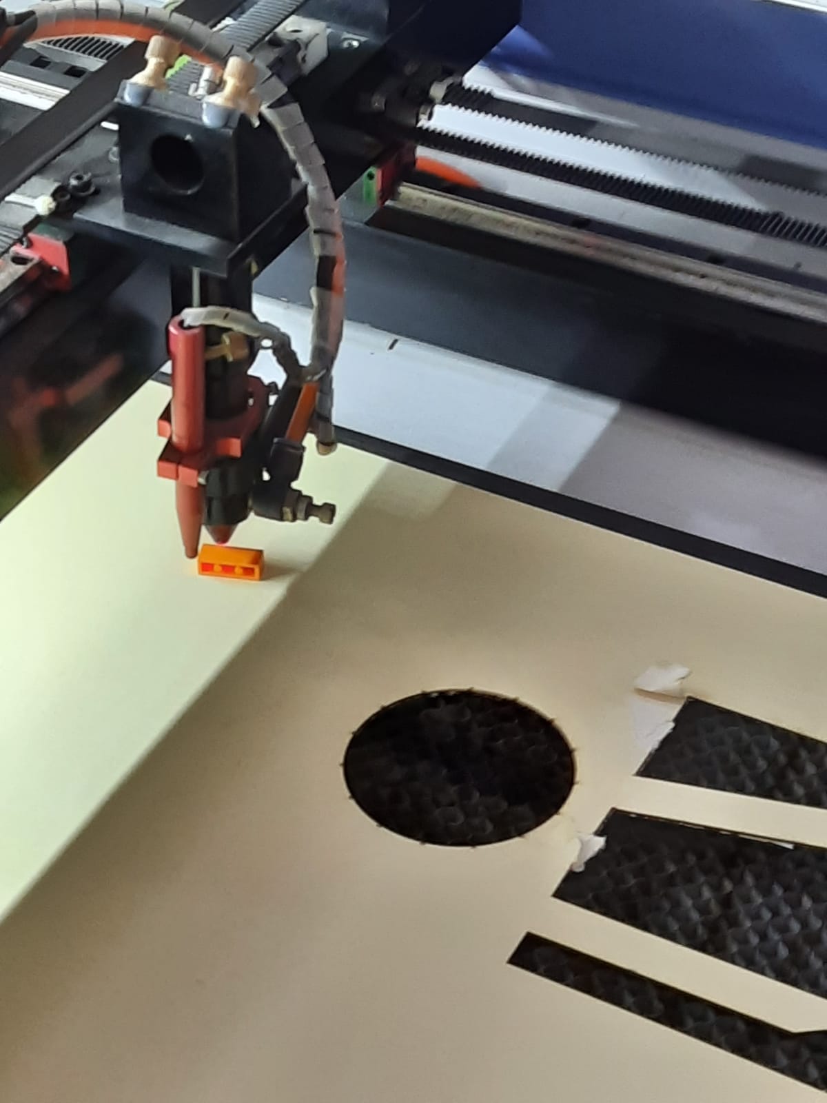
The cutting bit used by the CO2 machine
After completing our designs, we started cutting. First step was to export our sketches into the machine’s software. In my case I had multiple objects I wanted to cut so I made several copies of them to be cut. My design was that of two spheres connected to each other, and it was done through two different parts.
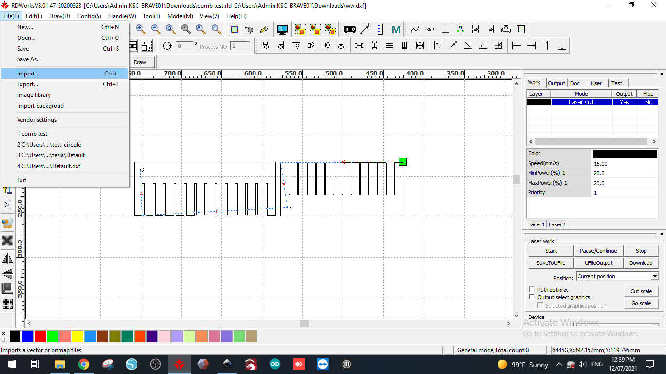
The interface of the software used to export sketches to the CO2 machine. Here we made a shape with multiple slots, each decreasing in size to test tolerance.
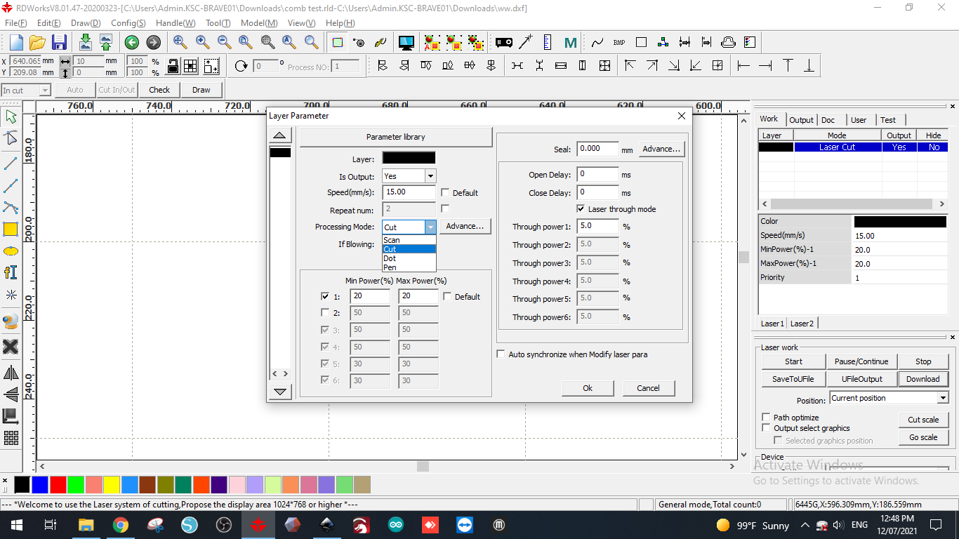
Setting the cutting parameters for the CO2 machine
Next step is setting up the machine. We turned it on, and used the interface to calibrate it. We needed to find an origin spot so we moved the cutting part around the material to find the most suitable area to start cutting while minimizing material loss. For Z axis, the material interface had buttons to move the material up and down, so we used an 8mm lego piece to create a distance of nearly 8mm between the cutting tool and the material. We also used the frame option provided in the material interface to get an idea of the general area to be cut by the machine to minimize error. After all of this is done, we started cutting by choosing that option in the software.

Interface of the CO2 machine
Safety precautions when cutting using the CO2 machine is to close the machine and keep a blanket nearby in case of fire.
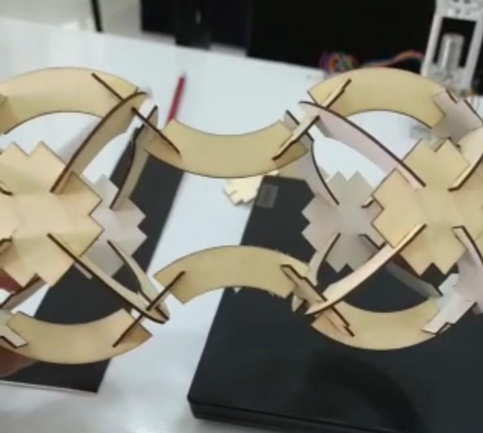
Making the Press-fit construction kit
The image of the two connecting spheres are made from what is called a Press-fit construction kit. Basically smaller pieces that are assembled together, to create the desired shape.
The design is based on an image I saw online, where a sphere was made from two different pieces only. Basically each sphere would contain six rectangular pieces connected to each other by pieces that are the shape of a quarter circle arch.
with the design specification that we were given, I made both pieces using Fusion 360. All that was necessary after is to ensure that I can cut enough pieces. As a measure of precaution, we were also instructed to print more than what is needed just in case of failure to save time.
After designing the pieces using Fusion 360, the designs were transferred to the CO2 laser cutting machine software, to be ready for cutting. This is a similar process to the one above, where we tested the tolerance for the material used.
VINYL CUTTER
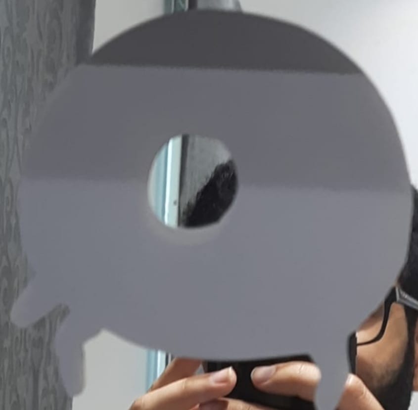
Vinyl cutter is a machine that operates quite similarly to the CO2 cutter in the sense that material is inserted in the machine and it cuts it precisely. The vinyl cutter usage includes cutting stickers, which is what I did. I found an image of something online that I wanted to make a sticker out of, and exported it to the vinyl machine cutting software Cricut. The software did the necessary steps such as forming lines around areas of cuts. The final step was to place the sticker material on a mat provided by the machine’s manufacturer, and insert the mat into the machine and operate it.
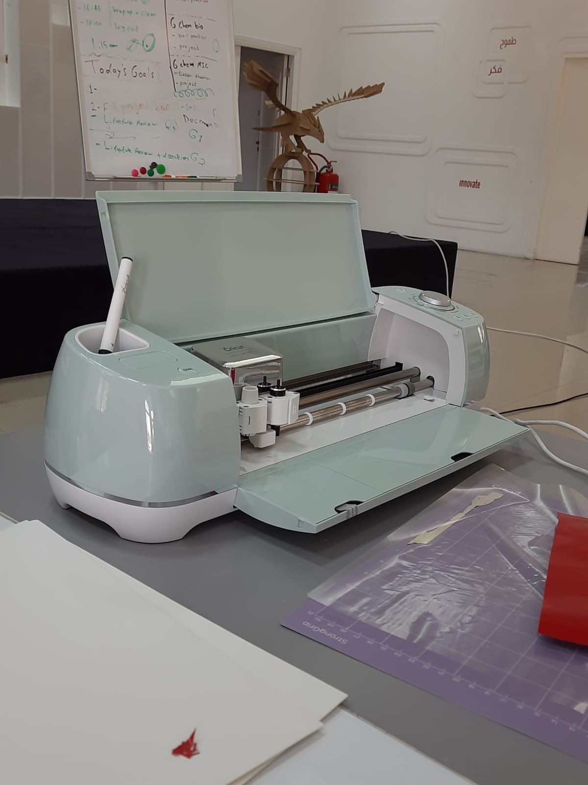
The Vinyl Machine.

 Finalizing the cutting process
The machine then goes to cut the desired shape. Do keep in mind that different colors are difficult, although attainable by cutting different parts and sticking them together, which can be a rather tedious process. Moreover, certain details on the image cannot be conveyed by the software, as it will only cut the basic shape of the image.
The sticker is inserted in the machine on a slightly sticky mat to ensure the stability of the cut. This mat is re-useable, though it needs to be changed every once in a while.
The vinyl machine will cut the sticker into a similar shape to that of the one displayed on the final picture. It will also cut around the area specified on the software, which is useful for saving material.
All that is left after is to remove the sticker material from the cutting mat, and then remove the desired shape produced by the vinyl cutting machine.