8. Input/Output devices
Brief intro of input and output devices, also known as I/O devices.
Input/Output devices are communication devices, usually between a system and a human. Input devices are used to send information to the system. An example of an input device are keyboards. Buttons you press on a keyboard are transformed as symbols to the computer. Output devices are the opposite, they’re used to transform information from the system into something understandable by humans such as light and sound. Speakers are an example of such devices. Data is output as sounds which can be interpreted by humans, this can range from music to recorded voice notes.
Input devices
For input devices, I tested two devices. First one is called mercury tilt switch, also known as KY-017 MERCURY TILT SWITCH MODULE. It’s a sensor with a mercury sphere that is used to close or open the circuit in the sensor, basically creating an off and on switch depending on the position of the sphere. Since the mechanism is simple the code as well is simple, I coded it to turn on the Arduino Nano device led light on or off depending on the position. Sample codes can be found online, particularly on Arduino’s website. Although the device is simple, it can be used for many things, including an anti-box theft device that triggers an alarm if the box is moved. The circuit can also be simply connected. The device has 3 symbols to help with connecting the circuit. The plus symbol is connected to the power supply, which is the 5 volt pin on the Arduino Nano microcontroller. The negative symbol is connected to the ground pin. Finally, the s symbol is connected to one of the digital pins. Online documentation of the device which can be available on Arduino’s website states that it must be connected to the D3 pin on the Nano device.
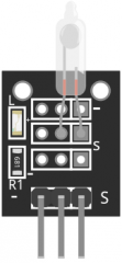
Here is a picture of how the mercury device tilt switch looks like.
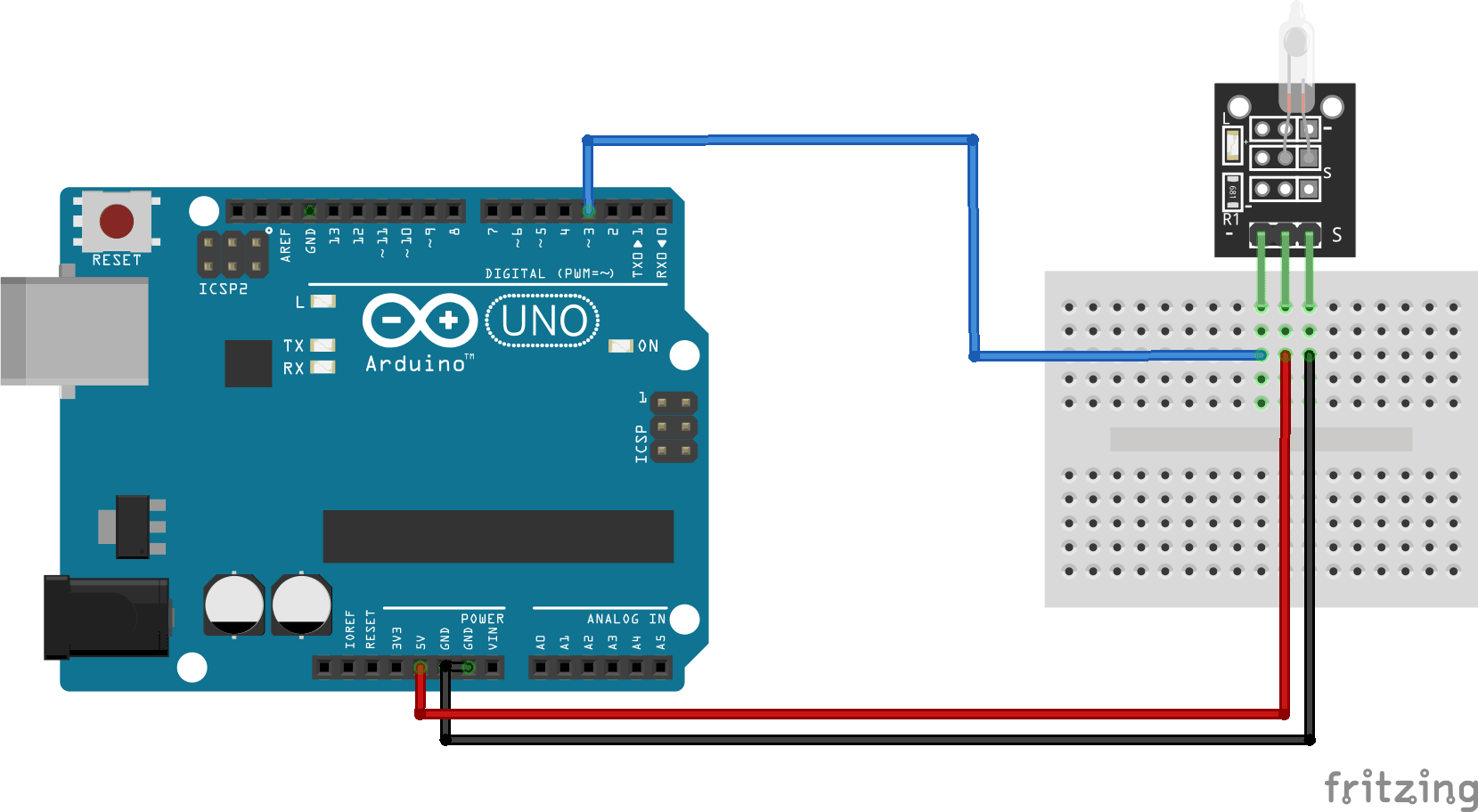
This diagram, which can be found online, was of great help while I was figuring out the circuit connection.
Moving on to the code, here is a sample of the code I have used.
int led_pin = 13; // Define the LED interface
int switch_pin = 3; // Definition of mercury tilt switch sensor interface
int val; // Defines a numeric variable
void setup()
{
pinMode(led_pin, OUTPUT);
pinMode(switch_pin, INPUT);
}
void loop()
{
val = digitalRead(switch_pin); // check mercury switch state
if(val == HIGH)
{
digitalWrite(led_pin, HIGH); }
else {
digitalWrite(led_pin, LOW); }
}
This all can be found in arduinomodules.info.
To explain the code briefly, we first start by defining the variables. In the setup portion, we write the code we want to occur once only, in this case we simply chose the input and the output portions of both the microcontroller and the switch. Loop is the continuous process which occurs while the device is powered. In this instance, the process powers up the microcontroller led light if the mercury tilt switch is powered up, and powers it down if the mercury tilt switch is powered down. This process can be reversed as with a simple change to the code. One thing to note is that despite the fact that we don’t have a dedicated output device connected, the led on the microcontroller functions as a form of output as light is one of the many forms of output.
The next input device I used is a temperature sensor. I was able to code it to inform me of whether the temperature exceeded a certain threshold or not. This device was far more complicated to use than the simple mercury tilt switch. As with the former, sample codes are available online. More information can be found here..
Output devices.
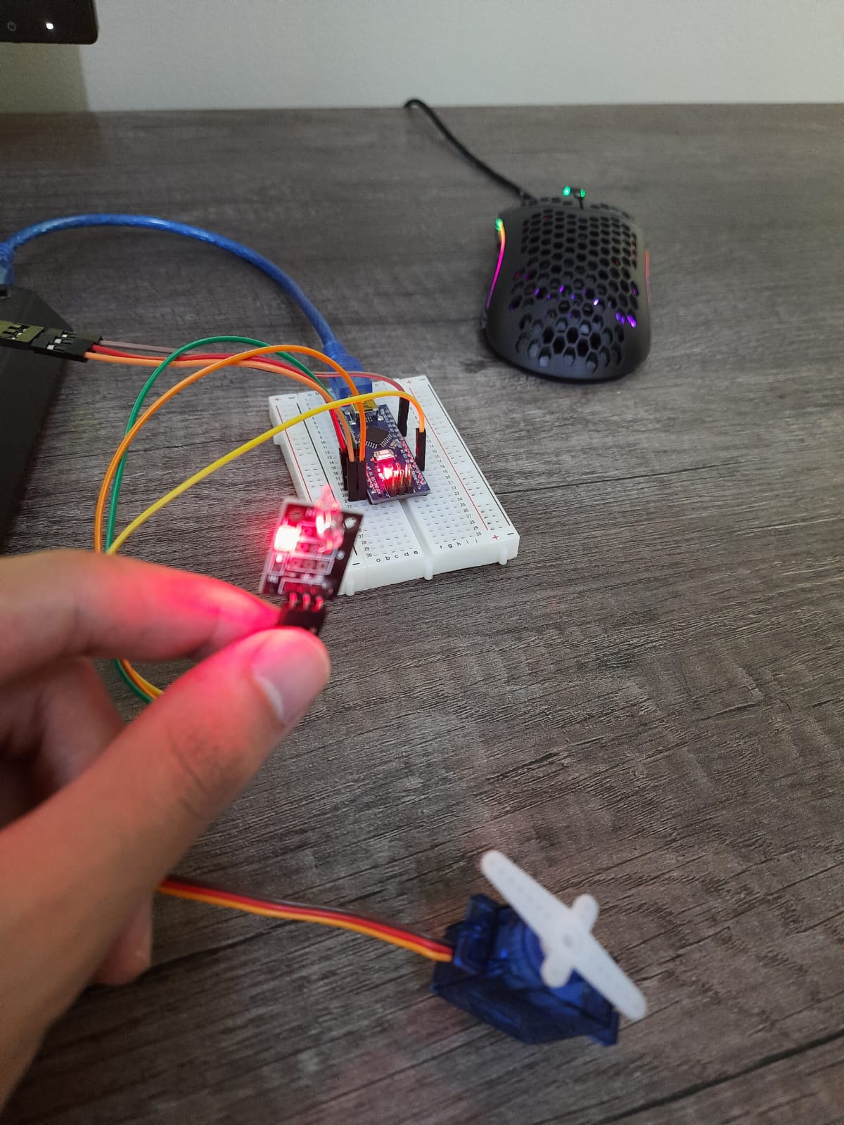
Moving to output devices, I was given a servo motor to experiment with. I was able to find sample codes online alongside the sample codes provided by Arduino after installing the servo library. The device can be coded to do multiple things from sweeping to simply vibrating to moving slowly. This device can be used for multiple small projects such as simple automatic door lockers or a simple walker.
As with the previous devices, information is accessible and available online.
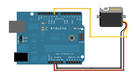 This image illustrates the circuit’s connections.
Moving on to the code, a necessary step must be taken before being able to configure the servo motor.
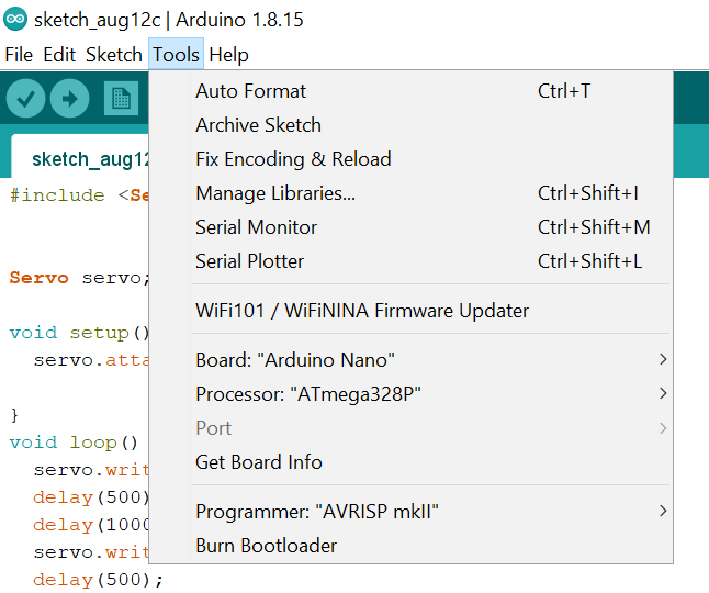 In the Arduino software interface, click on tools, then move on to manage libraries. Then search for Servo, and make sure it is installed. Otherwise, you wouldn’t be able to code the servo motor. Basically what’s happening is that the Arduino software lacks the necessary information to recognize and be able to configure the servo motor, but thankfully this information can easily be downloaded from the software.
Now to the code, I will be using the sample sweep code that comes with the servo motor library.
/* Sweep by BARRAGAN http://barraganstudio.com This example code is in the public domain.
modified 8 Nov 2013 by Scott Fitzgerald http://www.arduino.cc/en/Tutorial/Sweep */
/#include
Servo myservo; // create servo object to control a servo // twelve servo objects can be created on most boards
int pos = 0; // variable to store the servo position
void setup() {
myservo.attach(9); // attaches the servo on pin 9 to the servo object
}
void loop() {
for (pos = 0; pos <= 180; pos += 1) { // goes from 0 degrees to 180 degrees
// in steps of 1 degree
myservo.write(pos); // tell servo to go to position in variable ‘pos’
delay(15); // waits 15ms for the servo to reach the position
}
for (pos = 180; pos >= 0; pos -= 1) { // goes from 180 degrees to 0 degrees
myservo.write(pos); // tell servo to go to position in variable ‘pos’
delay(15); // waits 15ms for the servo to reach the position
}
}
As with the previous code, we perform the first necessary two steps which are defining and setup. However this time we include #include
As for the loop, the servo motor is coded to 180 degree positive and negative in a loop. Basically the microcontroller tracks the position of the motor in a value called pos, and depending on the value of pos the motor moves. This creates a sweeping movement in which the motor rotates a certain degree on one side, and after a delay rotates back to the same position.
Utilizing both Input and Output devices in one device.
One of our tasks for this week was also to make something incorporating both input and output devices. This was simply done by merging the codes for the sensor and the code for the output device, and usage of if statement. In my case I coded the servo motor to sweep if the tilt switch is in a particular position, or simply stop if the switch is in the other position. The motor can also be coded to move in different directions based on the state of the mercury tilt switch.
/#include
Servo myservo; // create servo object to control a servo // twelve servo objects can be created on most boards
int led_pin = 13; // Define the LED interface
int switch_pin = 3; // Definition of mercury tilt switch sensor interface
int val; // Defines a numeric variable
int pos = 0; // variable to store the servo position
void setup()
{
pinMode(led_pin, OUTPUT);
pinMode(switch_pin, INPUT);
myservo.attach(9); // attaches the servo on pin 9 to the servo object
}
void loop()
{
val = digitalRead(switch_pin); // check mercury switch state
if(val == HIGH)
{
digitalWrite(led_pin, LOW);
}
else
{
digitalWrite(led_pin, HIGH);
for (pos = 0; pos <= 90; pos += 1) {
myservo.write(pos); // tell servo to go to position in variable ‘pos’
delay(15); // waits 15 ms for the servo to reach the position
}
for (pos = 90; pos >= 0; pos -= 1) { // goes from 180 degrees to 0 degrees
myservo.write(pos); // tell servo to go to position in variable ‘pos’
delay(15); // waits 15 ms for the servo to reach the position
}
}
}
As previously mentioned, we begin by defining values and setting up the necessary information for the device to utilize and function. But what I did here was basically take the code of the sweeping movement and create a conditional statement in the loop to power up the motor and the microcontroller led depending on the position of the mercury tilt switch.