5. Large format CNC
The focus of this week’s work was using the CNC machine to produce what we’ve learned to design in 3D designing softwares such as Fusion 360 which was mainly used.
A CNC machine is a motorized maneuverable tool and often a motorized maneuverable platform, which are both controlled by a computer, according to specific input instructions. Instructions are delivered to a CNC machine in the form of a sequential program of machine control instructions such as G-code and M-code, then executed. The program can be written by a person or, far more often, generated by graphical computer-aided design (CAD) software and/or computer aided manufacturing (CAM) software.
Front look of Fab Lab Bahrain’s CNC machine
Sketches were exported from our designs in Fusion 360 to be used as the basis for cutting through the CNC machine. One particular challenge I have encountered during this process is needing to remodel my sketches based on the upper surface of the part as opposed to the bottom surface of the part. When it comes to designing in 3D softwares, what I have learned to do is sketch a basic shape of the body I am aiming to create and extrude it upwards. Fortunately, Fusion 360 has a tool that can ease this process, which can be found when creating a sketch by click create under the sketchable shapes, going into project/include then into include 3D geometry. All you need to do is click on the surface and the software itself would generate a sketch based on the surface.
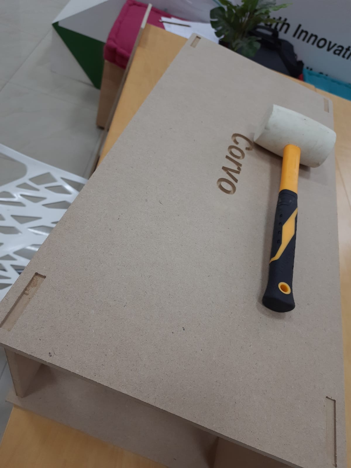
My design featured two sheets of wood being held on top of each other using 4 pillars on each corner, but creating the pillars would’ve proven to be time consuming owing to the fact that the wooden sheet we used is incapable of being formed into pillars easily using a CNC machine. It’s possible to cut several circles and attach them to each other throughout joints, but such a process would be time consuming. Moving on, I changed the design from using pillars to using rectangular pieces that would fit into both the lower and upper wooden sheet. I extended these rectangular pieces into both upper and lower wooden sheets, and the purpose of this extension was to use the joints tool in Fusion 360, as it would automatically create joints where materials intersect. Lastly, I did some fillet work on the corners of my design, and since the design was supposed to be a box to be used by the parrot I am raising, I decided to engrave his name on it at the top.
Upon completion, we’re now one step away from fully creating our designs using the CNC machine. In this step the limitations of the CNC machine become apparent as well. Our sketches were transported into a different software named VCarve to become readable by the CNC. Throughout this step I have learned that certain things need to be adjusted for the machine, such as certain designs being very difficult to create by a beginner. The wooden sheet as well had a limit of 11 mm height, which was also something to factor in when it comes to designs. Another example of limitations is when I had to change my design to remove a frame that I have designed simply because creating the parts and making them attach to the main body of the design using the CNC machine proved to be challenging, especially considering the time frame I had to create my design. One other limitation I have noticed when it comes to designing is that the machine cuts one side only, therefore, attention must be paid to the design as to not require the machine to be used for cutting from both sides. This is known as undercut. In this instance, I had a part that had writing on the top and needed to be cut in the bottom to fit the joints. Because of the limitation of the machine, the joint cuts needed to be thorough or otherwise the text on the top needed to be removed. Because of this, I have also added a small section to the rectangular pieces separating the bottom area and the top area, as a method to ensure that the top part of the design would be able to fit in the necessary joints only, and no more. Finally, tolerance was something important to include in the design. I chose a tolerance of 0.35mm for my joints, but I made a mistake initially with the tolerance and reduced the size of the joints by 0.35mm on both sides as opposed to one side. The purpose of this change was to ensure that the joints would not be loose, although increasing the tolerance by too much has caused my parts to not fit in at all, which meant I needed to recut my parts again as the previous ones would need a lot of work to be functional. The joint tolerance can easily be accomplished by using surface offset features in fusion 360, or simply just modifying the sketches to account for the tolerance.
After importing our sketches into the VCarve software, we have several steps to perform to ensure smooth cutting. They must be aligned on the sheet in a way that minimizes material loss, all while making sure that cuts aren’t close to each other as it can result in botched cuts, because the machine is configured to cut from outside, meaning that it can accidentally cut from another part, effectively rendering it unusable. One important step in this part is converting the edge of cuts inside the parts into dog bone fillets, which is necessary due to the limitation of the machine. This can be done through the VCarve software by clicking on fillets, selecting dog bone fillets and clicking on the corners to be made into dog bone fillets. Next step we have to highlight the profiles of the cut, and this includes pockets, which are basically incomplete cuts in the material and engravings. This is done to ensure that the machine basically knows where to cut in the sheet. The software has several settings for this step to ensure smooth cutting such as how many passes must the machine perform on each cut. Another important step is to add tabs to the parts being cut, which are parts where the machine won’t entirely cut. This is done so that the cut parts won’t fully detach after cutting, and possibly ruin the cutting process of the parts. The software also includes a feature that simulate cutting, which helps minimize errors.
One thing to consider as well is that sketches need to be examined in VCarve as certain problems can arise. Some lines can be duplicated, and sometimes lines won’t connect. Both of these issues should be fixed for smooth cutting and machining.
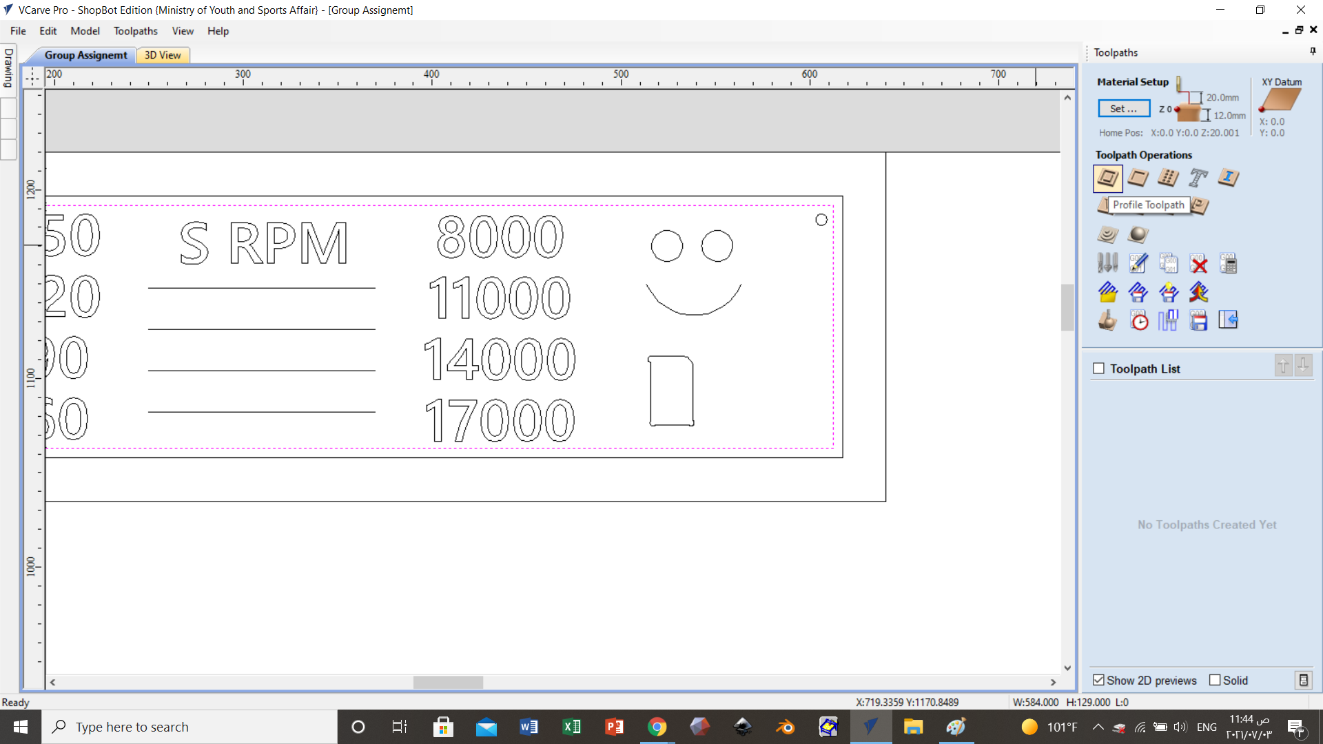
Vcarve’s interface, from which we will perform important operations such as setting tabs and dog bone fillets.

Drilling parameters
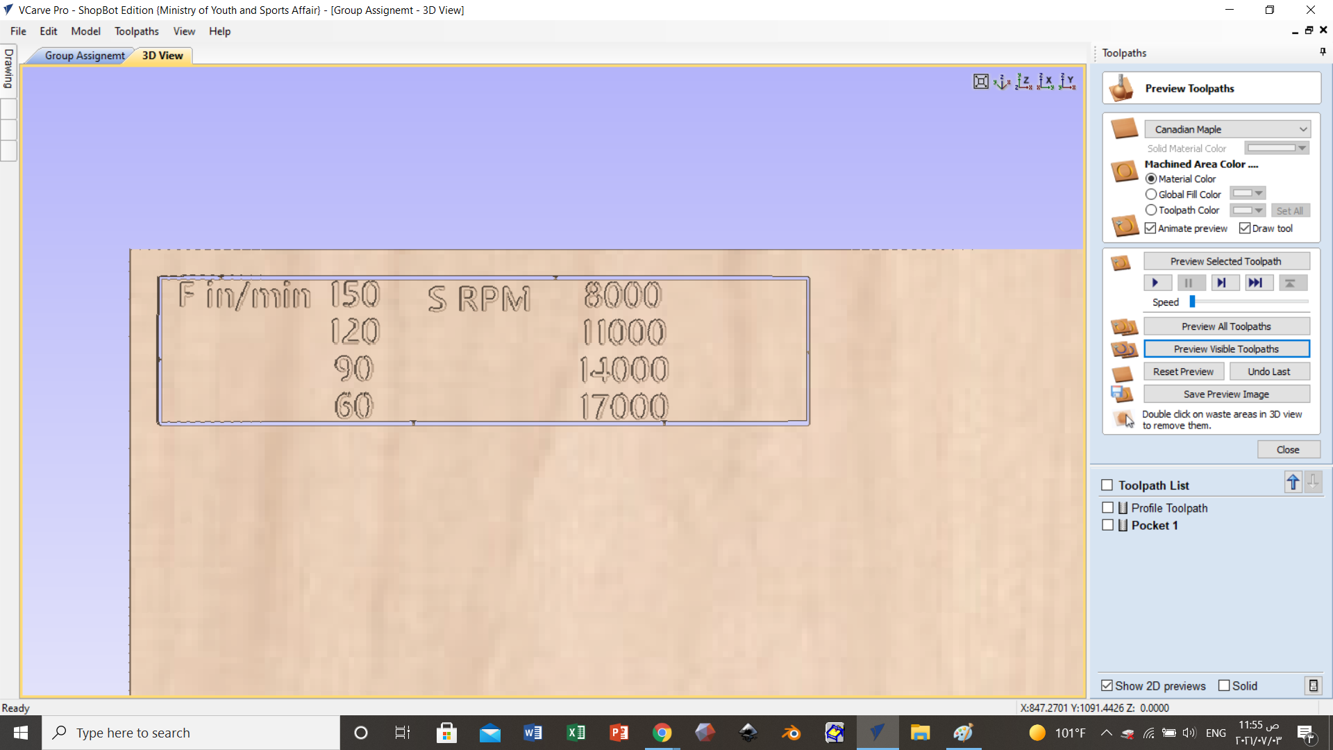
vCarve also include the ability to simulate cuts
I also used the internet to look up an indepth guide on the usage of VCarve. Credits to CNC Routers, Beginners & Beyond - Garrett Fromme on Youtube
Finally, we get to the cutting part. An important step to perform here is calibrating the machine to the starter point. The software features controls to aid in that process. One thing worth mentioning here is that to calibrate the z axis, the machine includes an aluminium piece that must be in contact with the drill surface to configure the zero point of the z axis. This is done through manually lowering the drill.
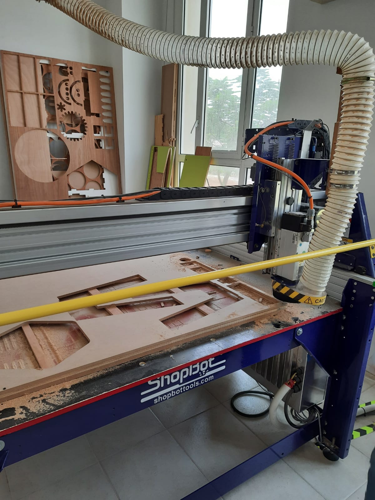
Moving on to the machine itself, there are several parts worth noting. There are two safety switches, one on the side and one by the computer with the software installed, and they’re used to forcefully stop the machine in case of emergencies. The machine is composed of a stationary table like body, and a moving drill which performs the cutting. Turning on the machine requires turning on two switches on the side. The machine also features a vacuum like cleaner that mainly vacuums the chips resulting from the cutting. The vacuum extends into the machine through a rather thick tube, although the main part of the vacuum is in the corner of the room rather than being on the machine itself.
Naturally, safety is of utmost importance during the cutting process due to potential dangers. Safety glasses are a must to protect the eyes from the drill potentially breaking and possibly being thrown out at a massive speed. Operators must also take note of their clothing, as long collared clothes can easily get stuck into the machine. Similarly, this can happen to long hair as well so hair must be tied.
Once the cutting process is done, the parts can be safely removed and cleaned by the operators after turning off the machine. Tabs must be destroyed to facilitate removal, and files are used to clean them out. After that, parts can be properly attached to each other assuming the dimensions and tolerances were correct.
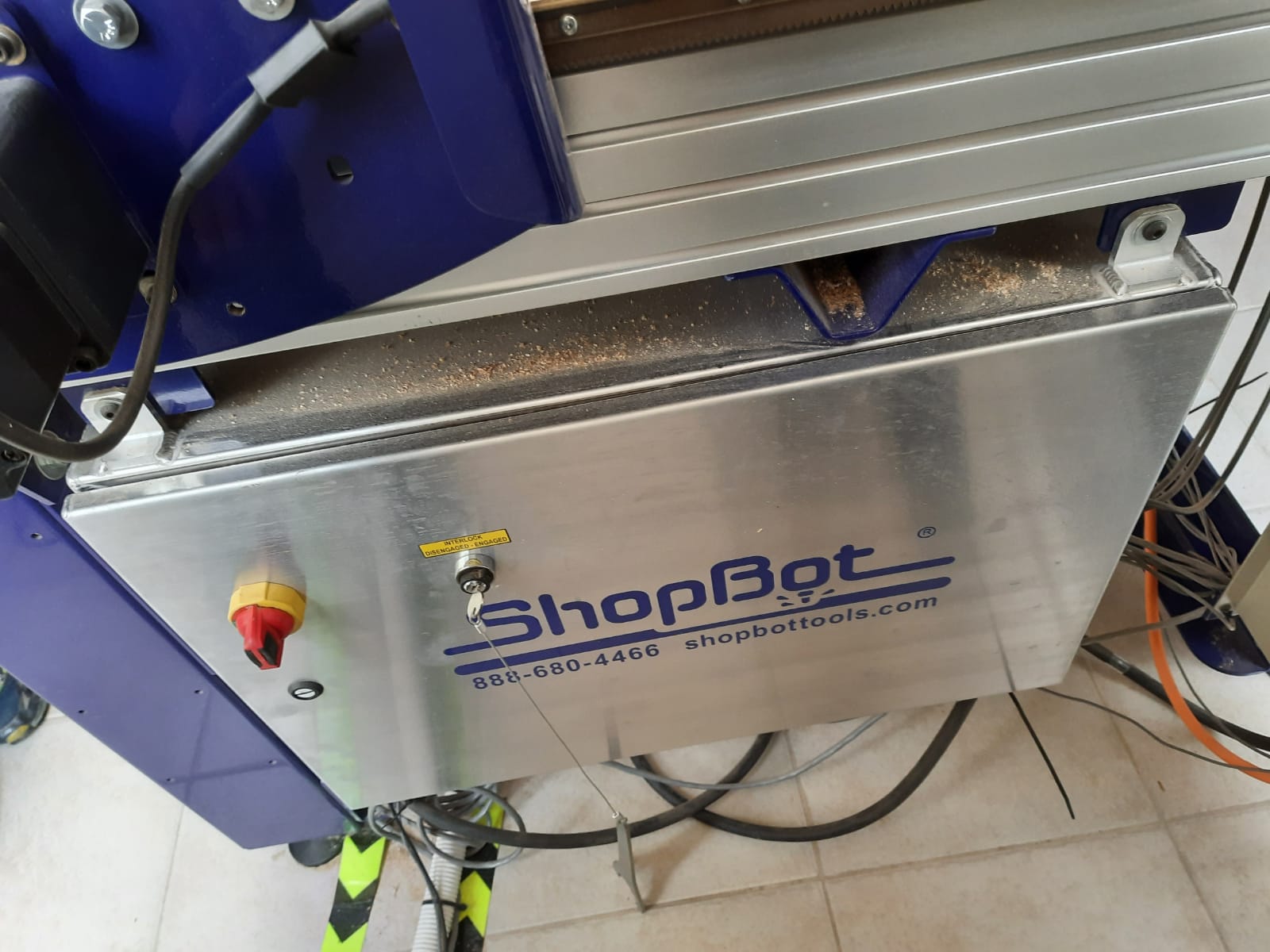
Starting the CNC machine requires turning on the switch and pressing the red key
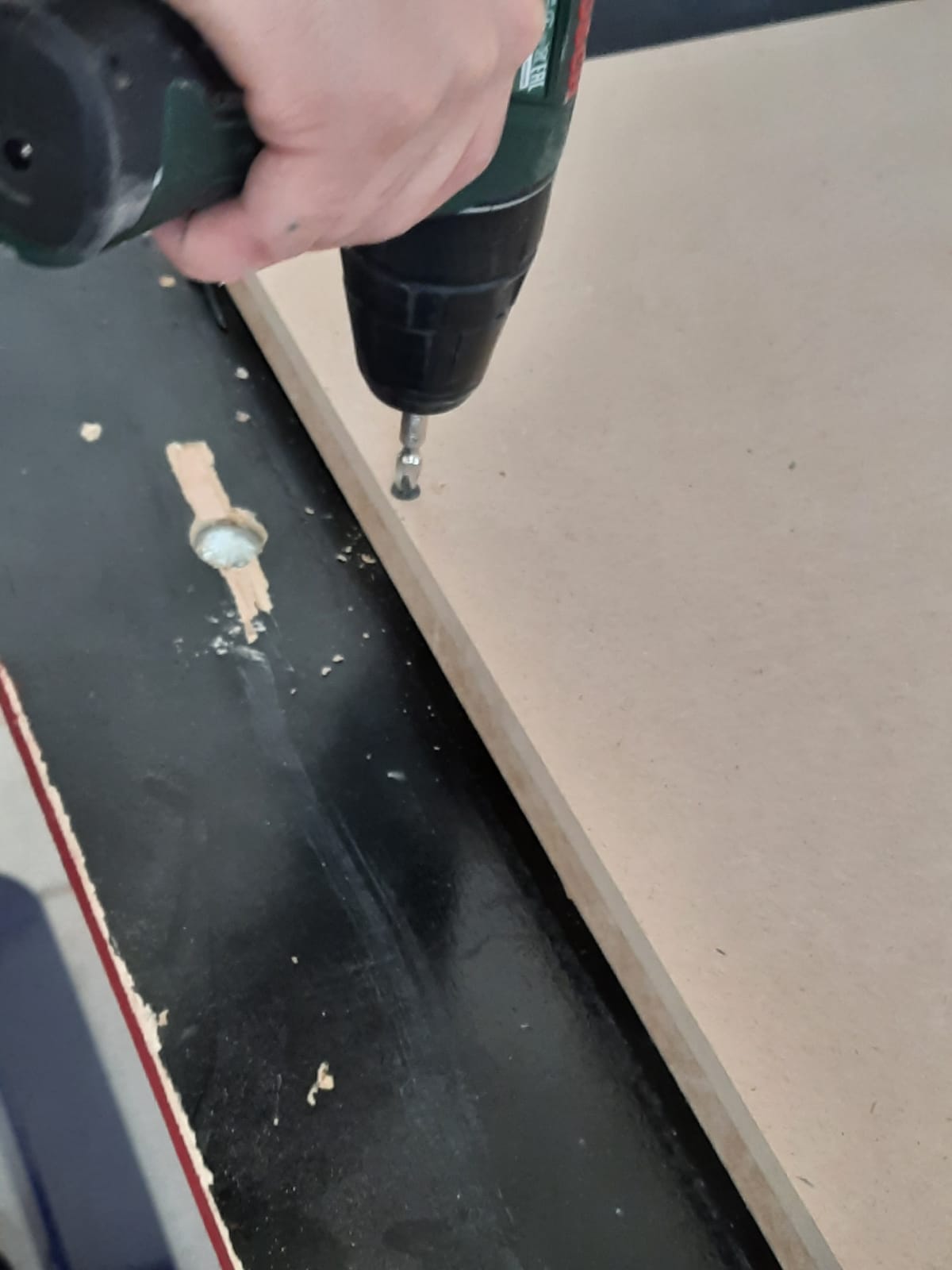
Here we drill the sheet to be cut on another sheet known as the sacrifice sheet for stability
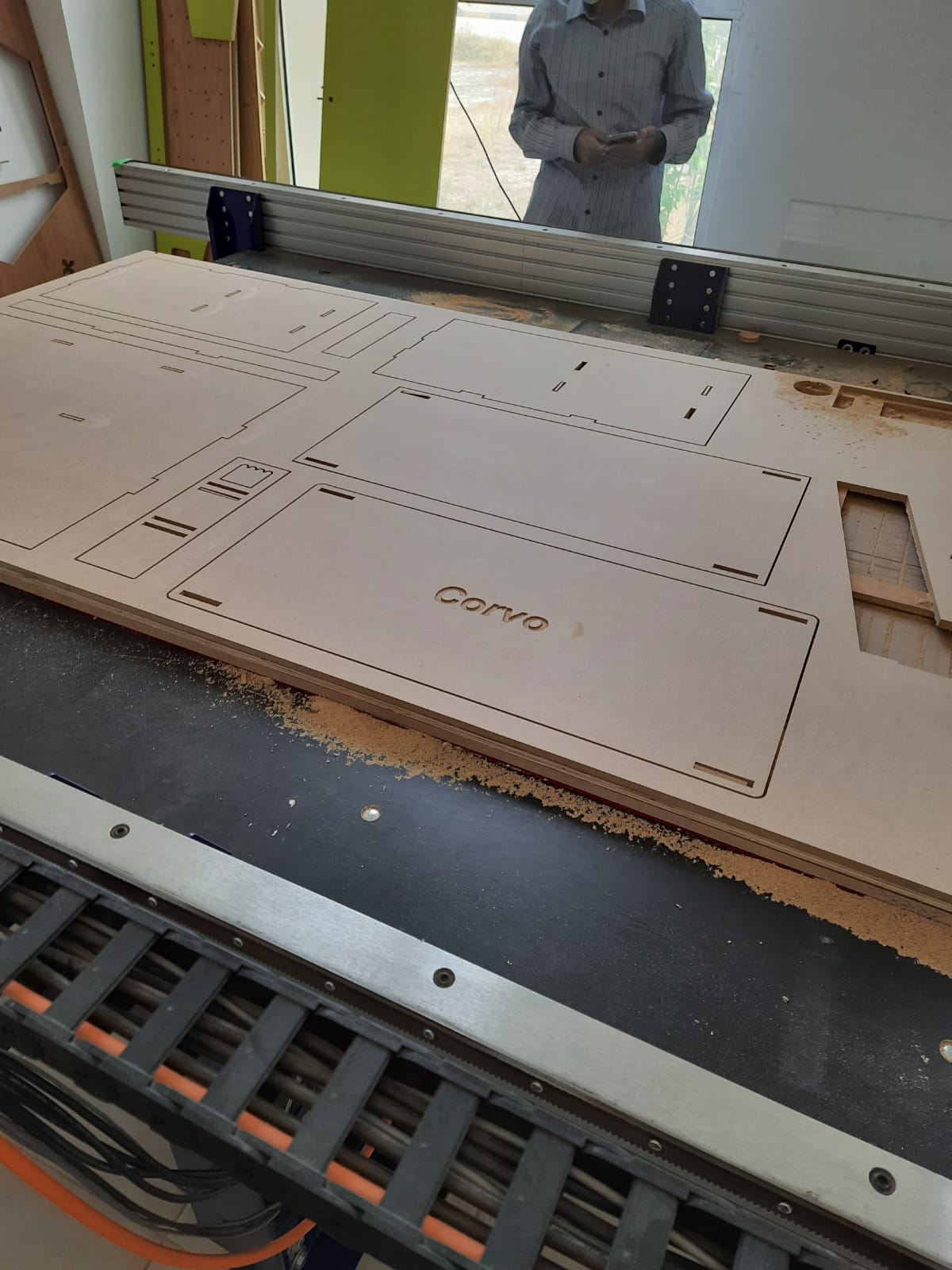

Images of finished products

Tabs we created during the design process to stabilize the cut
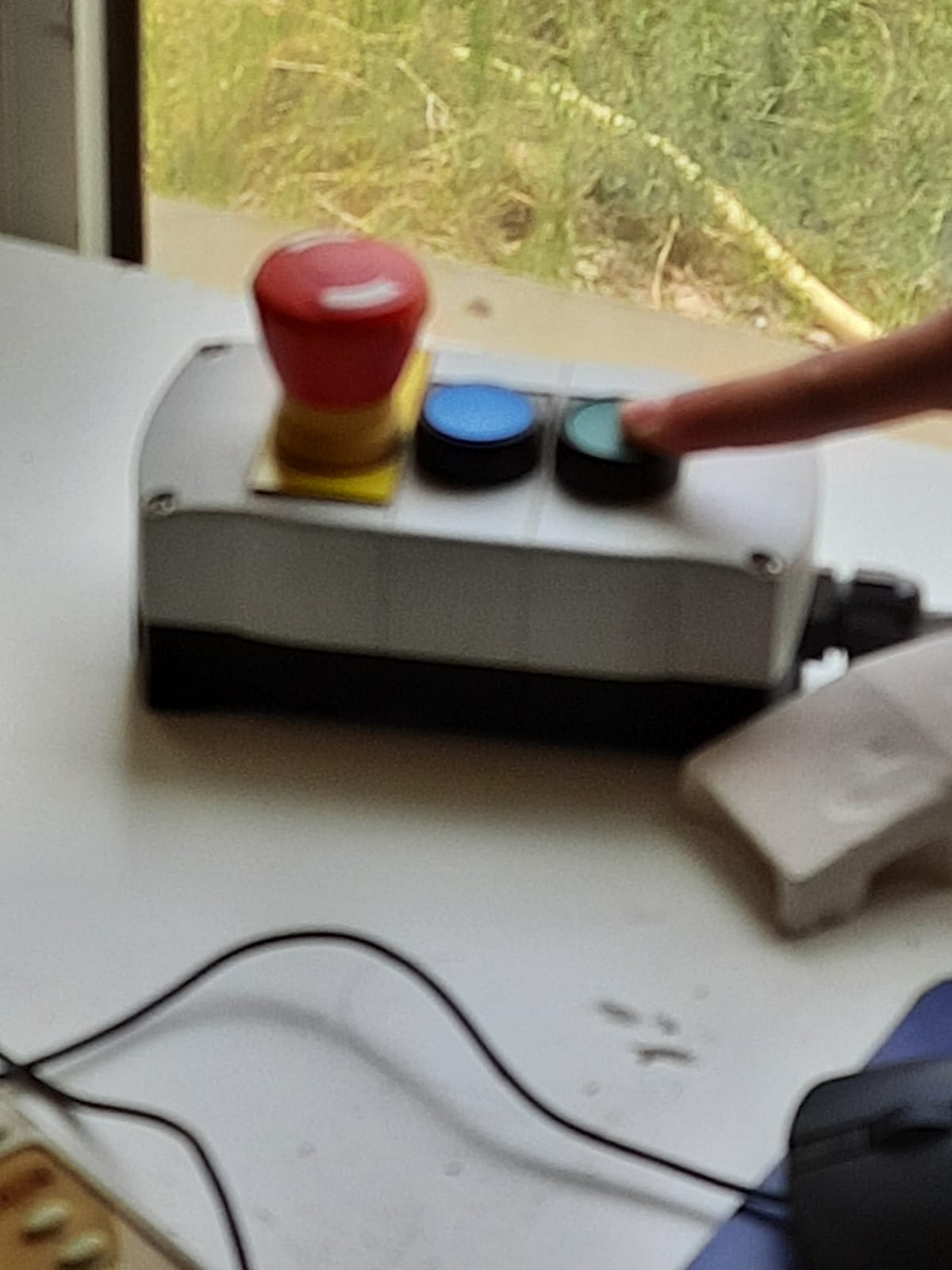
Safety switches for safety
This video is a demonstration of the CNC machine, and the possible designs that can be created Credits to Илья Буката on YouTube