7. Input & Output device
This week was all about inputs and outputs using the microcontroller board.
I’ve tried several sensors and output devices, let’s talk about them one by one.
Temperature and Humidity sensor
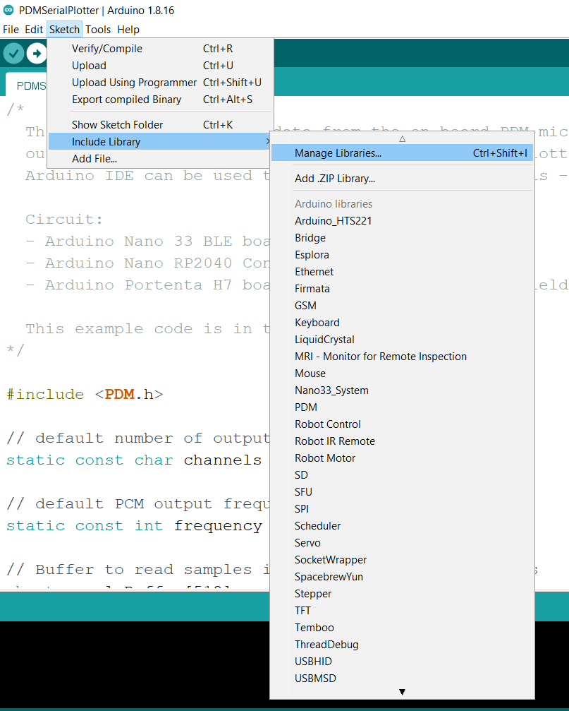
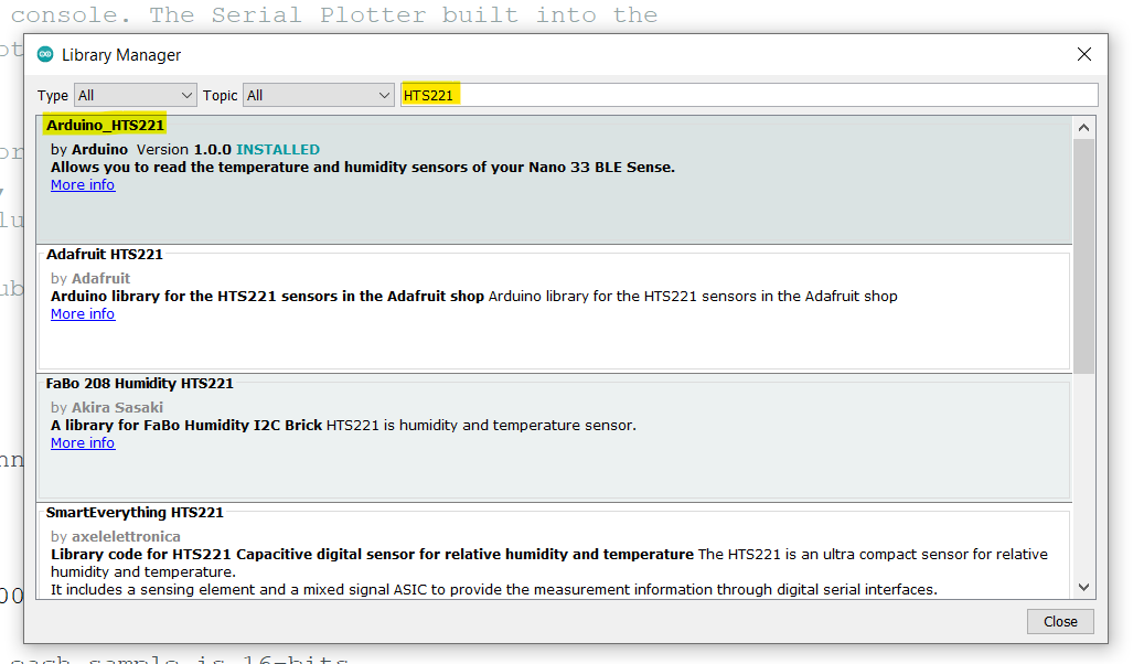
This is one of the embedded sensors in Arduino Nano 33 BLE sense, “HTS221”. To use it, it needs to download its library:
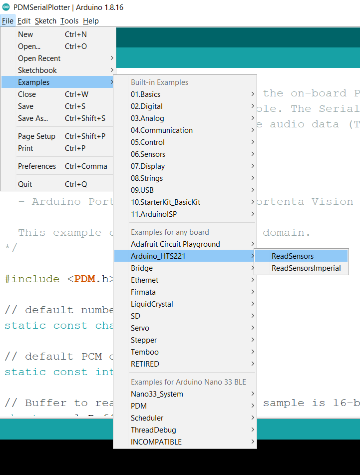
Then use the example code:
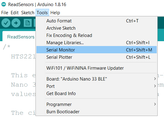
Then, upload it to the board. And open the Serial Monitor:

This was how to use Temperature and Humidity sensor to give me outputs, which they are temperature and humidity value.
KY-009 RGB Full Color LED
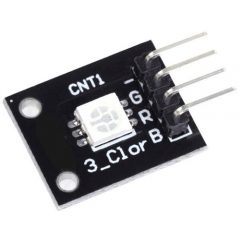
I’ll use inputs from Temperature and Humidity sensor to make control the output of this LED. But before that, I’ll show you first how to use it first. I used a code from the internet to check if it works and not, and in the same time see how it works. See this code:
int redpin = 11; //select the pin for the red LED
int bluepin =10; // select the pin for the  blue LED
int greenpin = 9;// select the pin for the green LED

int val;

void setup() {
  pinMode(redpin, OUTPUT);
  pinMode(bluepin, OUTPUT);
  pinMode(greenpin, OUTPUT);
  Serial.begin(9600);
}

void loop()
{
  for(val = 255; val > 0; val--)
  {
    analogWrite(redpin, val);  //set PWM value for red
    analogWrite(bluepin, 255 - val); //set PWM value for blue
    analogWrite(greenpin, 128 - val); //set PWM value for green
    Serial.println(val); //print current value
    delay(1);
  }
  for(val = 0; val < 255; val++)
  {
    analogWrite(redpin, val);
    analogWrite(bluepin, 255 - val);
    analogWrite(greenpin, 128 - val);
    Serial.println(val);
    delay(1);
  }
}
Okay, but how it works? Simply, it has 3 pin to get voltage from them, the value of each pin determine the percentage of each color (Blue, Red and Green). Every color you can see can is combined by Blue, Red and Green (with different ratio).
Let’s go to our goal. I want to use the inputs from Temperature sensor to use them here. I code it such that, after a certain temperature the LED becomes red, otherwise green.
#include <Arduino_HTS221.h>

int greenpin = 10; //select the pin for the green LED
int redpin = 11;// select the pin for the red LED
int bluepin =9; // select the pin for the  blue LED

int val=255;

void setup() {
  pinMode(redpin, OUTPUT);
  pinMode(bluepin, OUTPUT);
  pinMode(greenpin, OUTPUT);

  Serial.begin(9600);
  while (!Serial);

  if (!HTS.begin()) {
    Serial.println("Failed to initialize humidity temperature sensor!");
    while (1);
  }
}

void loop() {
  // read all the sensor values
  float temperature = HTS.readTemperature();

  if (temperature > 27.0){
    analogWrite(greenpin,0);  //set PWM value for green
    analogWrite(redpin,val); //set PWM value for red
    analogWrite(bluepin,0); //set PWM value for blue
    Serial.println("High");
  }

  else {
    analogWrite(redpin,15);  //set PWM value for red
    analogWrite(greenpin,71); //set PWM value for green
    analogWrite(bluepin,135); //set PWM value for blue
    Serial.println("Low");
  }


  // print each of the sensor values
  Serial.print("Temperature = ");
  Serial.print(temperature);
  Serial.println(" °C");

  // print an empty line
  Serial.println();

  // wait 1 second to print again
  delay(1000);
}
See here how it works!:
This could be enough for this week assignment, but I thought of something more. What if I make a Morse code by Buzzer (or Piezo speaker) and use the embedded digital microphone in the board to translate this Morse code, and print the results on a LCD display. This would be insane if I can do it, but anyway, I’m here to show what I learned in trying to do it.
Buzzer (Piezo Speaker)
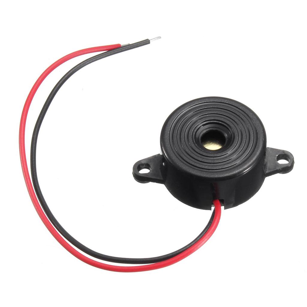
At first, what is a buzzer?
A buzzer or beeper is an audio signaling device, which may be mechanical, electromechanical, or piezoelectric (piezo for short). Typical uses of buzzers and beepers include alarm devices, timers, and confirmation of user input such as a mouse click or keystroke. (Wikipedia)
To use it, I build on a simple code I got it from Arduino Project Hub, then I build on my previous code to make a Morse code from week04 (Embedded Programming). So here is the resultant code:
const int buzzer = 9; //buzzer to arduino pin 9

void setup(){
  pinMode(buzzer, OUTPUT); // Set buzzer - pin 9 as an output
}

void loop(){
  // K:
    dash(); gap(); dot(); gap(); dash(); letterGap();
  // U:
    dot(); gap(); dot(); gap(); dash(); letterGap();
  // M:
    dash(); gap(); dash(); letterGap();
  // A:
    dot(); gap(); dash(); letterGap();
  // I:
    dot(); gap(); dot(); letterGap();
  // L:
  dot(); gap(); dash(); gap(); dot(); gap(); dot(); letterGap();
}

//Define functions:
void dash(){tone(buzzer, 1000);delay(1*1000);}
void dot(){tone(buzzer, 1000);delay(0.5*1000);}
void gap(){noTone(buzzer);delay(0.5*1000);}
void letterGap(){noTone(buzzer);delay(2*1000);}
The code is correct and work properly, but the buzzer itself sometimes make some weird noise. That’s about Buzzer.
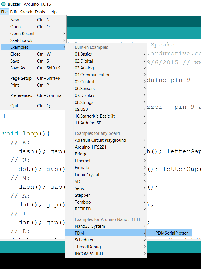
Digital Microphone
I didn’t do anything here amazing, I just upload the only example code from the library:
To be honest, I didn’t understand it at all, just upload it and see the Serial Plotter. Here is an example of what the serial plotter would show you (I got it from internet):
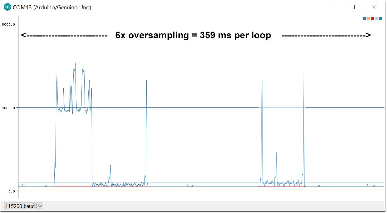
Here you can see more about serial plotter and know more about it in Arduino get started website.
Fine! I can say that I checked 2 out of 3 of the devices I need to make idea real.
LCD JHD 162a
This is the LCD display I tried to use:
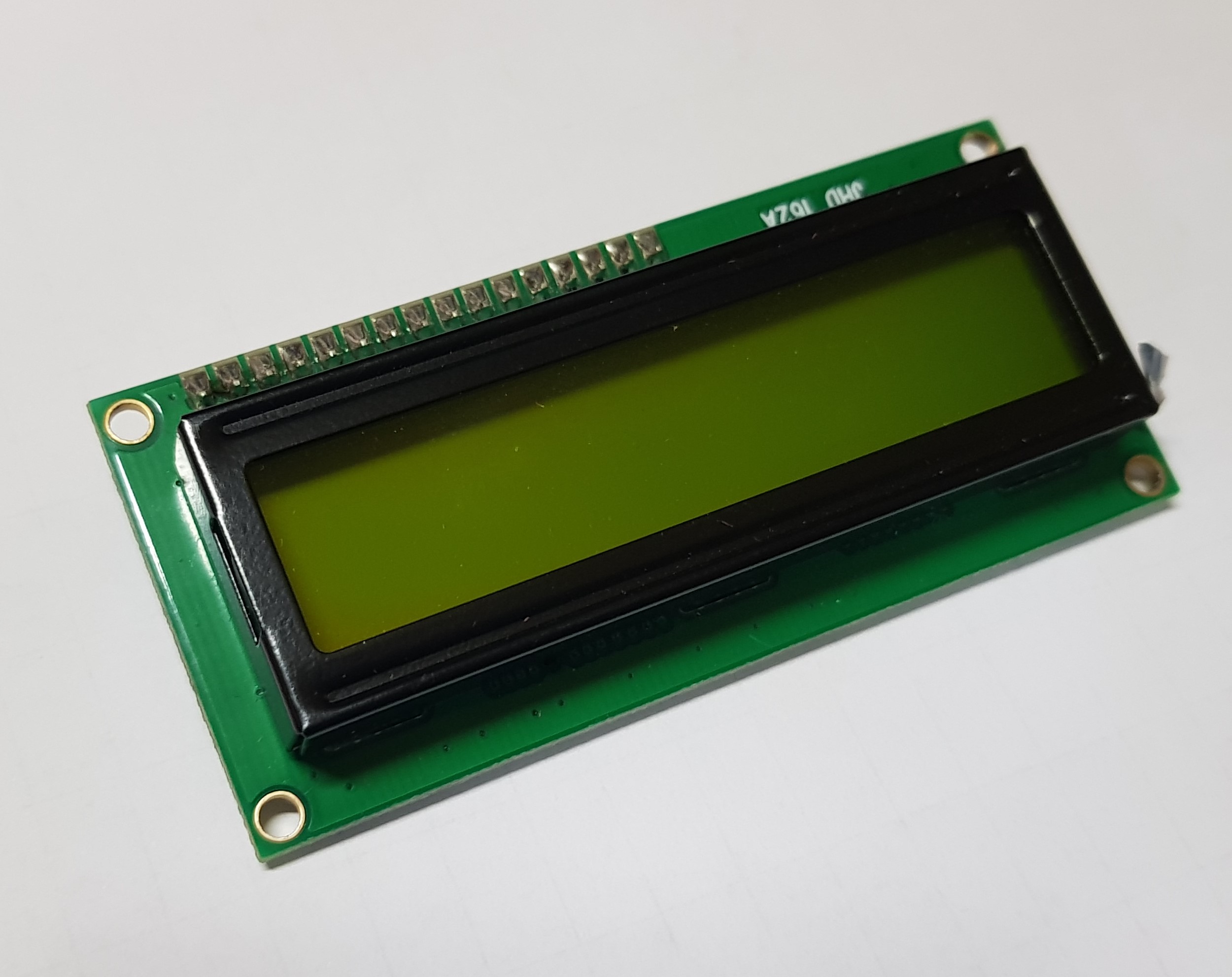
See it’s datasheet here.
It has its own library, and there are examples for it:
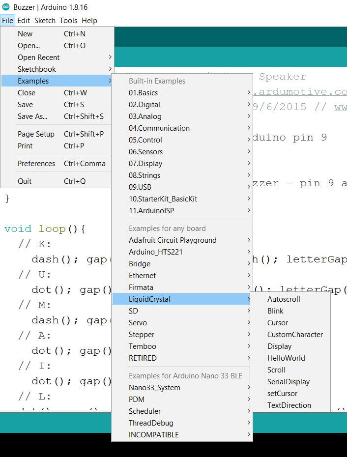
That seems good, but wait, as you see in the datasheet it has 16 pins need to be connected with the board. It needs a lot of jumper wires, and a resistor. This is not easy to use for a beginner, so there is something make it easier.
I2C Module
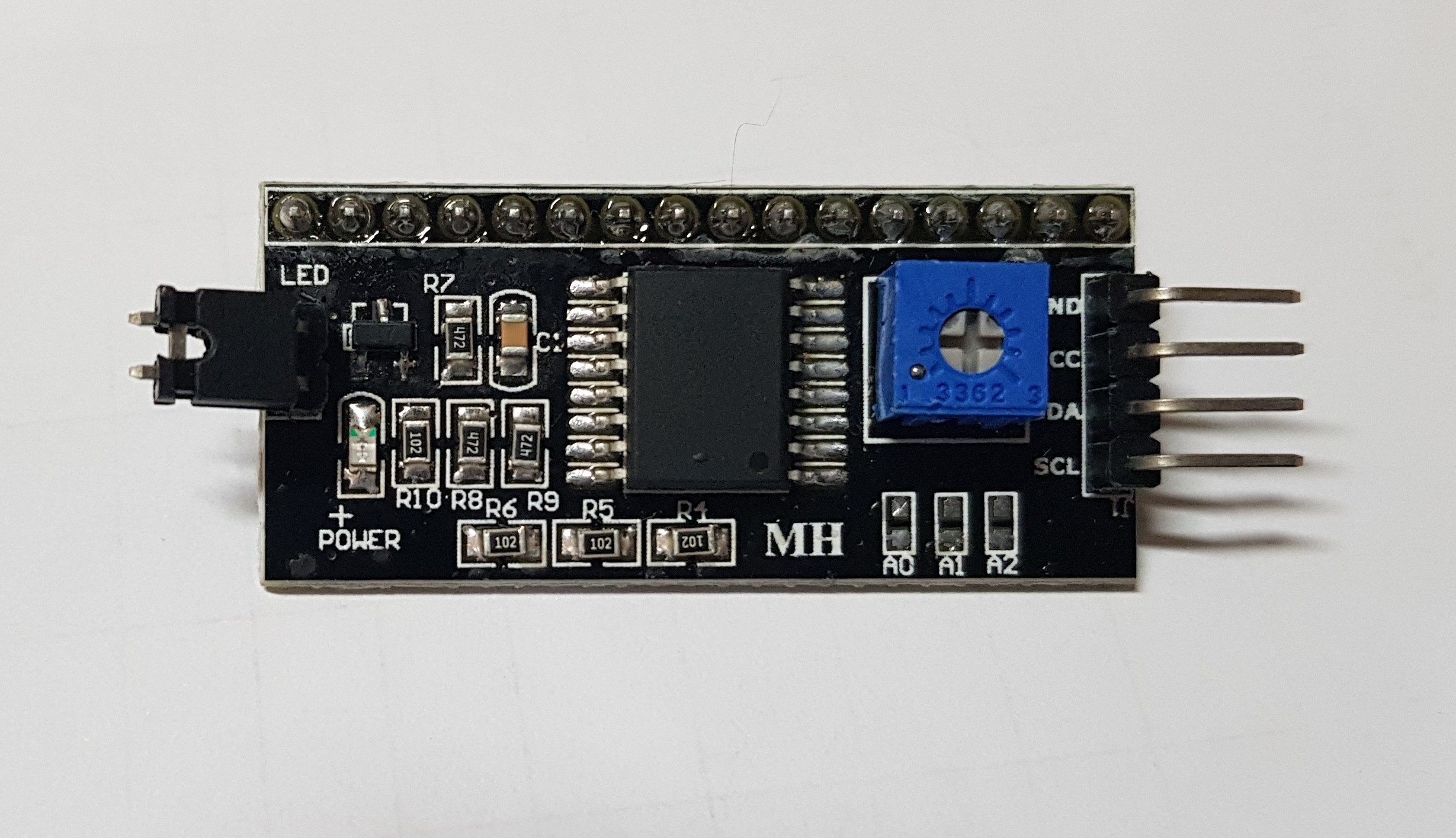
This I2C module is connected in parallel with all pins of LCD, and left to us 4 pins to connect with the board. This sounds great!
The connections was fine for me, but the problem I face is that I don’t what is the library I should use (It uses another library than the LCD one).
So I stopped here, for sure I’ll try to do this idea. It would be great then!
My view:
Here I’ll write about my point of view, on my progress this week.
At first, I see that as more devices are used, the more mess of jumper wires. This makes it difficult to spot where is the error in code or connected wires. For that, I prefer and recommend to use a breadboard. It makes life easier and clean.
Also, by going through Arduino libraries, the coding language becomes more advanced, and not easy to understand for who have a basic programming background. You can simply use someone’s else code or example codes, but you can’t edit it easily to fit your wants. So I encourage you (and myself also) before using ready codes, try to understand how it works what are functions they used and you don’t know about them. This way you can improve your skills!
Another point, it’s useful to read about the device you are using. This makes you aware of the ability of your device, its limits, and so on. By this, your ability to choose the perfect device for your needs.
That’s all.