Final Project: MAZE RACE
In the following sections me and Sayed Ali will show our project idea and how did it and how did we overcome the obstacles we faced.
What is MAZE RACE?
MAZE RACE is our project’s name. Our idea is to make a manual maze that counts the time you takes to solve it. You can compete with friends to achieve the least time!\ Also, you can play it with countdown mode. Can you solve the maze before time’s up? This is up to your skills!\ We should say, our maze is modular. If you beat it once, we’ll change to difficult one.
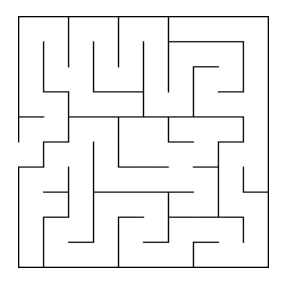
The design of maze is taken from this maze generator. We chose it 10×10 maze, and here is what we used:
Design and digital fabrication
Design
Most of things we fabricate was designed by us. Starting from platform to the cap of electronics part. And all designs are parametric.
1. Platform and outer walls
The platform and outer walls have be designed following a tutorial for making a box with finger joints.
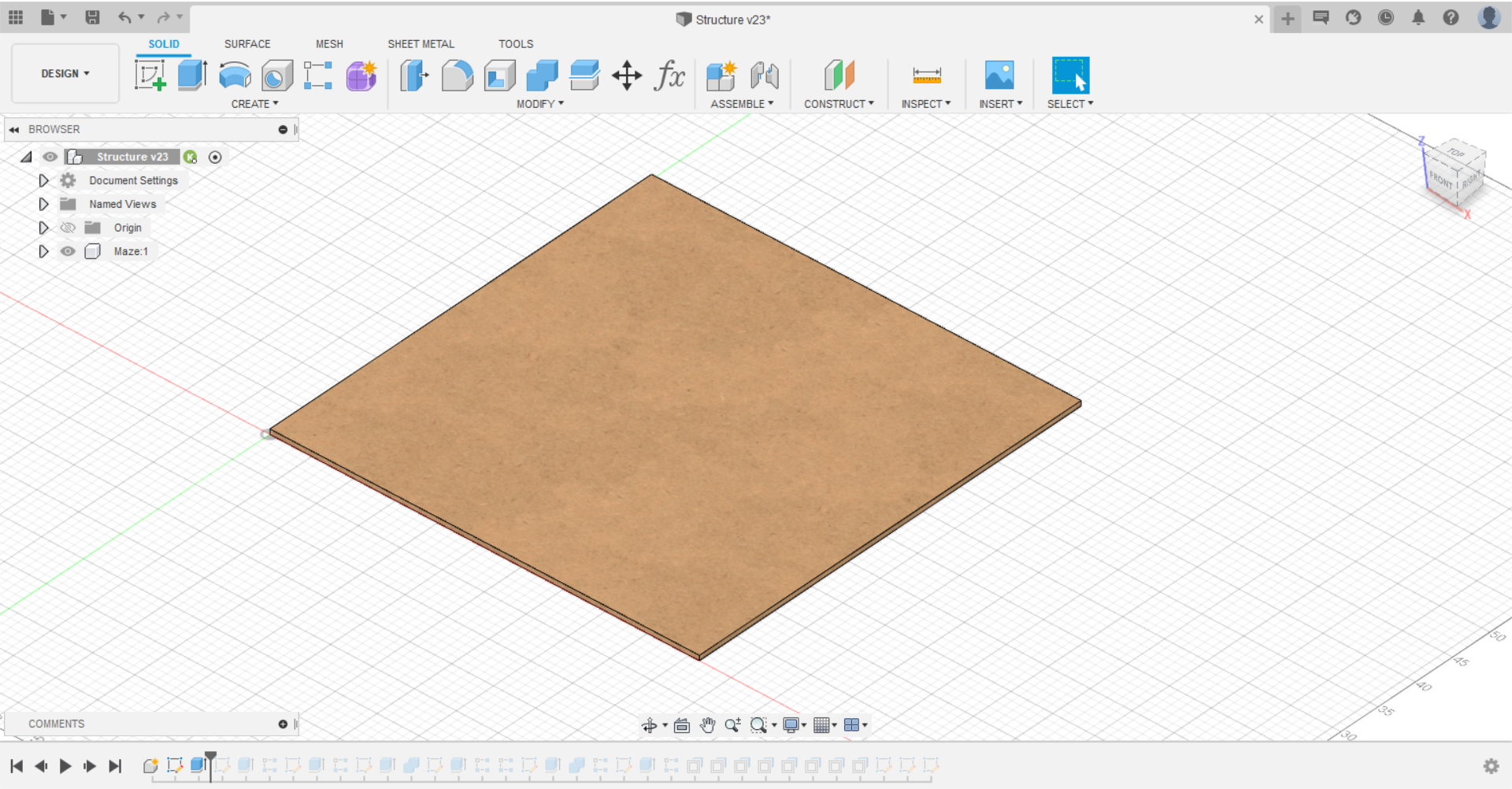
First make a sketch and extrude it:
Then make the finger joint on two sides then mirror them on the corresponding sides to them. The result is:

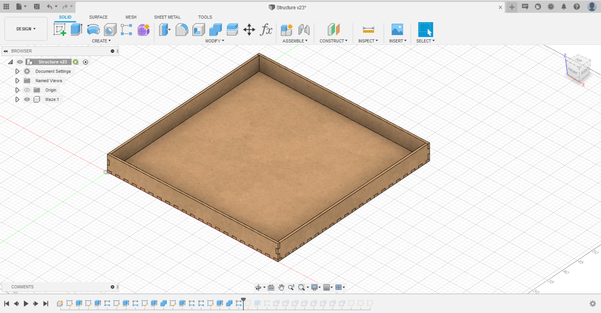
After that make the outer walls, by making a sketch and extrude it, and combine it to cut the duplicated places:
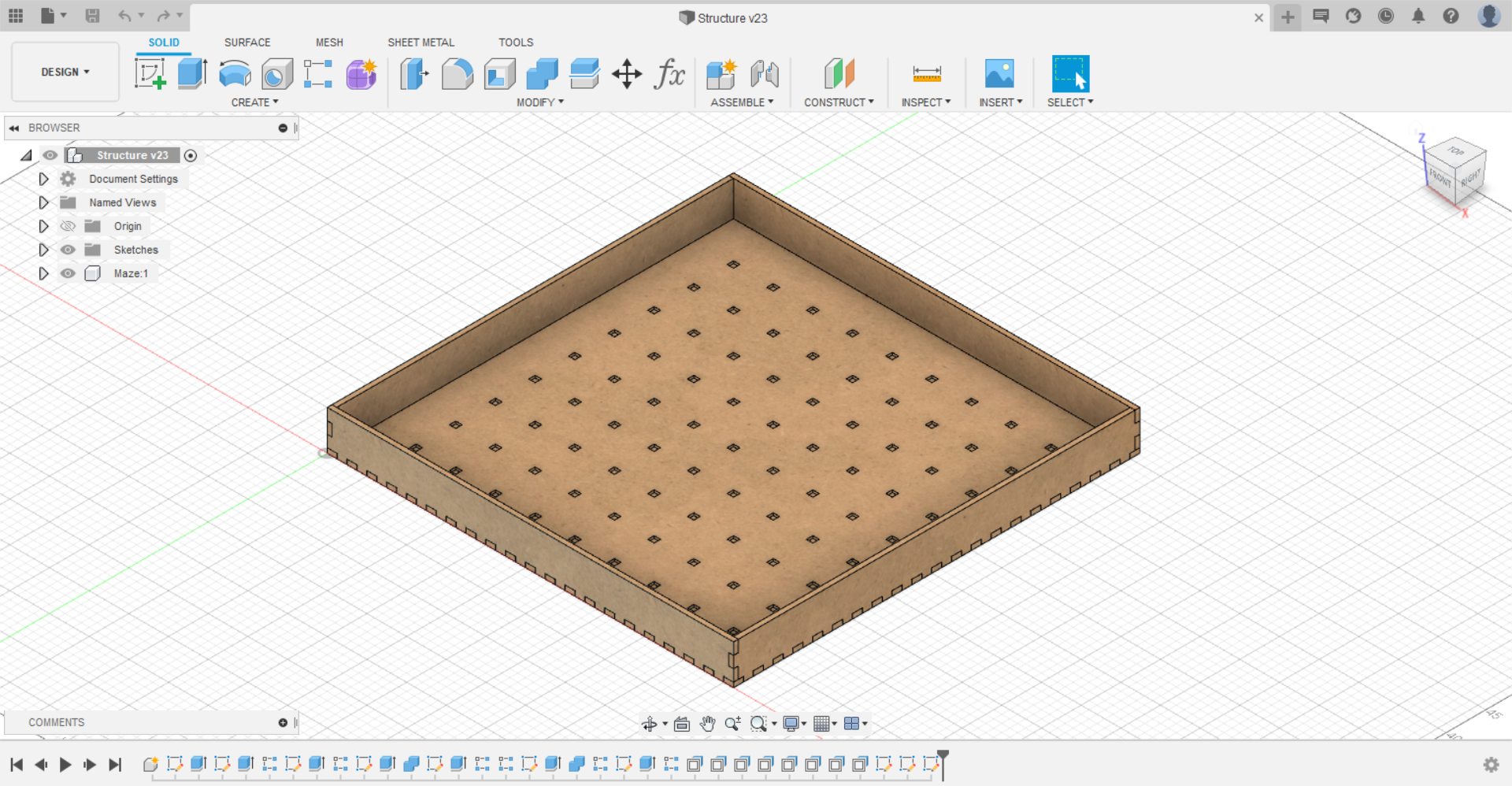
Now, the box is ready. It’s time to make the square holes to put the axles in. Make a sketch, draw the square hole, extrude it through the platform, then expand this feature among the whole platform:

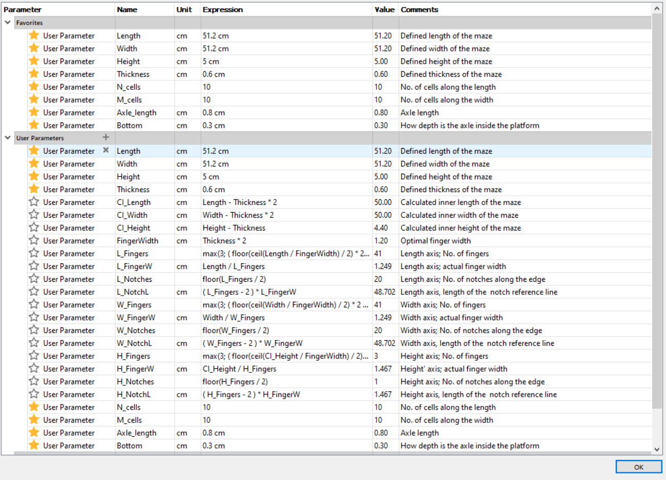
Here is a picture of the parameters used to make the design parametric:
Design is done now, but keep in mind that this is not totally ready to cut it by laser cutter machine.
2. Axles
These are the parts we put in the holes we made in the platform to hold the inner walls. These pieces are inspired by the Lego one used in robotics projects.

Note: the parameters used in axle design is related to the same parameters used before in platform and outer walls.
It is easy to design it. Open a sketch, draw a square, extrude it. The draw another sketch on the top, draw where you want to cut through, extrude it. Add some features, filling or chamfering if you want, see the result:

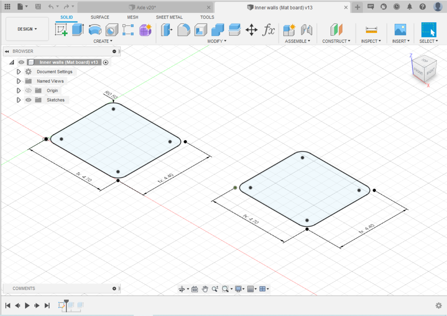
3. Inner walls
This one is also easy to make. Open a sketch, draw the shape of the inner wall you want (a square or ) with the correct dimensions (calculated using the parameters). By this, it’s done:
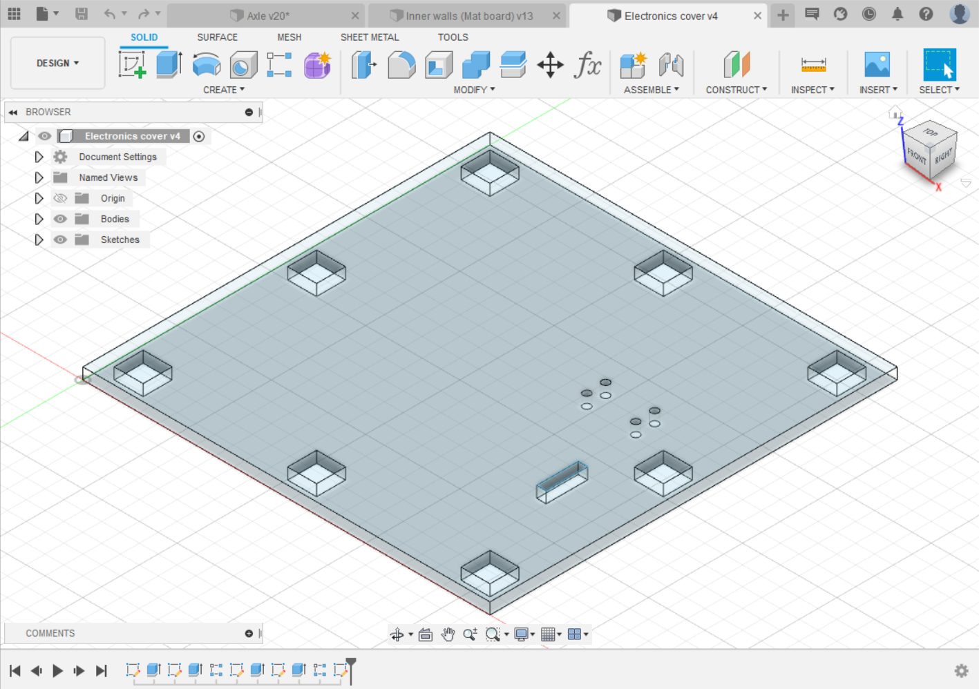
4. Electronics cap
This is cap used to cover the electronic elements, which are placed at the center of the platform. Unfortunately, this design is not parametric.
Designing steps are the same as above. Open a sketch, draw a square with the a length suits the electronics area. Then make small square holes for the axles to fix it. Also add holes for wires connected to the OLED screen and button (No worries you’ll know about then in Electronics section).
Digital fabrication
All designs are ready, it is fabrication time!
Let’s talk about the material used and fabrication method:
| Pieces | Fabrication | Material |
|---|---|---|
| Platform | Laser cut | 3mm MDF wood |
| Outer wall | Laser cut | 3mm MDF wood / 3mm acrylic |
| Inner wall | Laser cut | Matt board |
| Axle | 3D printing | PLA |
| Electronics cap | Laser cut | 3mm acrylic |
The secret behind using two materials for outer walls is that the outer walls is composed of two layers: MDF and acrylic, with total thickness 6 mm.
1. axles
Starting with axles, we need 81 axles. So printing them would take a long time. So we need to minimize the size of axles so we can print them faster.
The first try was using Creality Ender-3 3D printer, this was the result:
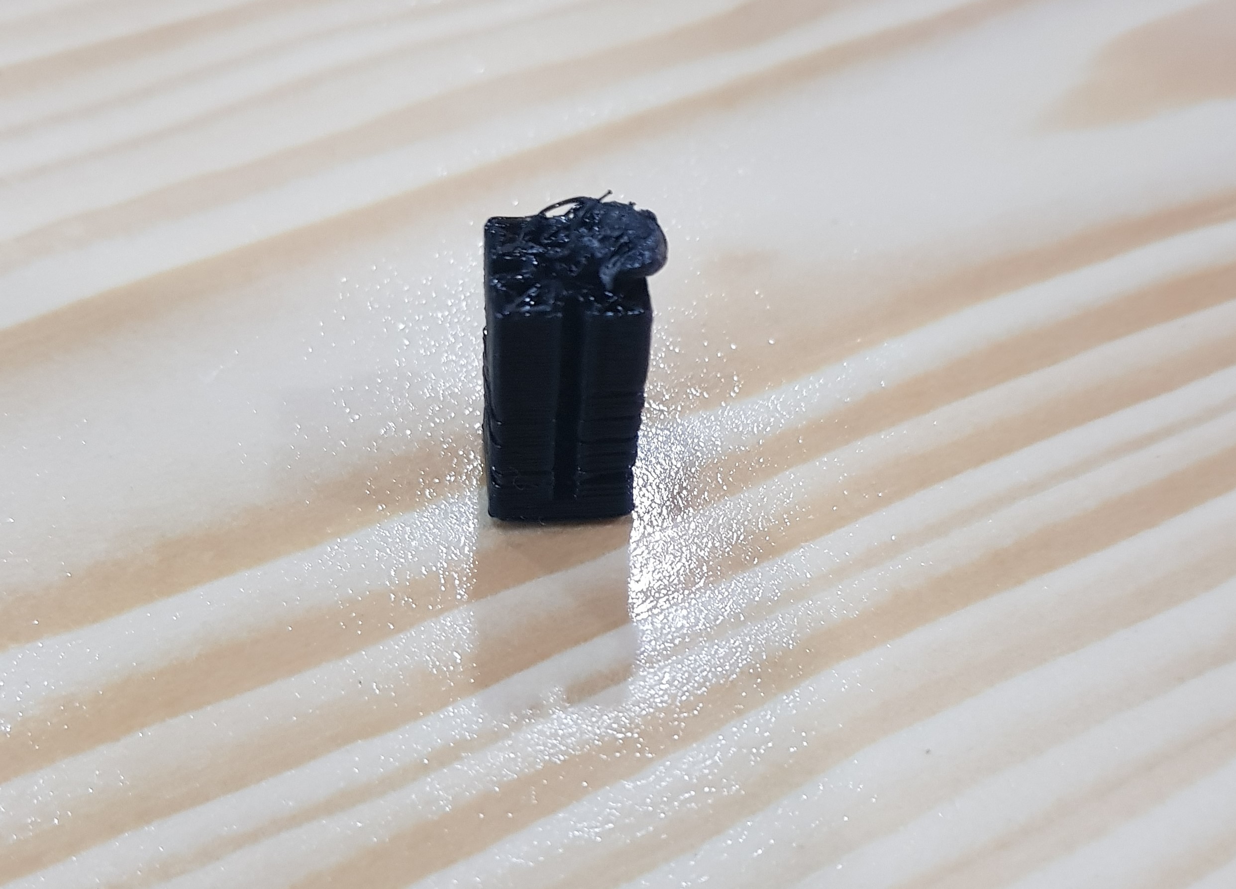
It was like this, because it falls down and make a mess. The solution is to use brim in slicing step.
And there was another mistake, that we didn’t check the filament material, it was ABS, and the settings was for PLA.
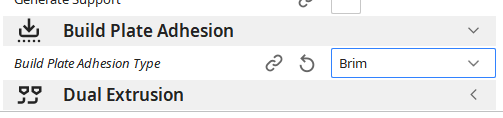
Then, we fix these mistakes and print them this time in Ultimaker 3d printer. We made a test of 2 axles:

It is good! But very tight to insert the inner walls (1 mm thick), and too high. Remember we need to minimize time as much as possible. The second try we widened and increase the depth to insert inner wall, and decrease height to half what it was:
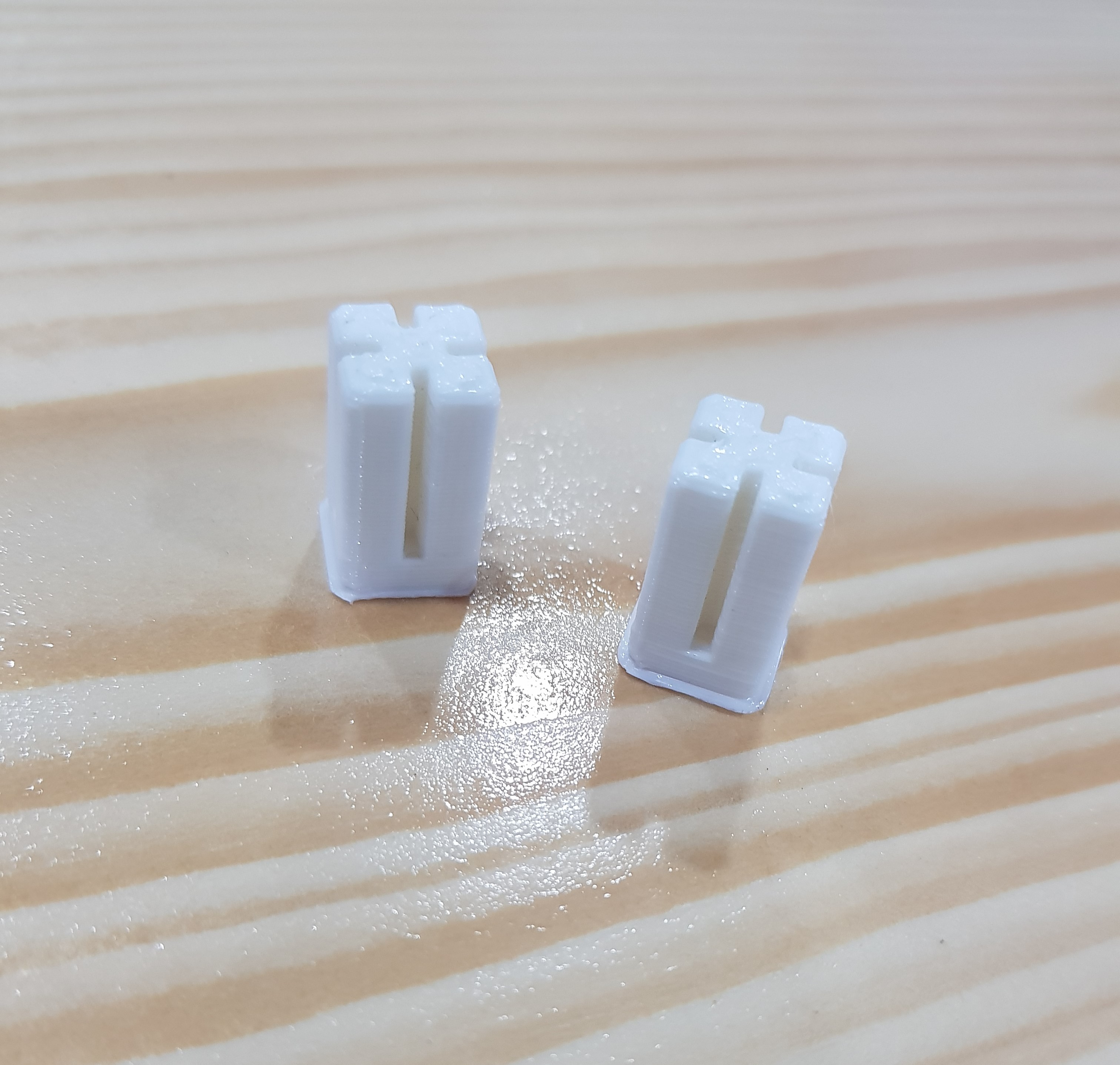
It is too wide, and too short, do you see that?
Now it is better:
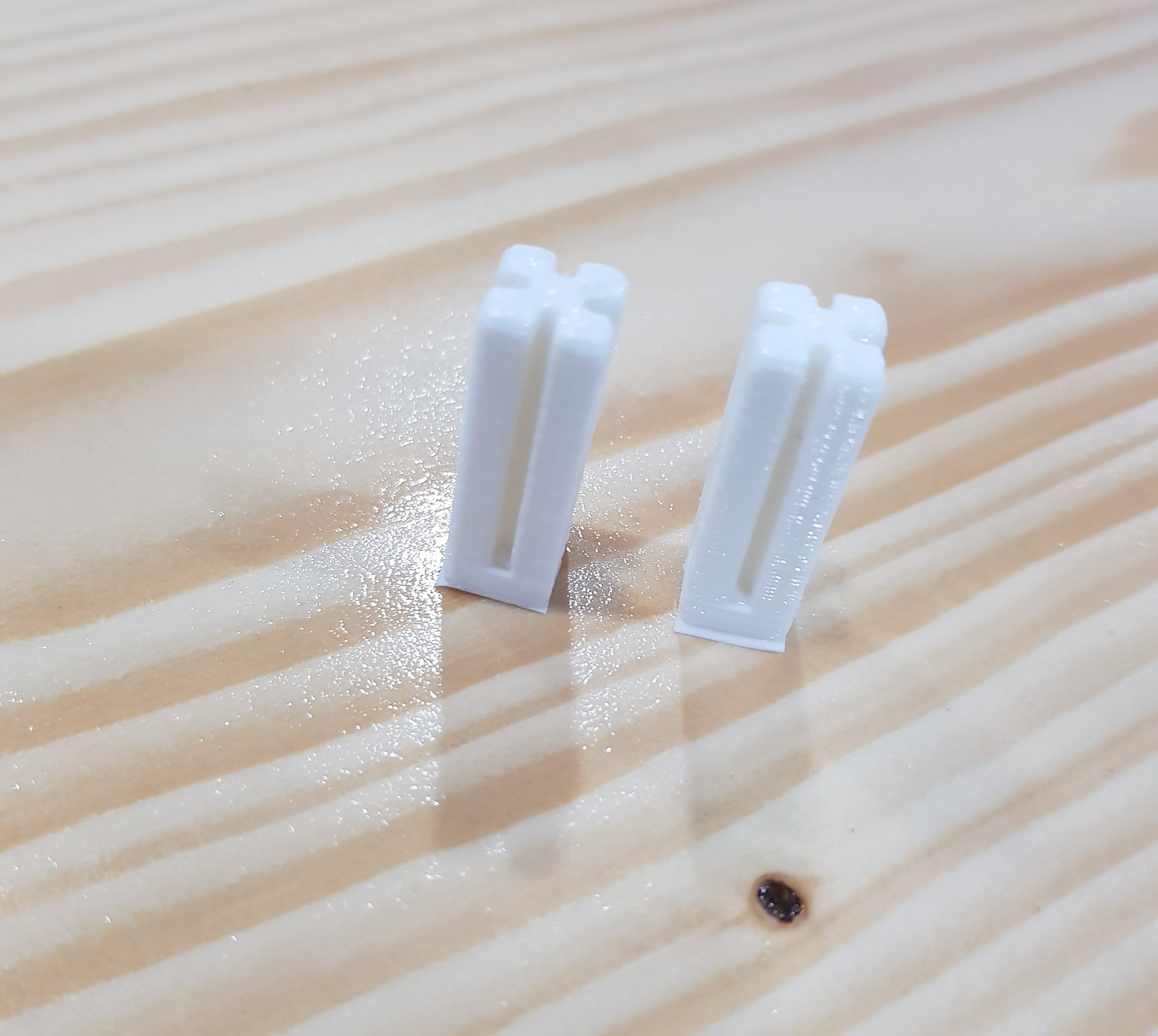
The first 40 axles done:

Left 39, but the story didn’t ends. Unfortunately, because of wrong estimation, in the next 40, the filament wasn’t enough, and is replaced by another filament (with another color). Due to this, the whole 40 weren’t usable because some shift in the nozzle moving while replacing filament:
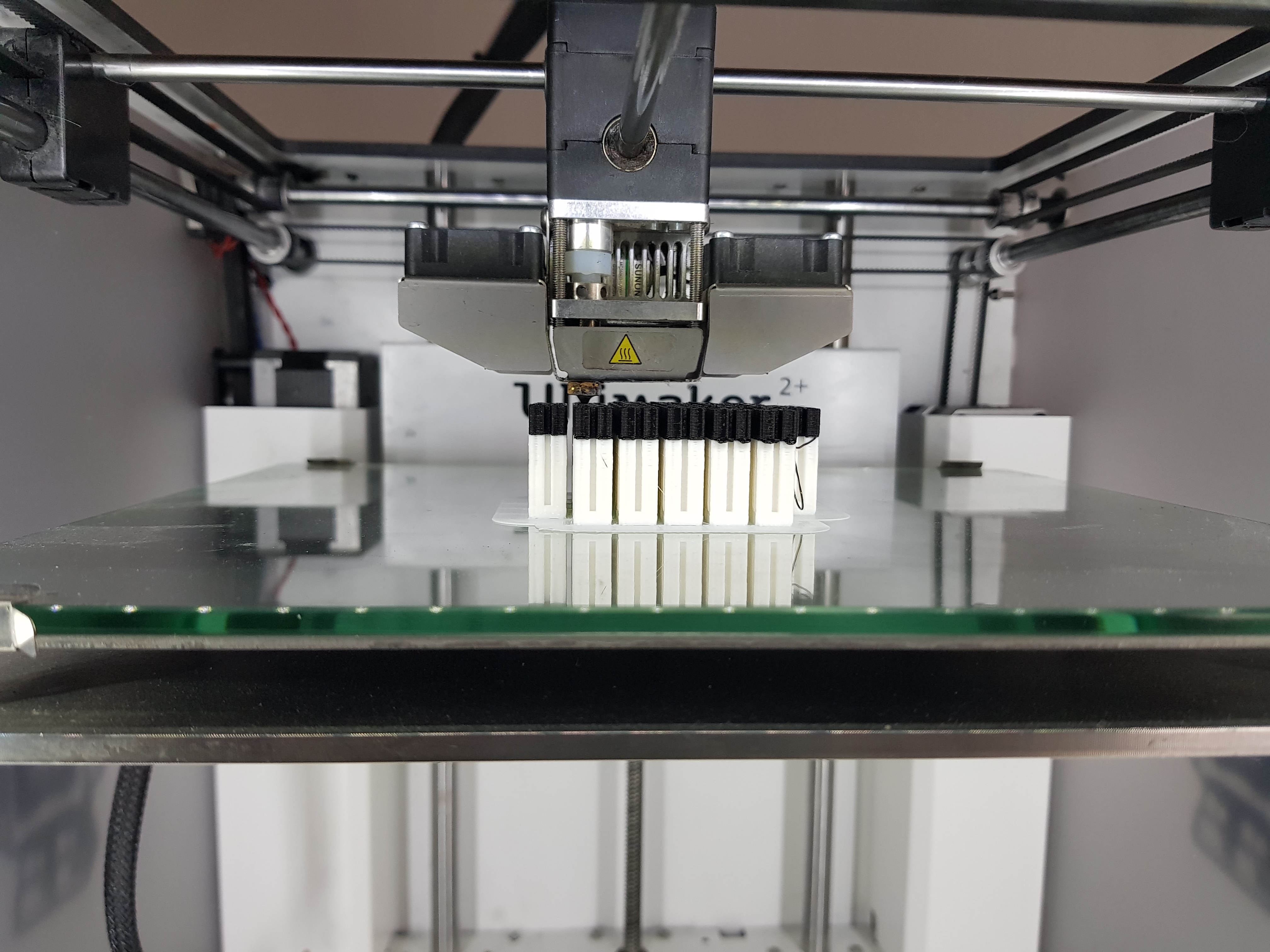
You may say, so what, print more. But notice that we lost time and, there wasn’t enough filament for another 40 axles. So we need to go to another 3D printer. Which has different tolerance, that would make an obstacle we need to tackle later in fitting in the platform.
2. Inner walls
For matt board, we didn’t have the speed and power we should use. So by trial and error, we found that power 30% and speed 20 mm/s is best everywhere in the laser cut machine.

3. Platform and outer walls
We have two things here to test: 1. How axles fits in the holes. 2. How the finger joints fits together.
For the first one, we made a fit test:
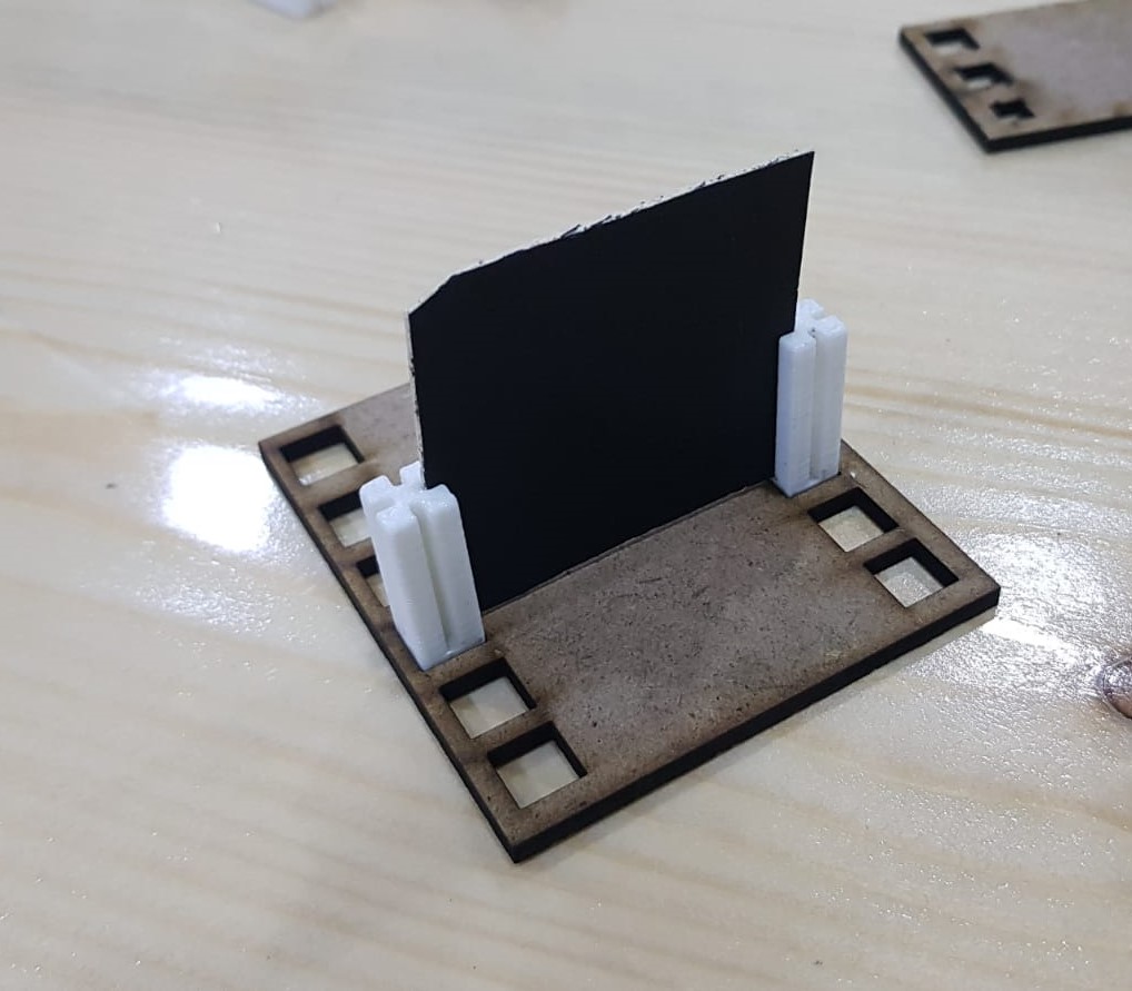
We saw that for an axle with side length 8 mm, the best fit is for the hole side length 7.7 mm.\ This fit test was for the axles made by Ultimaker 3D printer. For other axles, printed by Creality Ender-3, they have different tolerance. We sand-papered them to fit in the holes.
For the second one, we need first to test it on small scale boxes before doing it on the real scale.\ But unfortunately, the box wasn’t fits. This is due to the material burned by the laser through the cutting.\ To fix this, we need to go to the design and set an offset on the finger joints.\ And guess what? It worked!
Electronics
Look at our work on Sayed Ali’s page here.
Assembling
Look at how we assembled it here.
Further implementation
Here what we think to do to implement our project in future.