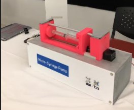
Micro-syringe pump
Micro-syringe pump is a convenient tool for precise injection of fluid in microfluidics applications. We developed this tool for the purpose of inputting fluid in our designed microreactor. We chose to make this project because it combines all the elements we learned in Fab Academy, including but not limited to 3D printing and electronics.
My main task was 3D design and printing, which is the part I will elaborate on, my colleagues Batool and Mahmood worked on incorporating electronic devices to the micro-syringe pump, more information can be found on their websites.
3D design and printing
3D printing is the process of making three dimensional objects from a digital file. It is an additive process. It works by melting plastic filaments and laying down layers of the material on top of each other to form a solid object.
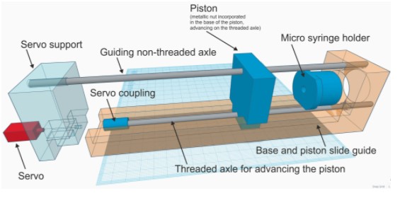
The design was adopted from this website.
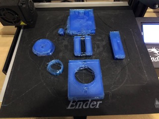
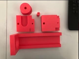
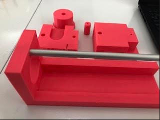
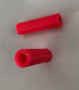
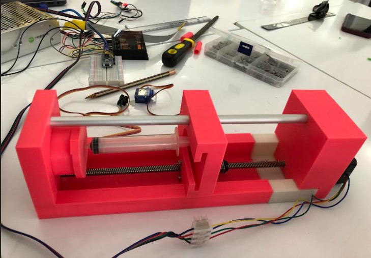
Five parts of the micro-syringe pump were printed, base, servo module support, servo coupling module, piston, and micro-syringe holder.
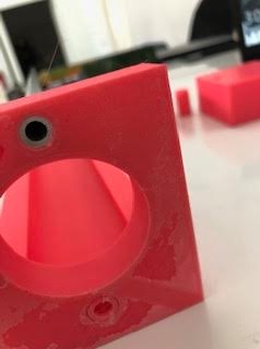
We were given a metal rod of approximately 9.5 mm outer diameter, this rod must be fitted into the base according to the design chosen.
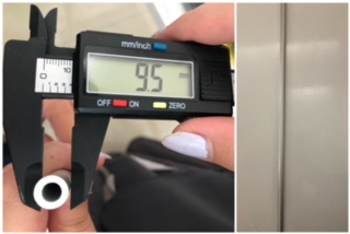
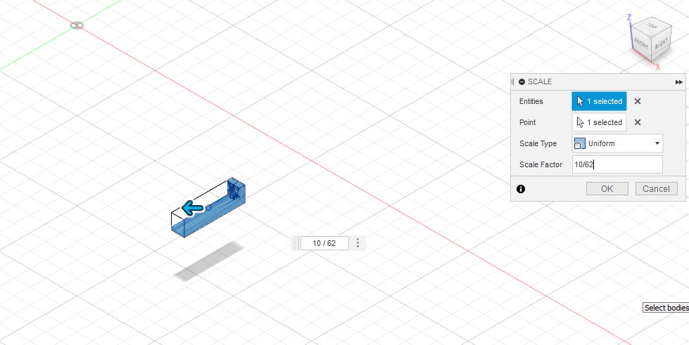
Therefore, I adjusted the diameter of the hole (at the top) in the base to 10 mm, to make sure the rod can fit in. I used Fusion360 to do that
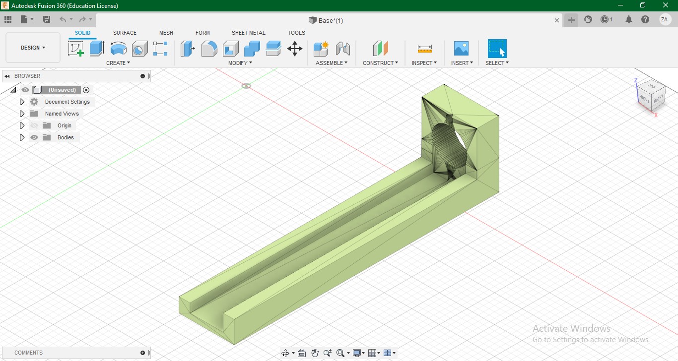
I measured the dimension of the hole, it was 62 mm
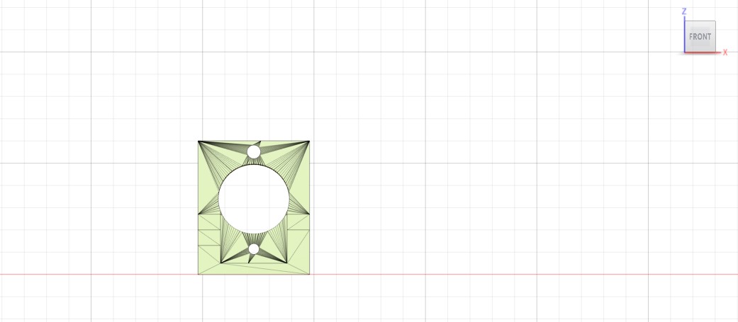
Then, I scaled down the solid by a factor of 10/62 (10mm is the desired diameter)
After scaling down, the length of the base was around 38 cm, the 3D printer would not be able to print an object that big
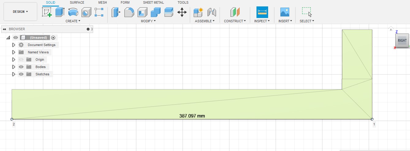
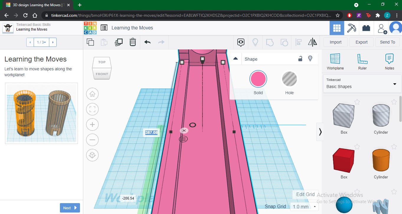
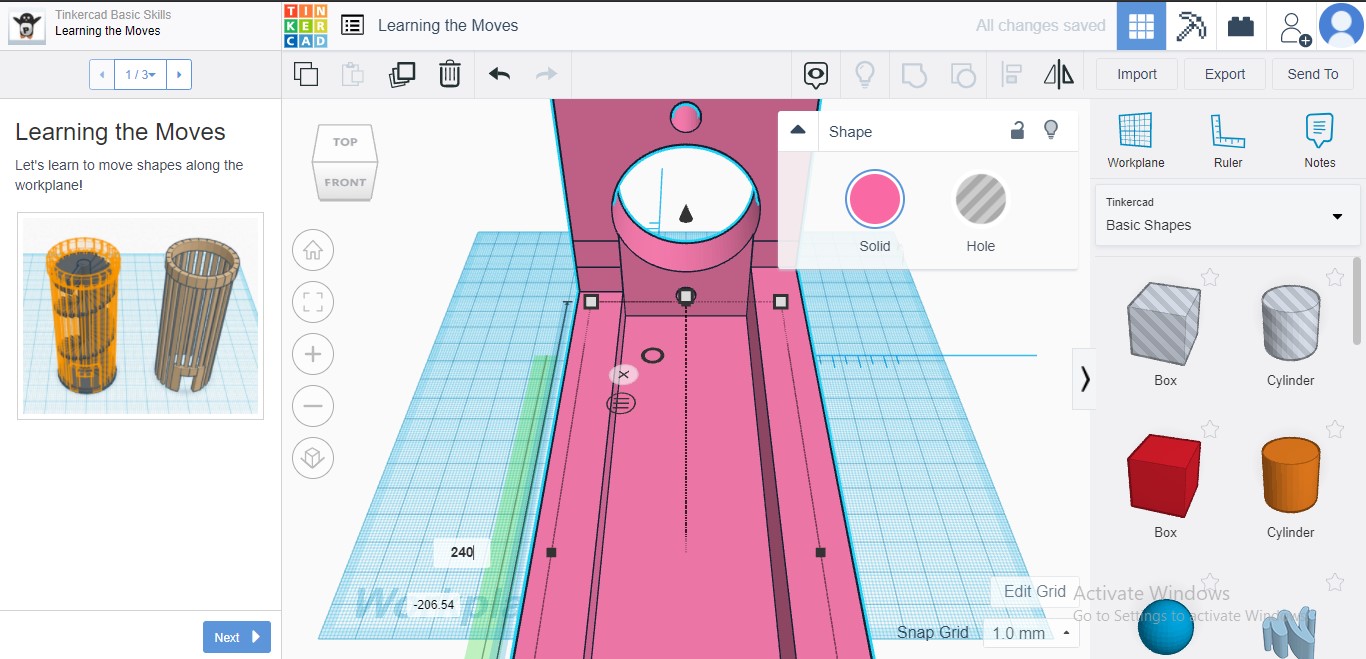
So, I changed the base length on tinkercad to 24 cm, which is a length that the 3D printer can print, after exporting the scaled down file in STL
All the parts dimensions are proportional, if I scale down one part to 10/62, I must scale down the other parts by the same factor, so I can connect them all together. I scaled down all the other parts on Fusion360.
I exported all the files to STL, which is the format that Ultimaker Cura can understand (the program connected to the 3D printer)
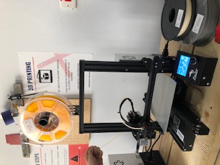
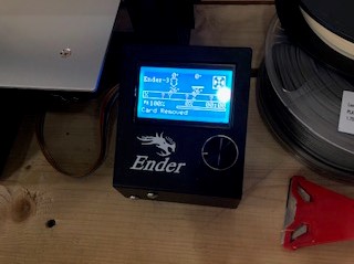
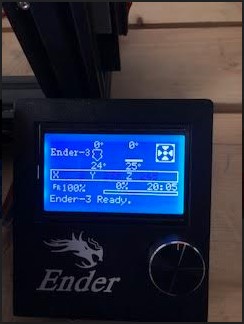
This is what the 3D printing machine (called Ender) in Fab Lab looks like
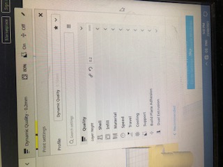
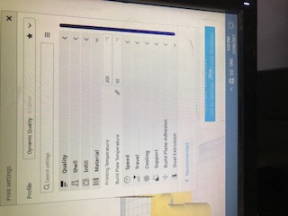
I opened the files in Ultimaker Cura and adjusted their positions to fit within the boarders
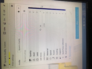
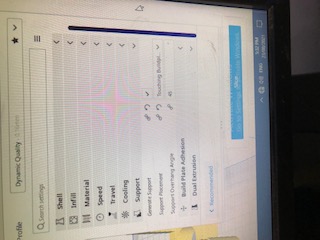
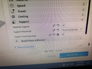
In my first attempt to print, I adjusted some parameters, to achieve high quality. I made the layer height 0.2 mm, the infill density 80% and the pattern “lines”, I chose the support to be at the bottom only at angle of 45 degrees, and the print speed 50 mm/s
The duration of the printing process was supposed to be approximately 1 day and 15 hours, which was acceptable, considering the result should be of high quality. I left it to print around 6:30 pm. I came to check on it the following morning, it turns out the filament broke, and my instructor stopped the machine. I fixed the filament issue and continued the printing process. I went to check on it again, after a couple of hours, the board moved, so the layers of the filament were not stacked on top of each other
I had to end the printing process. I used another machine, and another board. But I changed the parameters, to speed up the printing time.
These are the new parameters
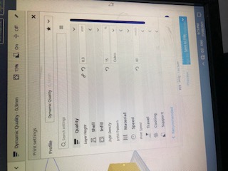
The duration decreased to approximately 21 hours, after reducing the quality.
The process went smoothly
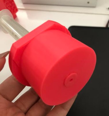
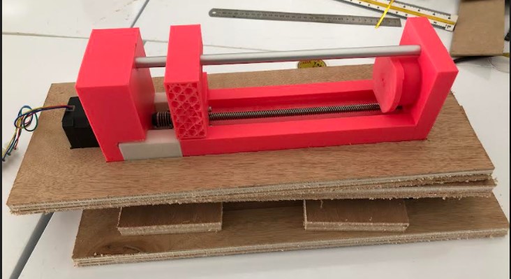
This is the end result
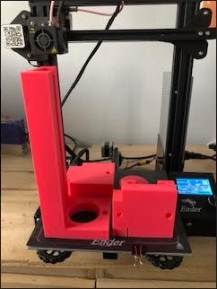
It took approximately 20 hours and 5 minutes
The metal rod fits perfectly in the base
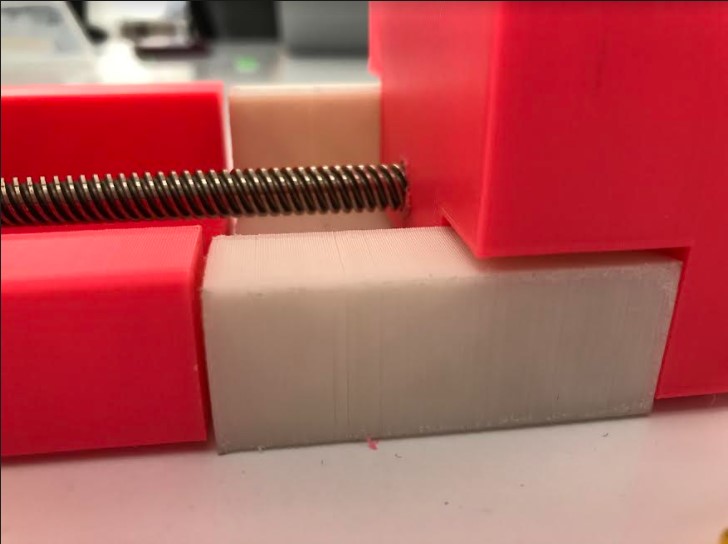
During the assembly, and while my colleagues Batool and Mahmood were working on the electronics, we realized that we need to make more pieces to connect all the parts and elements of the microsyringe pump together.
The length of the threaded rod connected to the stepper that is attached to the base piece was above 24 cm (the length of the base), so I printed a small segment of the base and we attached it to previously printed base.
In addition, another piece was needed to be fitted within the syringe holder, because the hole was too wide, the syringe did not stay in place, I simply made a hollowed cylinder on Fusion360 and printed it with the 3D printer using the same settings described above.
Electronics
Two electronic elements were tested, servo module and stepper module. More details can be found here and here.
Assembly and end result
Assembly
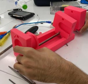
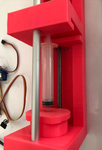
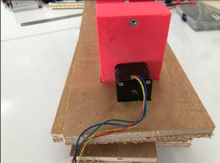
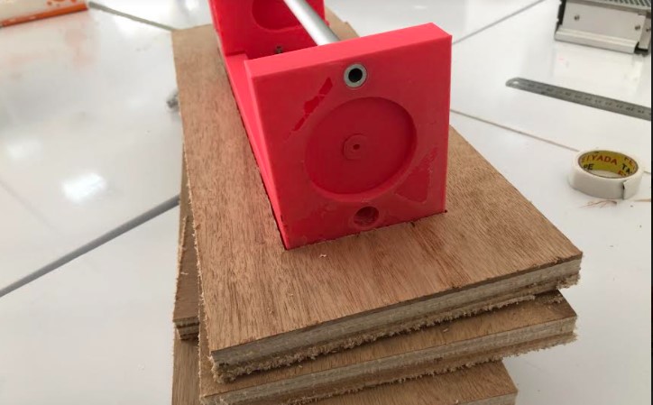
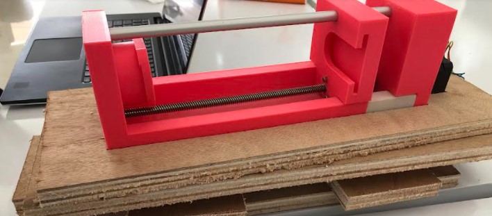
We connected the pieces together, and connected the electronic modules
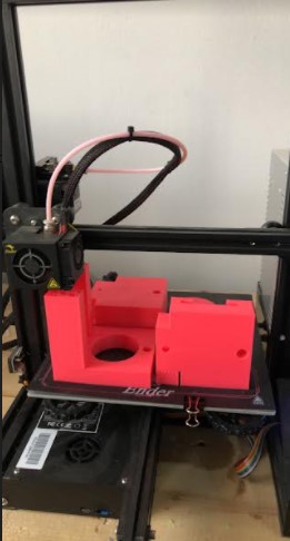
This is how it looked during the assembly process
In this link you can see a clip of the first test of the microsyringe pump.
CNC machining
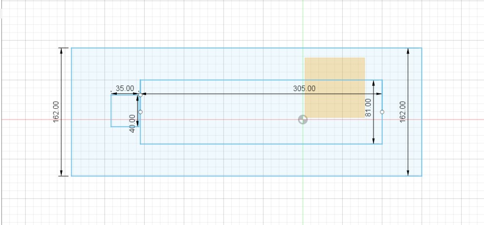
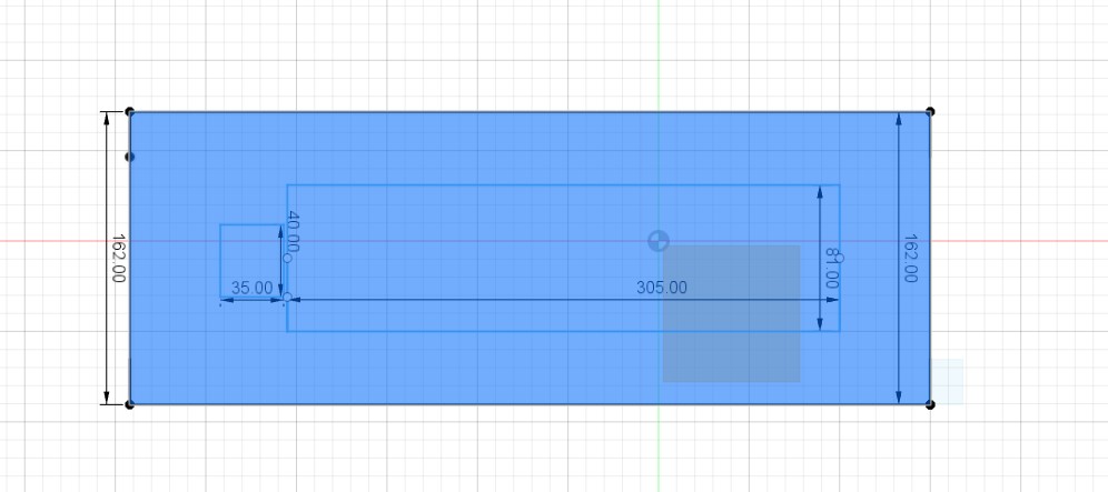
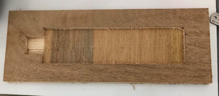
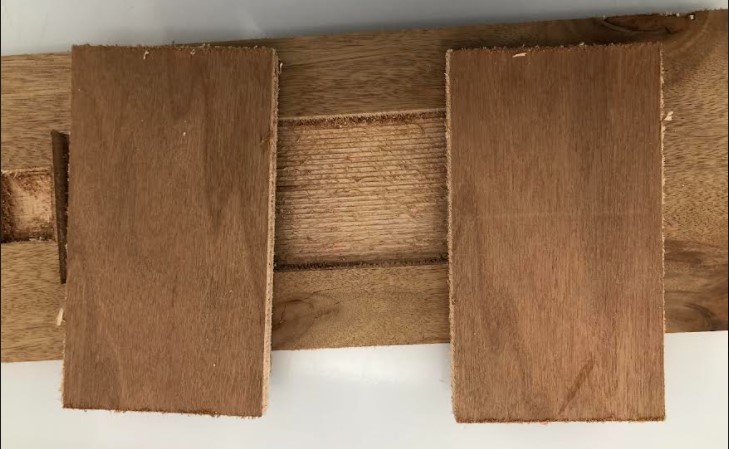
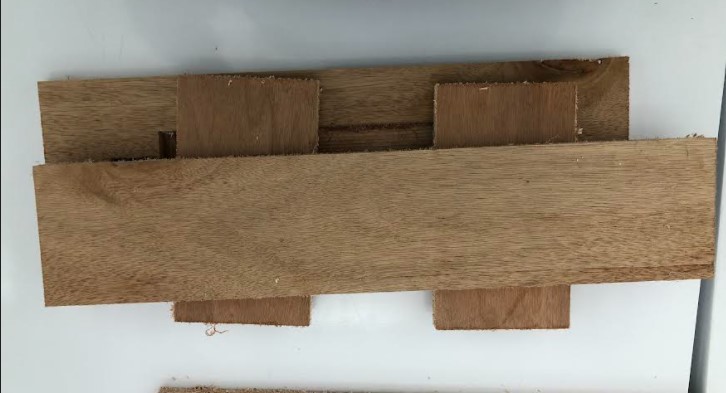
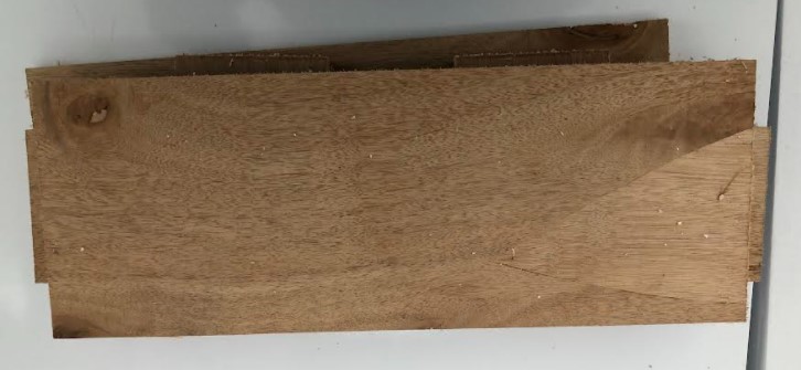
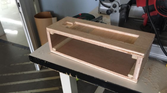
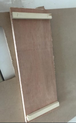
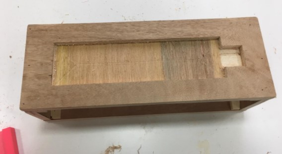
During the assembly process, we noticed that the pump setup was moving, as shown in the clip linked above, and needed something to constrain it and keep it in place, so we decided to make a wooden case and place the microsyringe pump inside it. I will show the steps of the design in the following pictures. All the parts in the design were extruded to 18 mm, because the thickness of the wood sheet was 18 mm.
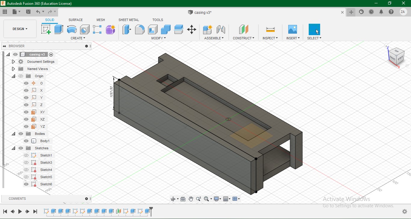
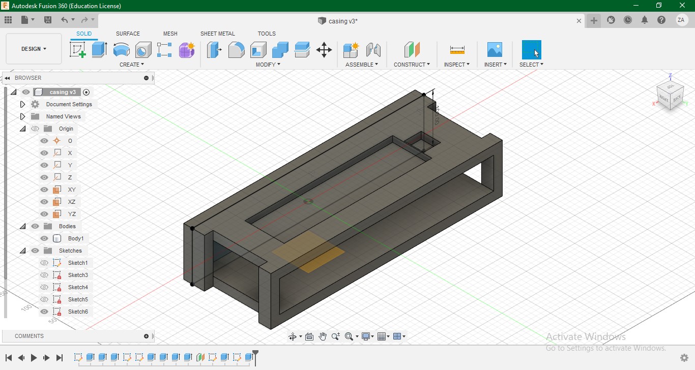
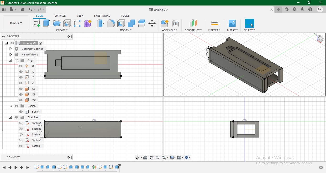
It was cut with the CNC machine, with the help of my instructor Abdulla Fadi. More details about the operation of cnc machining can be found here. However, after the cutting was complete, we assembled the pieces differently than it is shown in the design pictures, per my supervisor’s recommendation.
CO2 laser
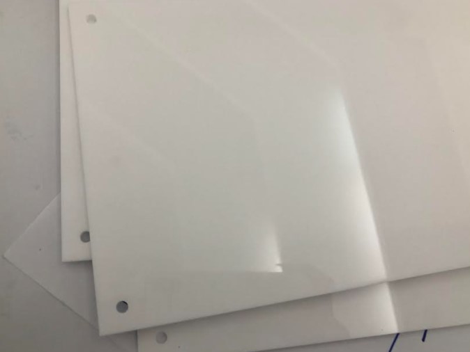
After that, we decided to cut two pieces of acrylic to cover the electronics part. We used a 3 mm thick acrylic sheet.
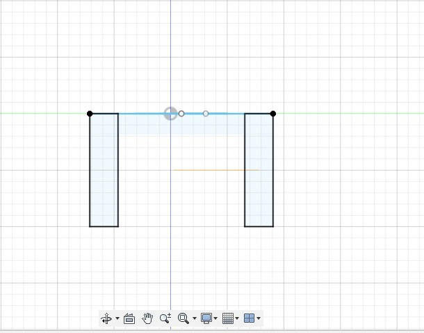
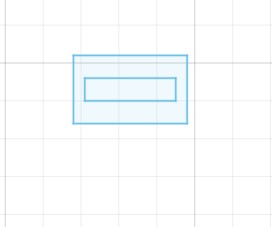
This sketch is of the back cover.
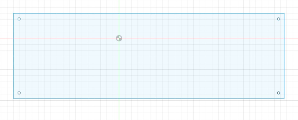
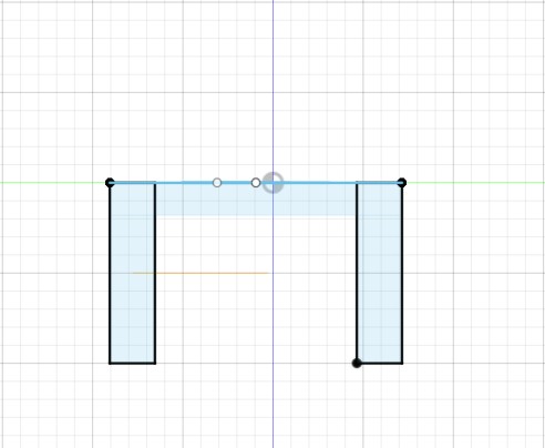
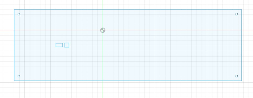
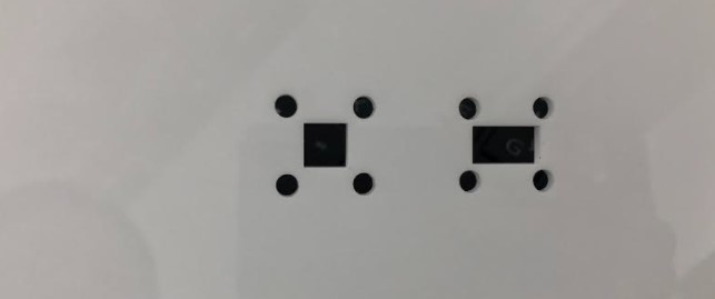
This sketch is of the front cover. It contains two rectangles that will be cut and the on/off switch and direction switch will be fitted through them.
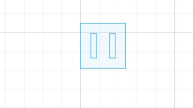
We made two pieces to put behind the rectangular holes to keep the switches in position.
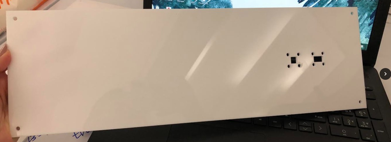
I cut the pieces on CO2 laser, at a speed of 25 mm/s and power of 40%, repeated twice.
More details about how to use the CO2 laser machine can be found here.
End result
Further details regarding assembly and the end result can be found on Batool’s and Mahmood’s websites linked in the references.