3. Lrage Format CNC
This week was mainly about designing 3D models to be cut using CNC.
Design
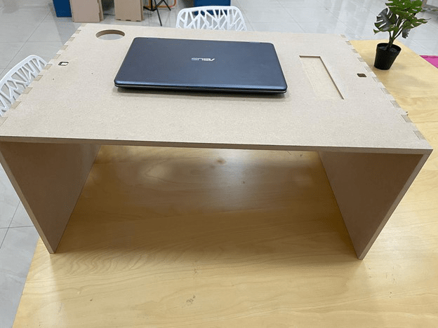
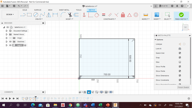
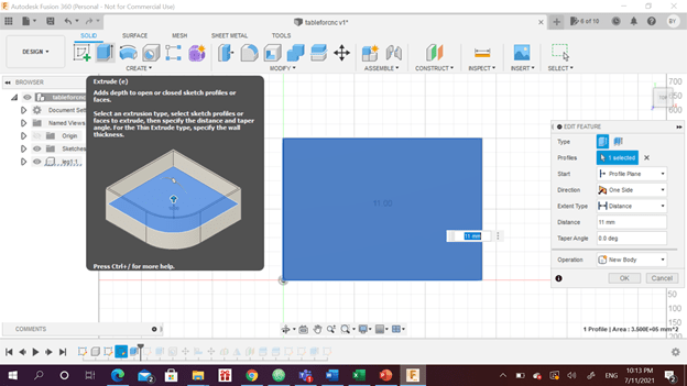
First, we carry on with fusion 360, which we used last week for the group assignment. First, I carried out the design process using create form. However, I discovered later that this type is not suitable for our assignment which requires making a joint. I started new design using sketch . the main idea was to create a studying table when setting on bed. The first step was to sketch the top of the table. I defined the measurements of the length and width. Then I extruded the sketch by the wood thickness.
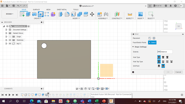
A hole was created on the corner of the top to put a coffee mug. A circle was sketched, extruded to cut the table to create the hole.
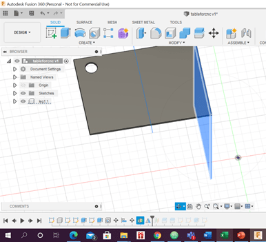
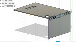
The first leg of the table was sketched, extruded and then mirrored to the other side to create the other leg.
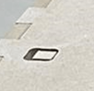
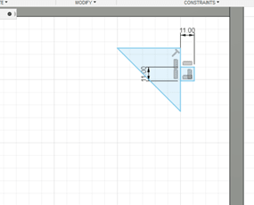
For the pens, a lower pocket was done by engraving the top of the table. I sketched a square and extruded it for 5mm only.
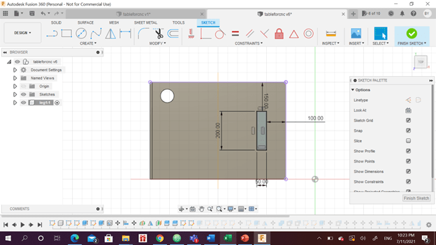
The joints were sketched on the leg by making even rectangles. These rectangles were extruded as much as the thickness.
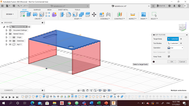
The top was moved back down and combined with the leg as cut. To create the suitable pattern in the top.
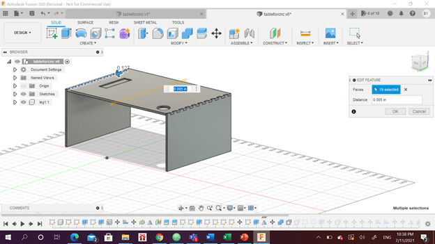
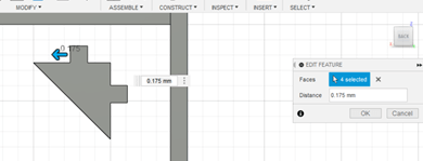
An offset to the leg joints were made to tighten the joint and to ensure that the legs would be fixed once assembled. 0.005 in were added to each face of the inner joints. This number was taken from a website that will be referenced below.
Additional supports were sketched and extruded to provide greater strength to the table. Then the same steps were executed to create the joints. Different offset value was assigned due to the difference in type of the joint. The first one was comb joint and this joint is a plug joint.
Finally the 3D design was converted to 2D design to send it to the instrument.
Cutting using CNC machine
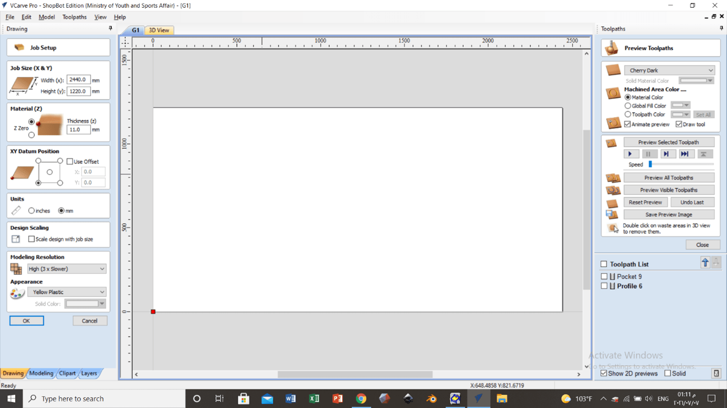
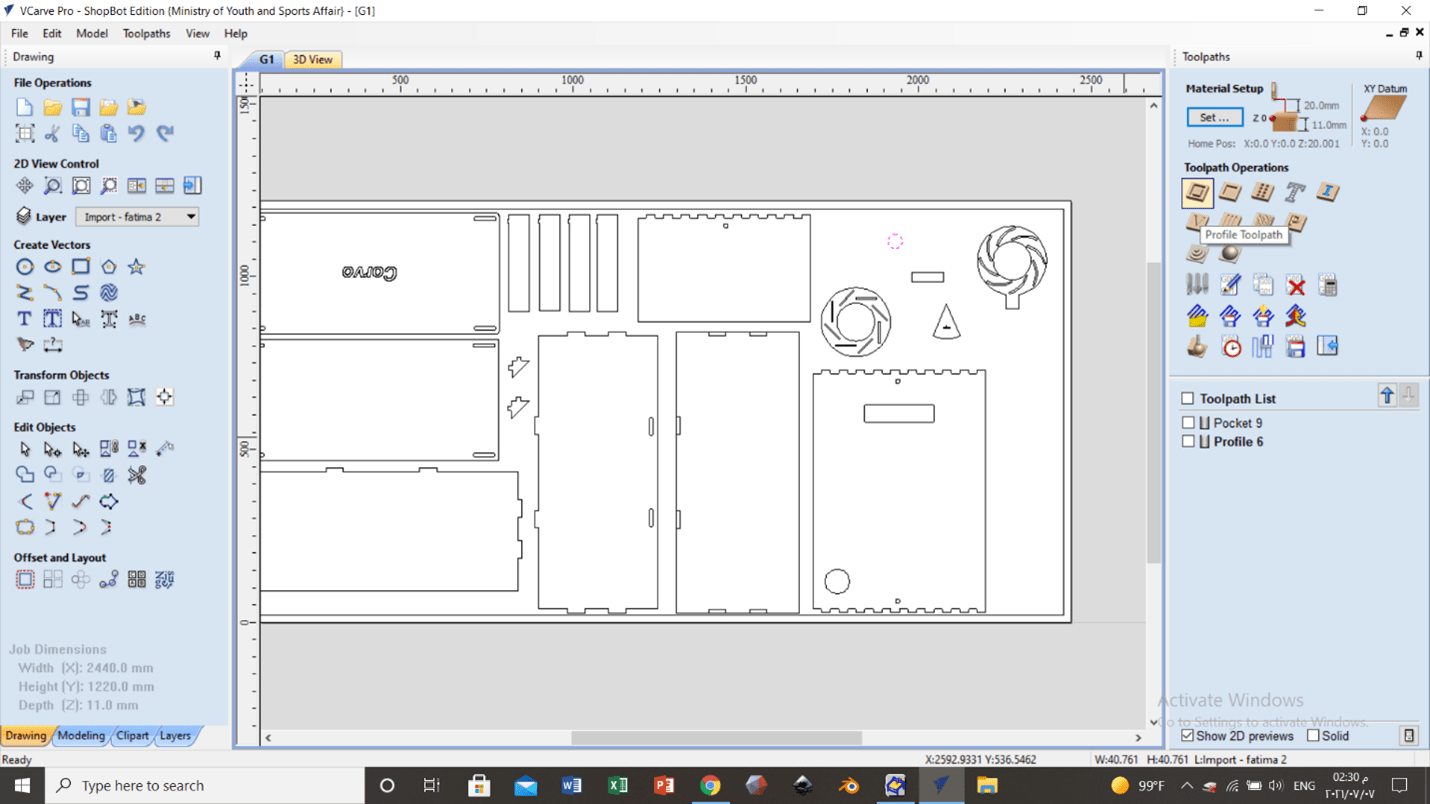
Then the manufacture procedure start, VCarve Pro was opened and the size of the available wood sheet and thickness was inserted. The zero point were located. A blank sheet appeared.
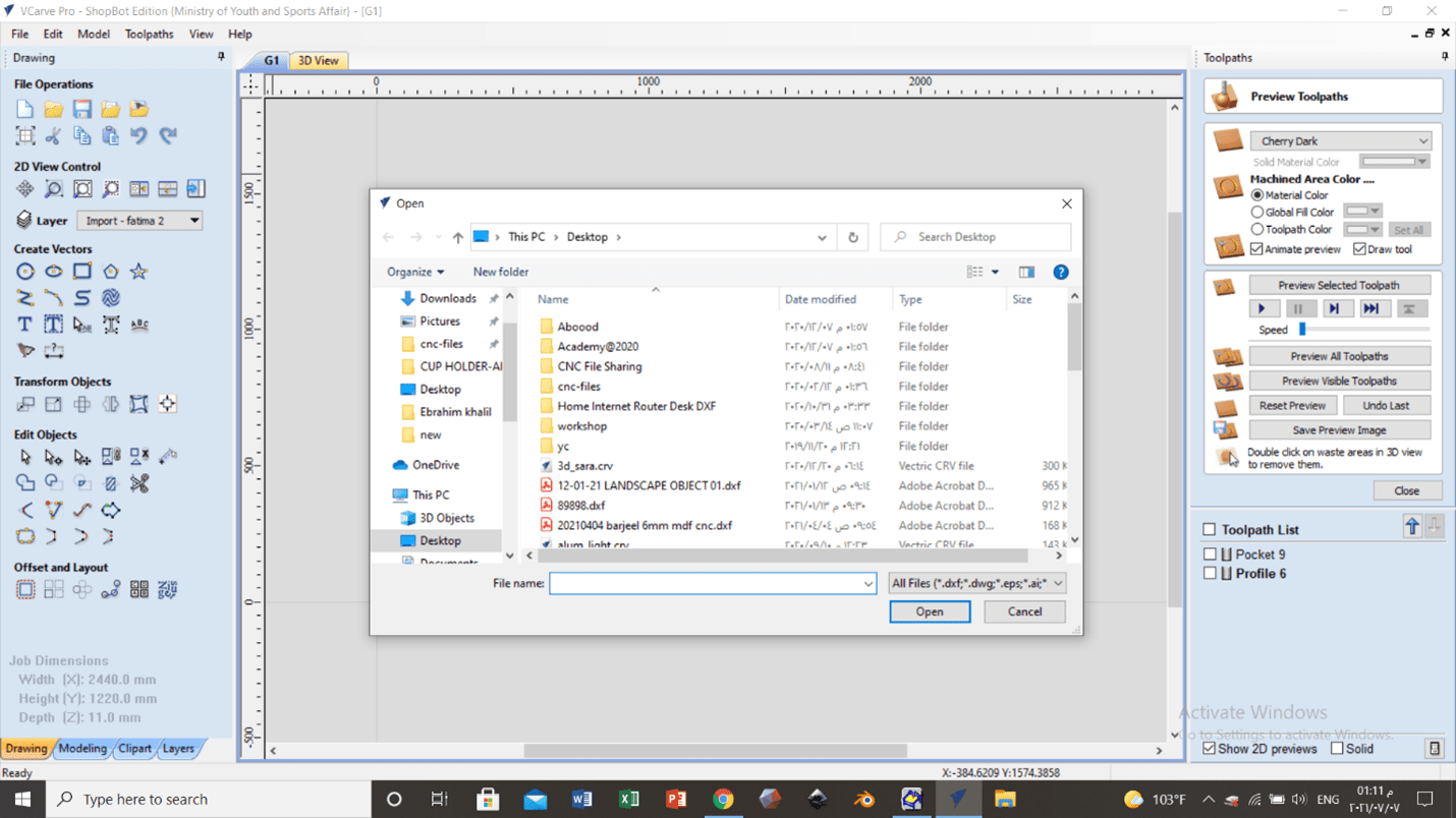
The designs were opened and the needed sketches were selected.
Then the sketches were well-arranged so that the sheet can contain sketches as much as possible. However, small space between each two sketches and a margin between the sketch and the edge of the sheet were considered to make sure that all parts are well cut.
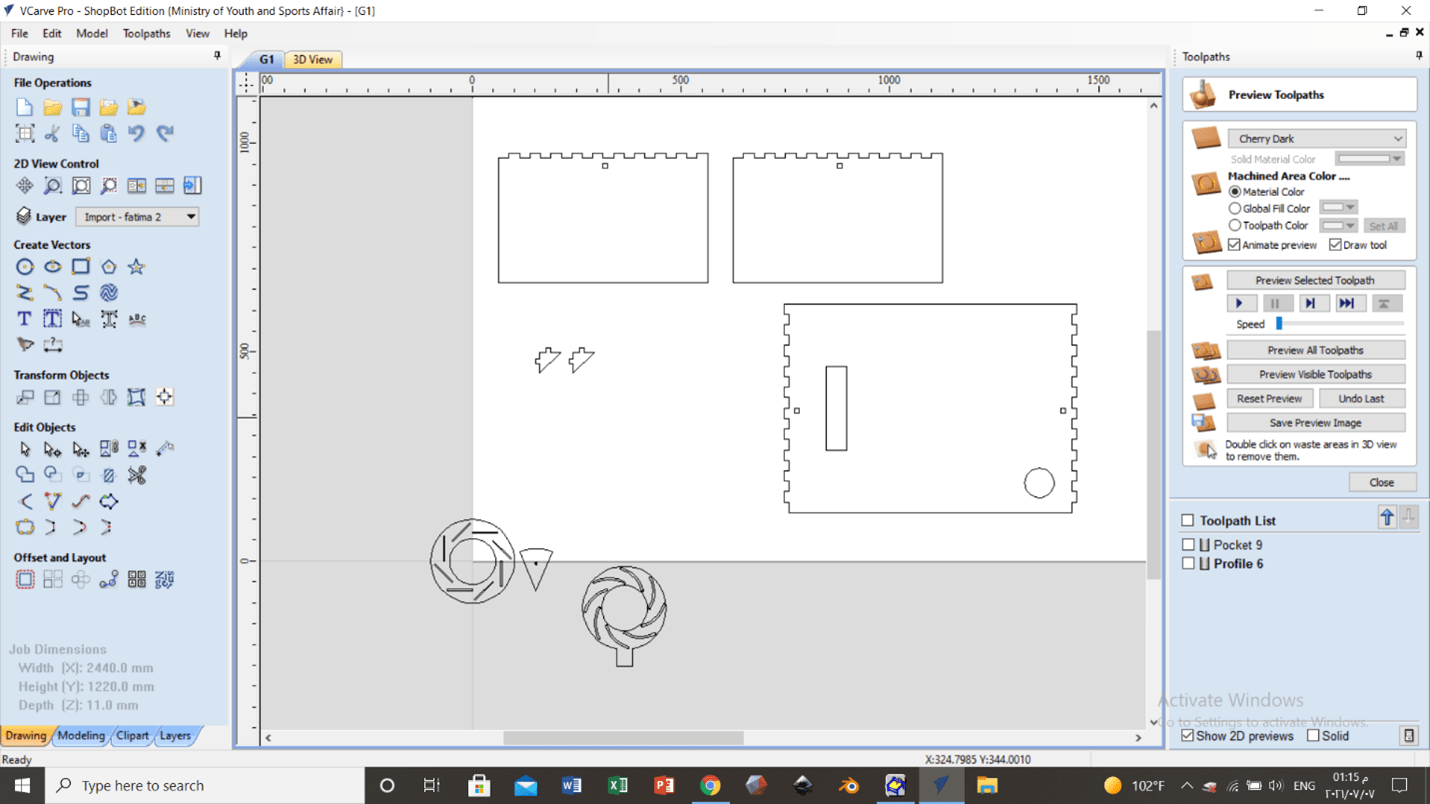
The parts can be moved by selecting the object from the right. Better selection can be done from the right rather than the left because the right can select anything it can touch. When selecting from the left you have to select the whole shape not only touch it.
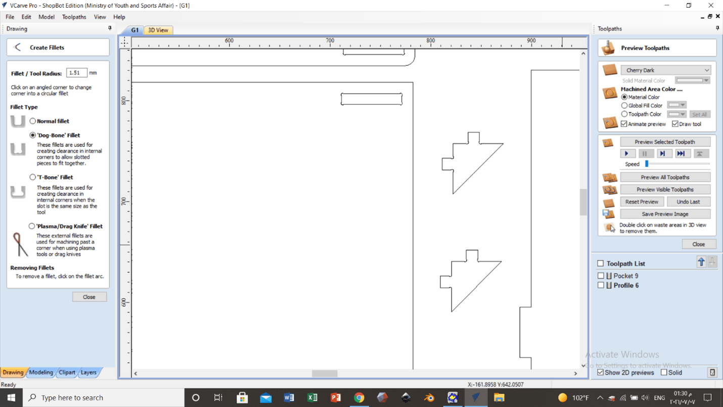
There are multiple fillet types. Dog bones were added to the edge because the machine cannot reach the inner corners of the shapes.

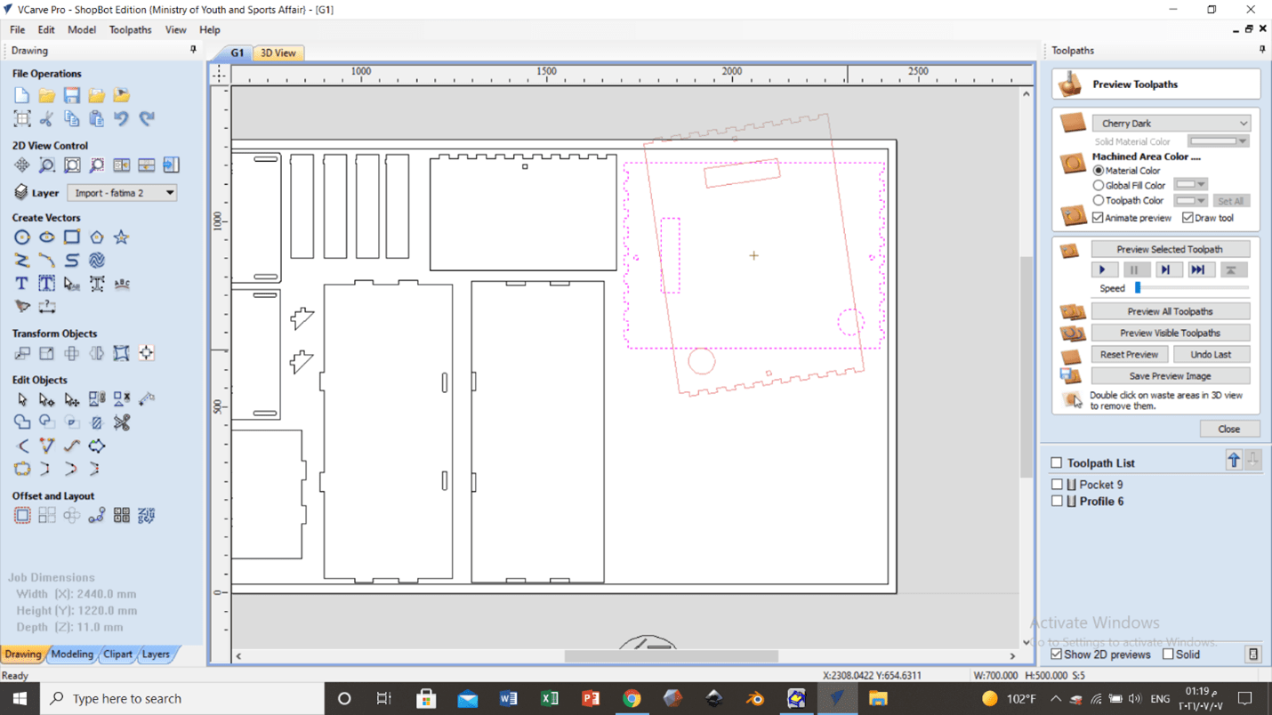
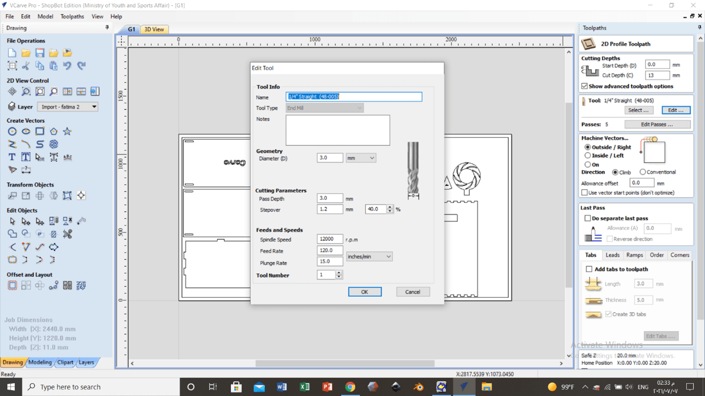
Then the tool path was adjusted from here.
The depth, start point, spindle speed and feed rate were adjusted. The tool were defined and its diameter was defined too.
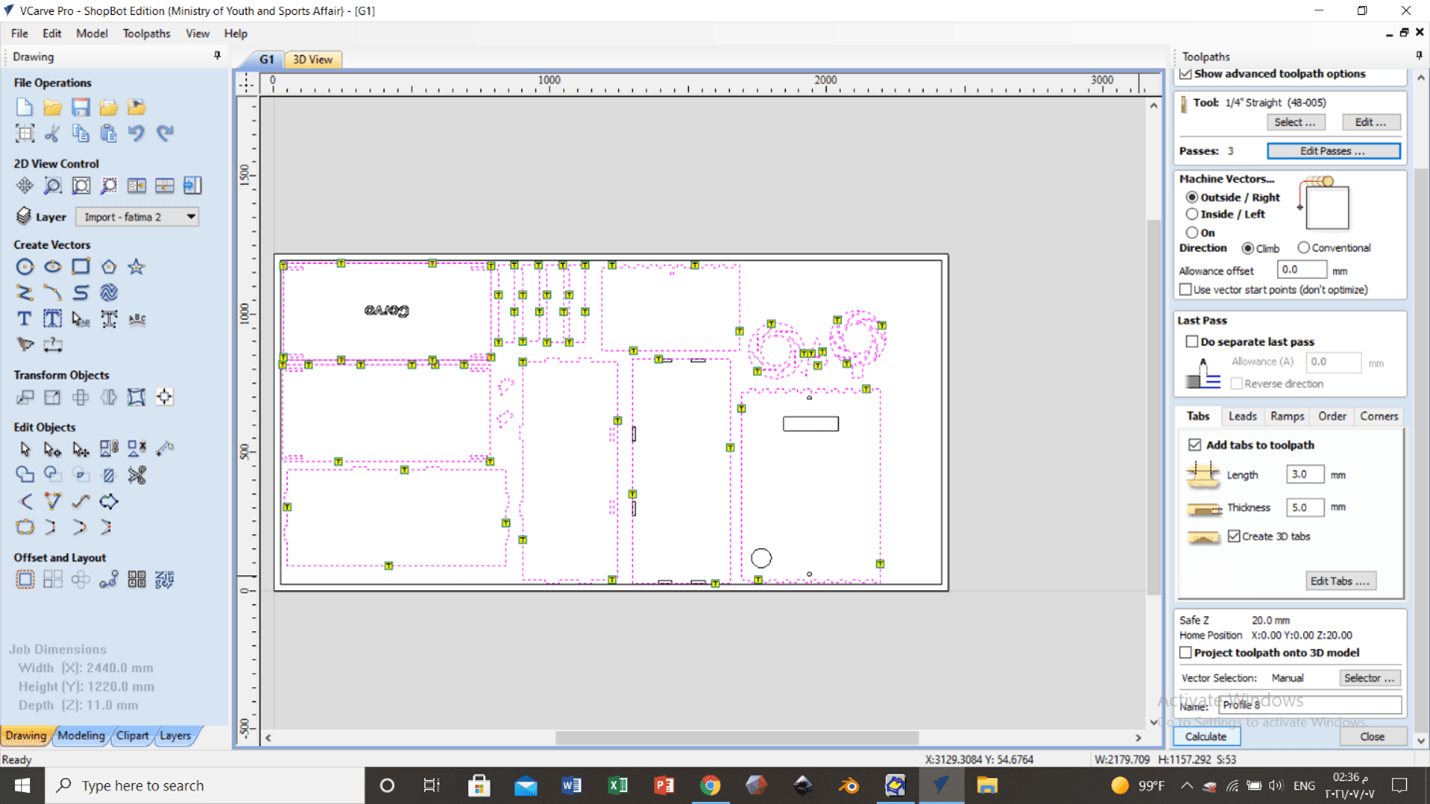
The cutting starts from the inside to the outside to prevent any movement of parts. Taps were added to ensure that the parts that will be cut will stay at their place. Taps can be removed easily later.
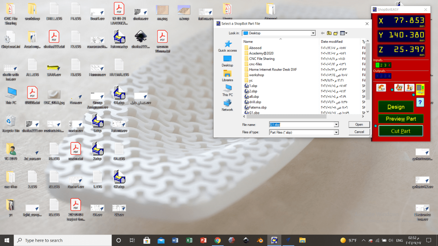
The instrument was then calibrated properly and the desired 2D file was opened. A metal part is placed beneath the head and something similar to scissors is placed on the instrument to close the electrical circuit.
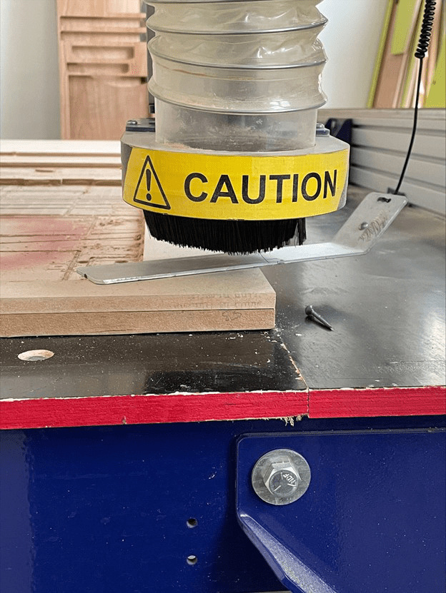
Safety
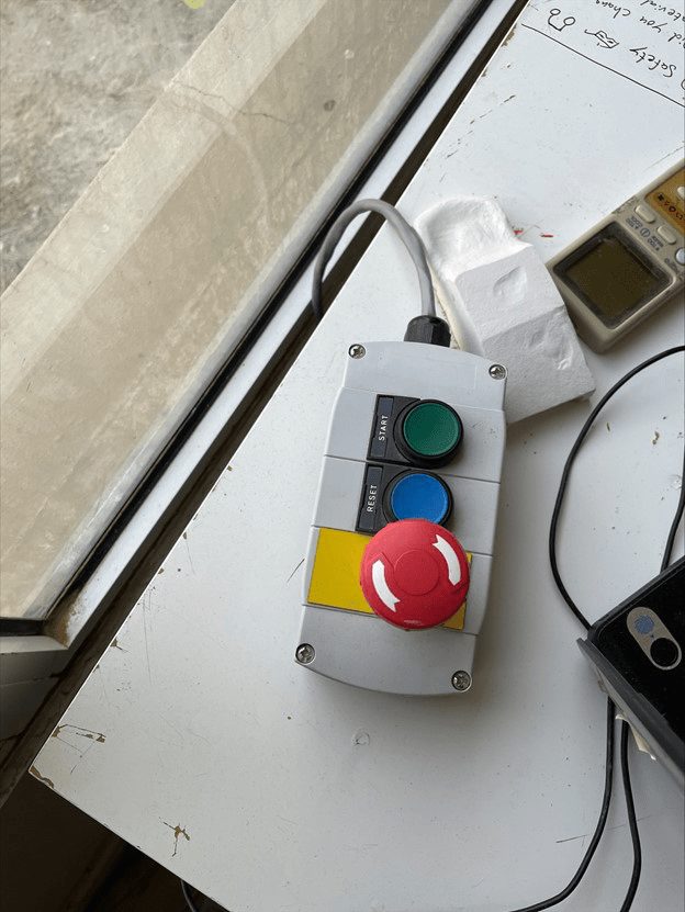
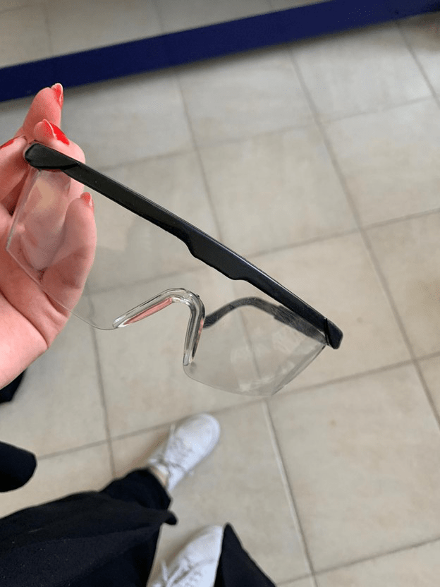
Once the cutting process starts, it can be stopped by pressing a button from the computer, a button on the table or a button on the instrument itself. This ensures safety a lot in case of accidents. Goggles must be worn all the time when dealing with the instrument.
Machine settings adjustment
The setting of the machine was optimized to the meet most suitable conditions. A detailed explanation is provided in the group assignment at the end of this page.
Assemble
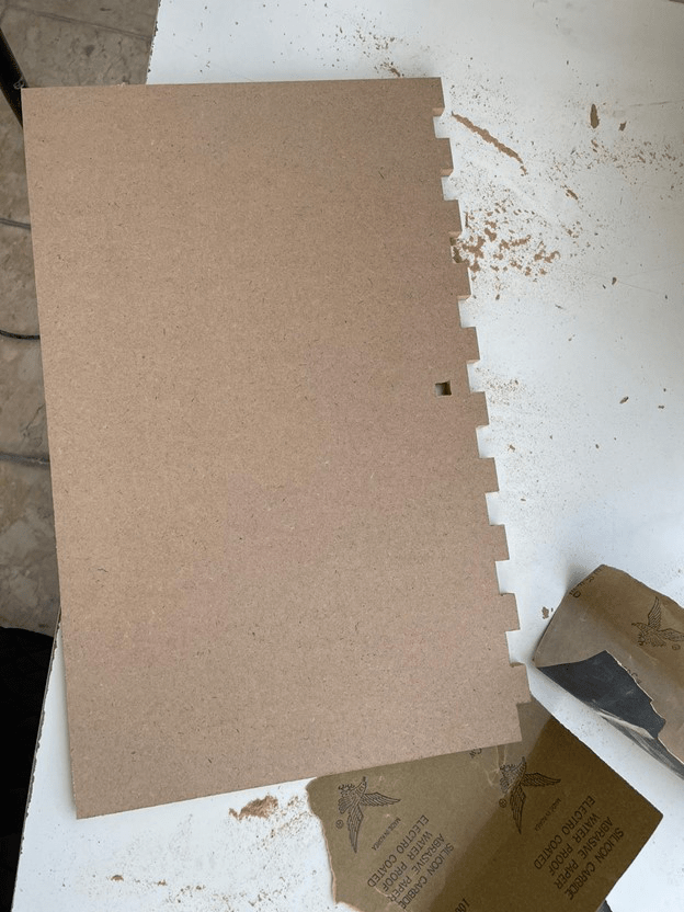
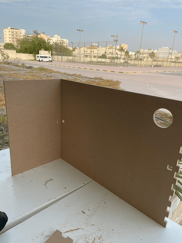
After the part being cut, we assembled them and fitted them with a hummer. One main problem was faced. It was that two of the holes intended to climb the support was too big because it was cut from the outside rather than from the inside. This problem can be avoided by making sure the cut will be from the inside.
This option can be selected from the toolpath in the machine vectors where it has to be inside/left.
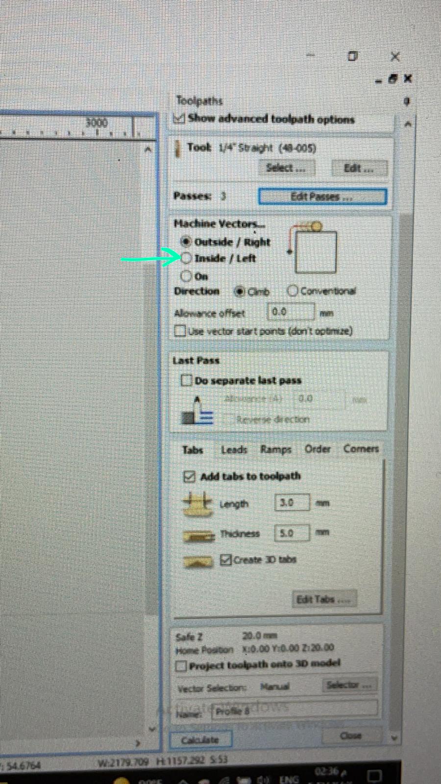
A solution for the current problem is to use a prober filling to close the gap.