4. Embedded programming
What is the Arduino ?
Arduino is an open-source electronics platform based on easy-to-use hardware and software. Arduino boards are able to read inputs - light on a sensor, a finger on a button, or a Twitter message - and turn it into an output - activating a motor, turning on an LED, publishing something online. You can tell your board what to do by sending a set of instructions to the microcontroller on the board. To do so you use the Arduino programming language (based on Wiring), and the Arduino Software (IDE), based on Processing. The definition of the Arduino
The Arduino version
First , I got my first Arduino that I will program it called Arduino NANO 33 sense
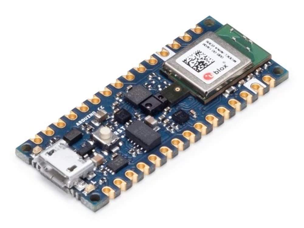 Its features
The explanation of the Arduino components :
Analog and digital signals :
Before I understand the pins and the voltages in the Arduino I had to know the basics of signals . The signals are divided into two type Analog signals and Digital signals
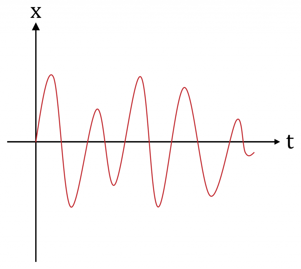
Analog signals :
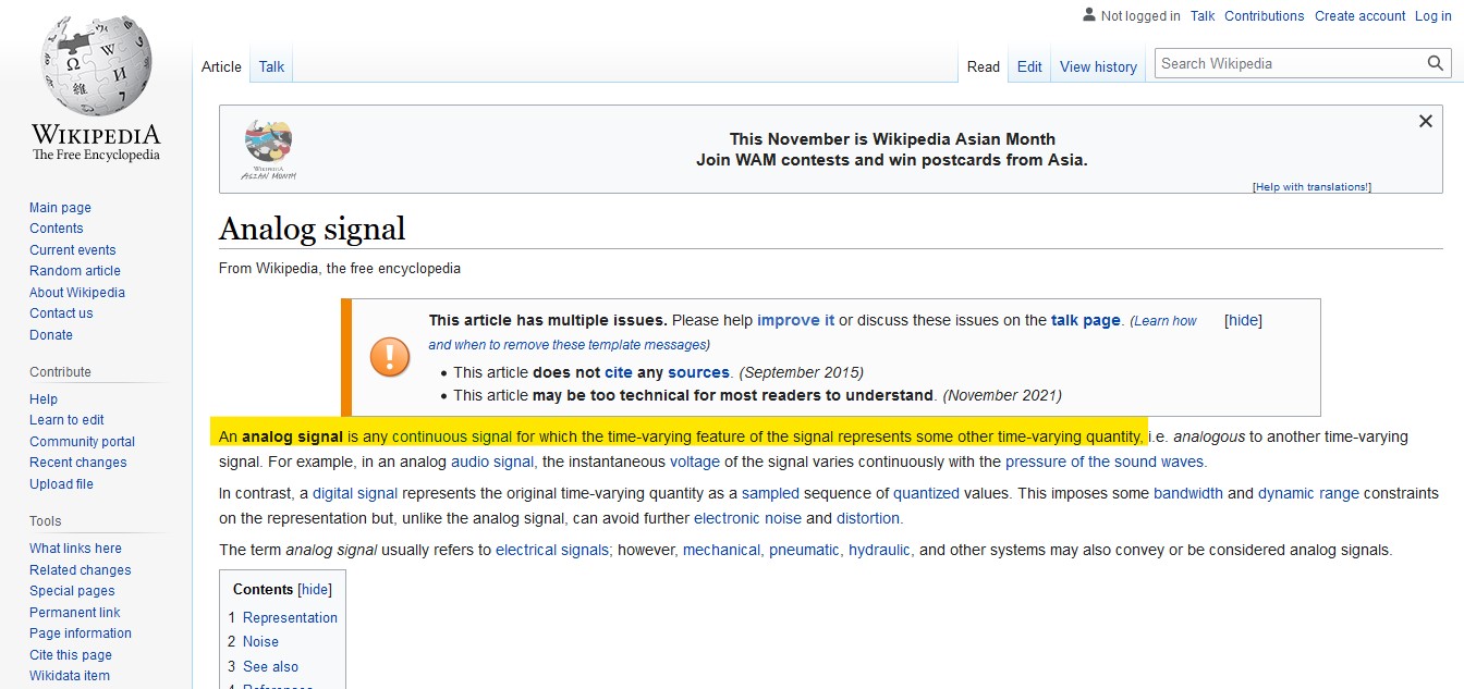 We can define the Analog signals as functions like Sin or Cos .
Examples of Analog signals : Human voice and Thermometer .
We can define the Analog signals as functions like Sin or Cos .
Examples of Analog signals : Human voice and Thermometer .
digital signals :
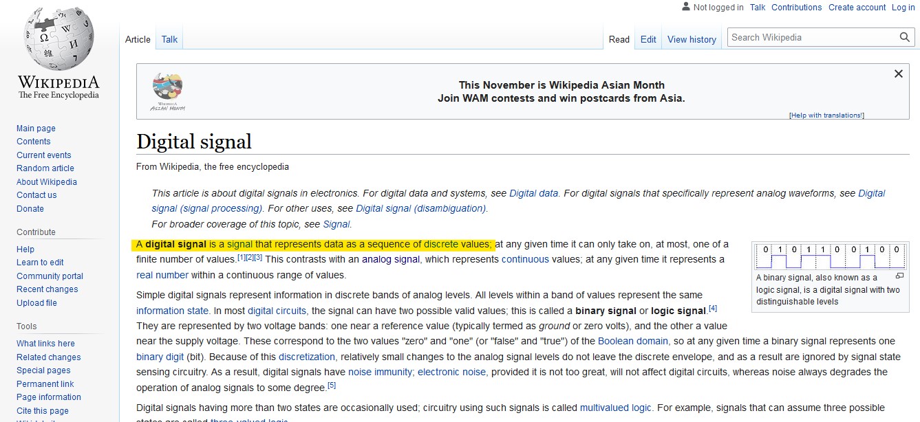 We can Imagen the digital signals as square waves which have two values , or we can imagen them as binary numbers (0,1) , also we can imagen them as on and off process .

The difference between Analog and digital signals :

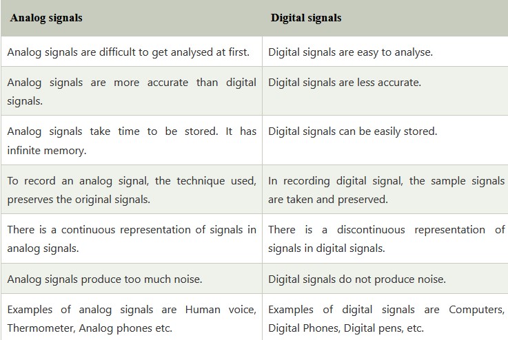
Difference between Analog and Digital Signals Difference between Analog and Digital Signals
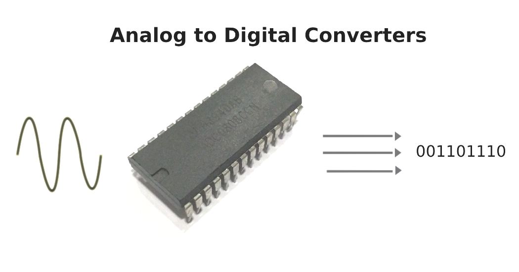
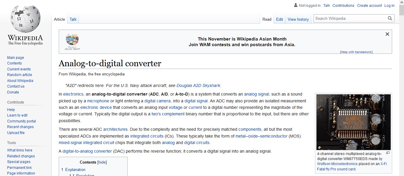
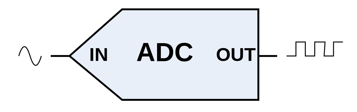
How the Arduino reads the analog signals ?
Simply , the Arduino has a component can convert the analog signals to digital signals called ADC (Analog-to-digital converter) . this component can divide the analog signals into pieces and then convert them to binary code .
Pins :
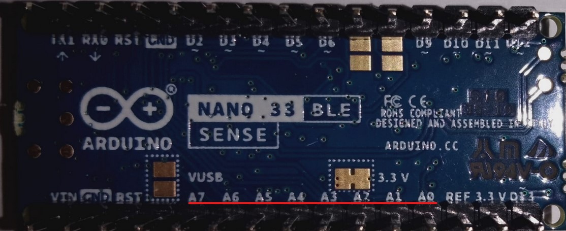
Analog pins :
The Analog pins are the pins which we can connect any device that will drive an analog signal to the Arduino on them , like sensor , thermometer or motor .
Digital pins :
The Digital pins are the pins which we can connect any device has on and off process , like buttons , lights .
If the pins have (~) so they can be used as analog pins also , because they well generate an analog signal with a method called PWM (Pulse-width modulation)

If the pin does not have (~) we can just use it for digital devices :

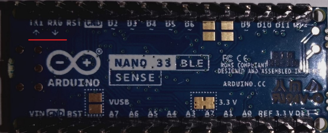
RX - TX :
These pins can be used as a USB when we connect other device with our Arduino like other Arduino or Bluetooth module .
Voltages :
There are two pins or voltages :
1_VIN: which we can connect any device that will drive voltages between 4.5V to 21V to the Arduino .
2_3.3V: this pin generate 3.3V to the devices that will be connected to the Arduino

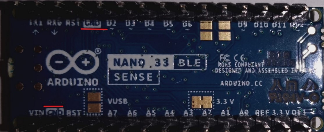
we can connect the negative terminals of the devices on the ground pins :
Useful videos to understand the Arduino :
Arduino Tutorial: Overview of Arduino Pins
Arduino Hardware - Computerphile
The programing environments :
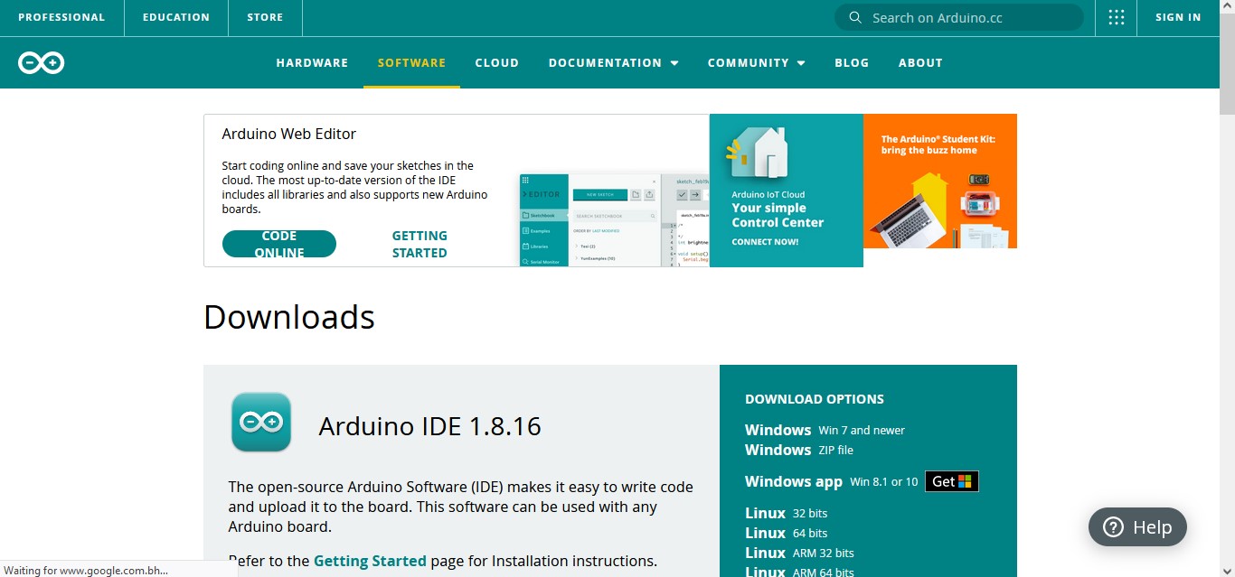
Arduino IDE
In the first time I worked with a programing environment called Arduino IDE it is the main programing environment for the Arduino
connecting the Arduino to the program
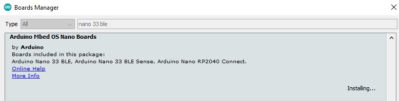
First of all I installed the desktop of the version of my Arduino in the program to allow myself to program the board :
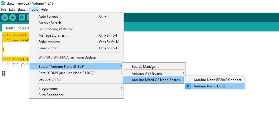
 Then I chose it from Tools > Board :
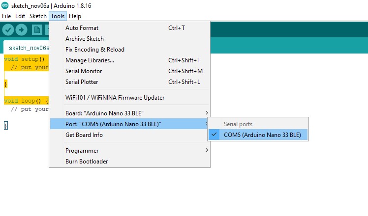
 After I connected the board to the computer I chose it from Tool > Port :
The first program (Blinking)
In this time I just tested how can I make the light blinking with an existing code
I found the code from File > Examples > Basics > Blink
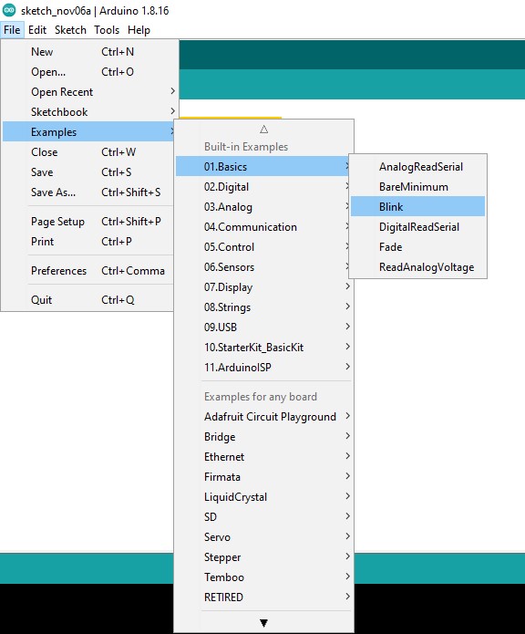
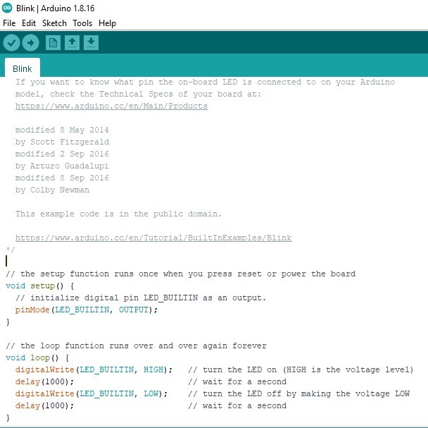
This code will going to make the light on and off each second
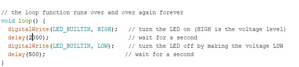
I tried to change the delay to 2 seconds :
Then tried to use Morse code to let the light blinking the word Fablab

The challenge was pre code your microcontroller to send a Morse code 1 word message and challenge a friend, family member, your colleagues or your instructor to figure it out. dot = 0.5 second light on. dash=1 second light on. gap between dots and dashes=0.5 second light off. gap between letters=2 second light off
`
 void loop()

 digitalWrite(LED_BUILTIN, LOW );   // turn the LED on (HIGH is the voltage level)
  delay(500);
  digitalWrite(LED_BUILTIN, HIGH);   // turn the LED on (HIGH is the voltage level)
    delay(500);
    digitalWrite(LED_BUILTIN, LOW );   // turn the LED on (HIGH is the voltage level)
    delay(500);
    digitalWrite(LED_BUILTIN, HIGH);   // turn the LED on (HIGH is the voltage level)
    delay(1000);
    digitalWrite(LED_BUILTIN, LOW );   // turn the LED on (HIGH is the voltage level)
    delay(500);
    digitalWrite(LED_BUILTIN, HIGH);   // turn the LED on (HIGH is the voltage level
    delay(500);
    digitalWrite(LED_BUILTIN, LOW );   // turn the LED on (HIGH is the voltage level)
    delay(2000);
    digitalWrite(LED_BUILTIN, HIGH);   // turn the LED on (HIGH is the voltage level)
    delay(500);
    digitalWrite(LED_BUILTIN, LOW );   // turn the LED on (HIGH is the voltage level)
    delay(500);
    digitalWrite(LED_BUILTIN, HIGH);   // turn the LED on (HIGH is the voltage level)
    delay(1000);
    digitalWrite(LED_BUILTIN, LOW );   // turn the LED on (HIGH is the voltage level)
    delay(2000);
    digitalWrite(LED_BUILTIN, HIGH);   // turn the LED on (HIGH is the voltage level)
    delay(1000);
    digitalWrite(LED_BUILTIN, LOW );   // turn the LED on (HIGH is the voltage level)
    delay(500);
    digitalWrite(LED_BUILTIN, HIGH);   // turn the LED on (HIGH is the voltage level
    delay(500);
    digitalWrite(LED_BUILTIN, LOW );   // turn the LED on (HIGH is the voltage level)
    delay(500);
    digitalWrite(LED_BUILTIN, HIGH);   // turn the LED on (HIGH is the voltage level)
    delay(500);
    digitalWrite(LED_BUILTIN, LOW );   // turn the LED on (HIGH is the voltage level)
    delay(500);
    digitalWrite(LED_BUILTIN, HIGH);   // turn the LED on (HIGH is the voltage level)
    delay(500);
    digitalWrite(LED_BUILTIN, LOW );   // turn the LED on (HIGH is the voltage level)
    delay(500);
    digitalWrite(LED_BUILTIN, LOW );   // turn the LED on (HIGH is the voltage level)
    delay(2000);
    digitalWrite(LED_BUILTIN, HIGH);   // turn the LED on (HIGH is the voltage level)
    delay(500);
    digitalWrite(LED_BUILTIN, LOW );   // turn the LED on (HIGH is the voltage level)
    delay(500);
    digitalWrite(LED_BUILTIN, HIGH);   // turn the LED on (HIGH is the voltage level)
    delay(1000);
    digitalWrite(LED_BUILTIN, LOW );   // turn the LED on (HIGH is the voltage level)
    delay(500);
    digitalWrite(LED_BUILTIN, HIGH);   // turn the LED on (HIGH is the voltage level)
    delay(500);
    digitalWrite(LED_BUILTIN, LOW );   // turn the LED on (HIGH is the voltage level)
    delay(500);
    digitalWrite(LED_BUILTIN, HIGH);   // turn the LED on (HIGH is the voltage level)
    delay(500);
    digitalWrite(LED_BUILTIN, LOW );   // turn the LED on (HIGH is the voltage level
    delay(2000);
    digitalWrite(LED_BUILTIN, HIGH);   // turn the LED on (HIGH is the voltage level)
    delay(500);
    digitalWrite(LED_BUILTIN, LOW );   // turn the LED on (HIGH is the voltage level)
    delay(500);
    digitalWrite(LED_BUILTIN, HIGH);   // turn the LED on (HIGH is the voltage level)
    delay(1000);
    digitalWrite(LED_BUILTIN, LOW );   // turn the LED on (HIGH is the voltage level)
    delay(2000);
    digitalWrite(LED_BUILTIN, HIGH);   // turn the LED on (HIGH is the voltage level)
    delay(1000);
    digitalWrite(LED_BUILTIN, LOW );   // turn the LED on (HIGH is the voltage level)
    delay(500);
    digitalWrite(LED_BUILTIN, HIGH);   // turn the LED on (HIGH is the voltage level)
    delay(500);
    digitalWrite(LED_BUILTIN, LOW );   // turn the LED on (HIGH is the voltage level)
    delay(500);
    digitalWrite(LED_BUILTIN, HIGH);   // turn the LED on (HIGH is the voltage level)
    delay(500);
    digitalWrite(LED_BUILTIN, LOW );   // turn the LED on (HIGH is the voltage level)
    delay(500);
    digitalWrite(LED_BUILTIN, HIGH);   // turn the LED on (HIGH is the voltage level)
    delay(500);
    digitalWrite(LED_BUILTIN, LOW );   // turn the LED on (HIGH is the voltage level)
    delay(500);
    digitalWrite(LED_BUILTIN, LOW );   // turn the LED on (HIGH is the voltage level)
    delay(5000);
`
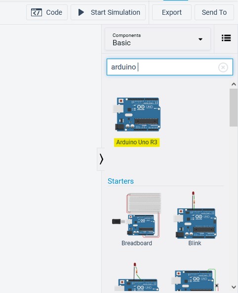
Tinkercad

First , I had to press Circuit

Then press create new circuit

I searched about the Arduino :
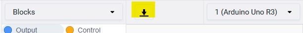
After that I change the time of the blocks to let the light blinks quickly :
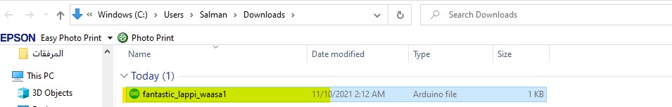
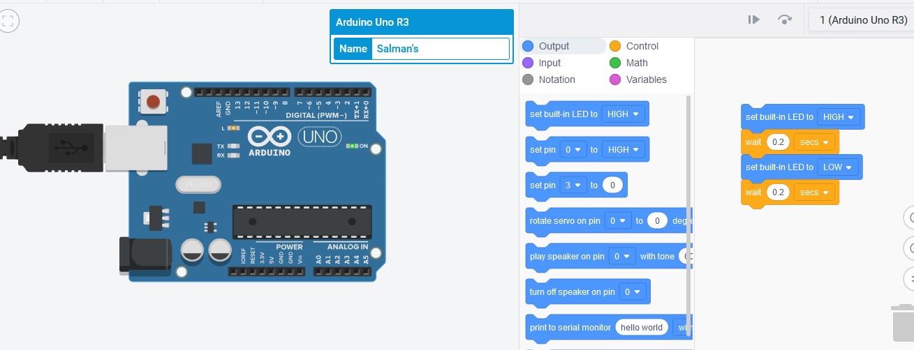 I downloaded the code :
 I clicked on it :
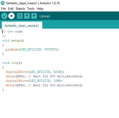
 The code is opened in Arduino IDE , now just I had to upload it to the board
Videos
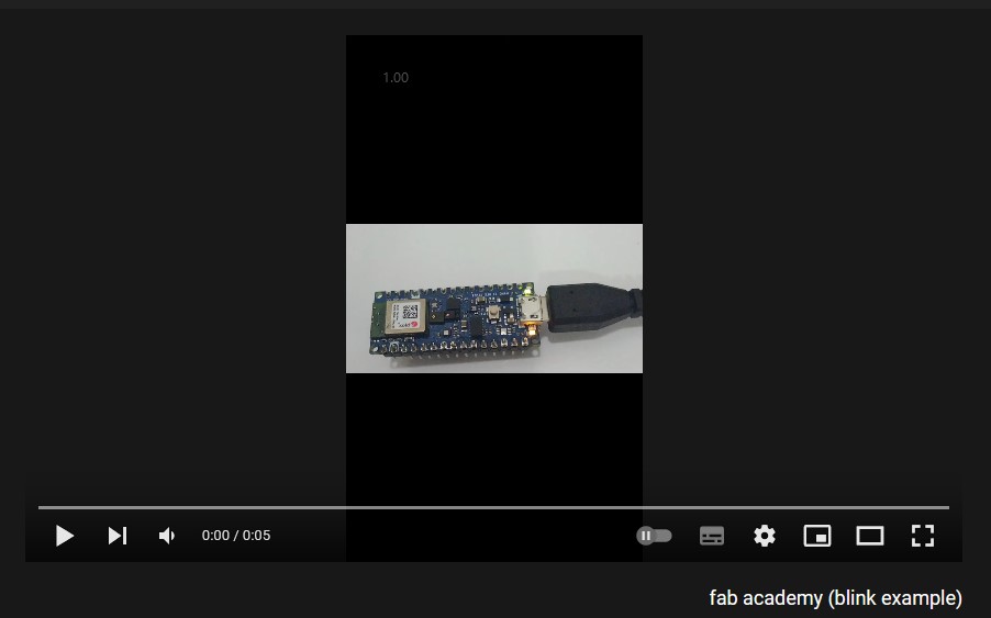
How the Arduino blinks
The challenge
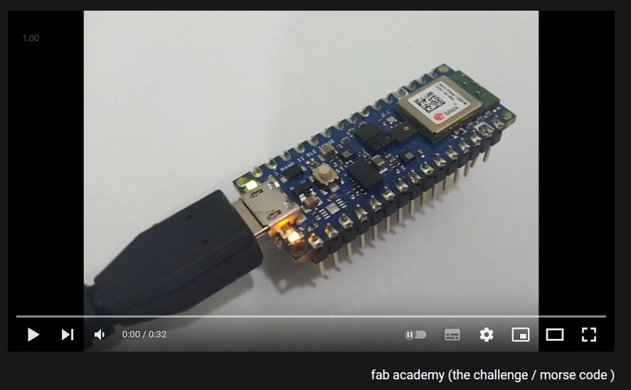 fab academy (the challenge / morse code )
using Tinkercard
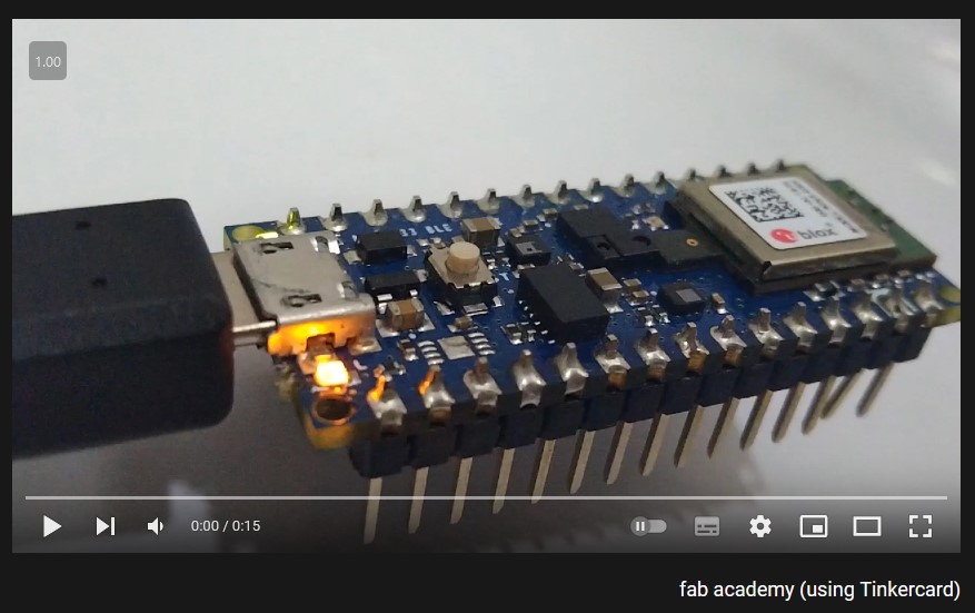 fab academy (using Tinkercard)