Final Project ( Smart Box )
The Smart Watch ( The first project ) :
At the beginning I was willing to make a smart watch , My plane to make a watch that has the ability to tell me the time and the temperature and I wanted to build a study mode in it .
I decided to make use these electronics elements as hardware for the watch :

I saw them in a YouTube video
For the software I decided to connect the Arduino with the phone using BLE .
but then the things seemed more harder than I expected , specially for the code of the screen , so I decided to reduce the functions of the watch and to use RGB and vibration motor instead of the screen . and I planed for it :

The Challenges :
I had three main challenges while making the smart watch :
The First Challenge
The first challenge was the Making the application and the coding part : At the beginning I spent my whole time on making an application that can receive and send information between the Arduino and the phone . I was able to send information to the arduino but I was not able to reseve any of them .
The Second Challenge
The second challenge was the Electronics : I had to figur out a way to connect a all of the electronics elements that i will use .
1 - The Arduino
2 - The Batary and its regulater
3 - The Viabration motore
4 - The RGB
Switching Point
After I could not make any progress in the smart watch and I saw the reducing of the functions did not work , I decided to change whole my project on something more simple than it, and I could do it in just the remaining two days , and I decided instead of doing a smart watch I will do a smart box.
The Smart Box :
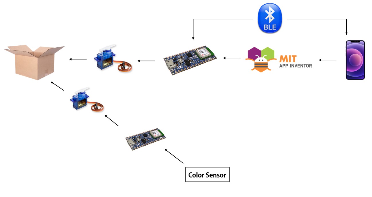
The smart box is a box that has the ability to open and close with a new and simple way , the door of this box will be connected to a servo motor, also it will opened and closed using the color sensor of the Arduino and an application made from MIT app inventor .
The design :
I had to plan for the Box :
The Challenges
In this project I had two main challenges :
The First Challenge
The first challenge was the time , I had to complete the design in two days . so I decided that in the first day I will work on the softwar which is the arduino programe , and in the next day I will work on the hardware which is the box and the mechanism on the motore .
The Second Challenge
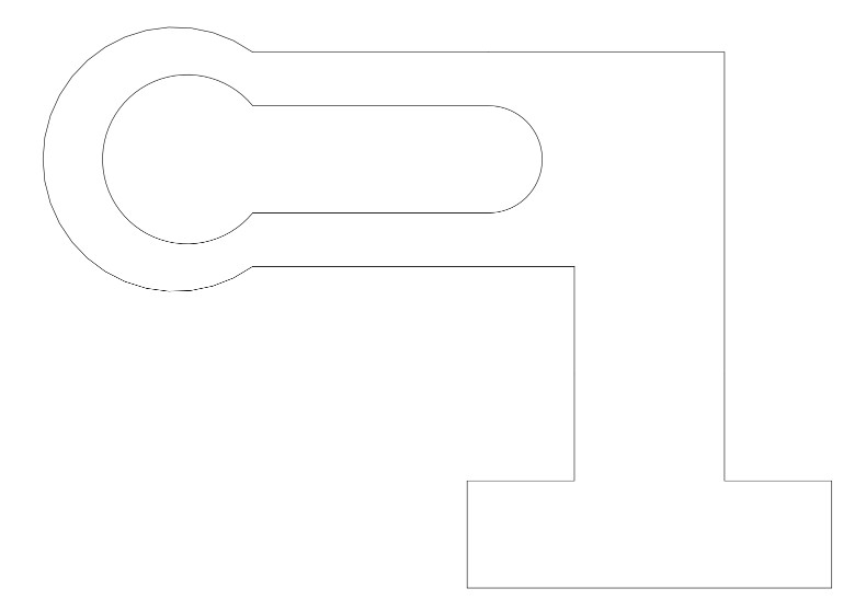
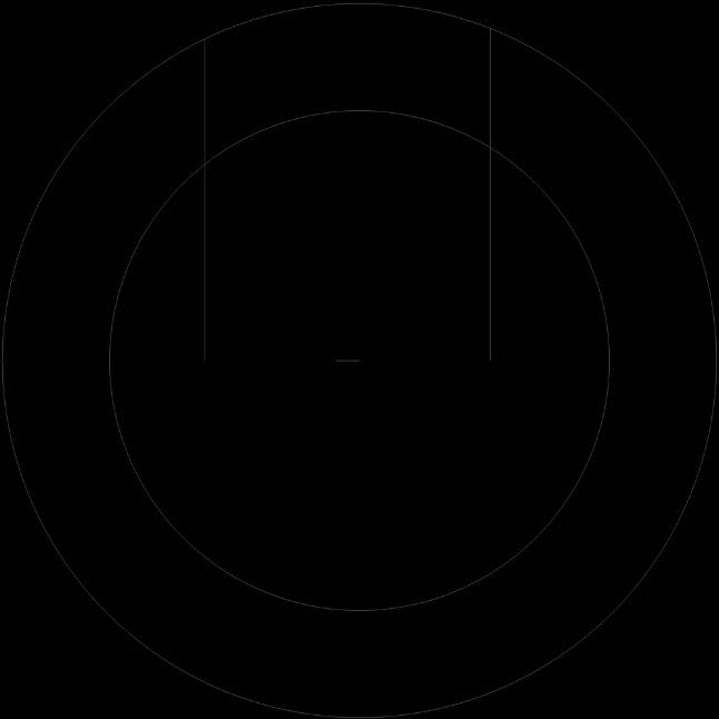
The second challenge was the design and the mechanism of the door . I thought about this shape :
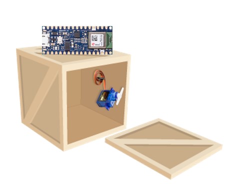
because it will allow me to set reach the Arduino to use the color sensor , Also it will be more easier to open and close the door .
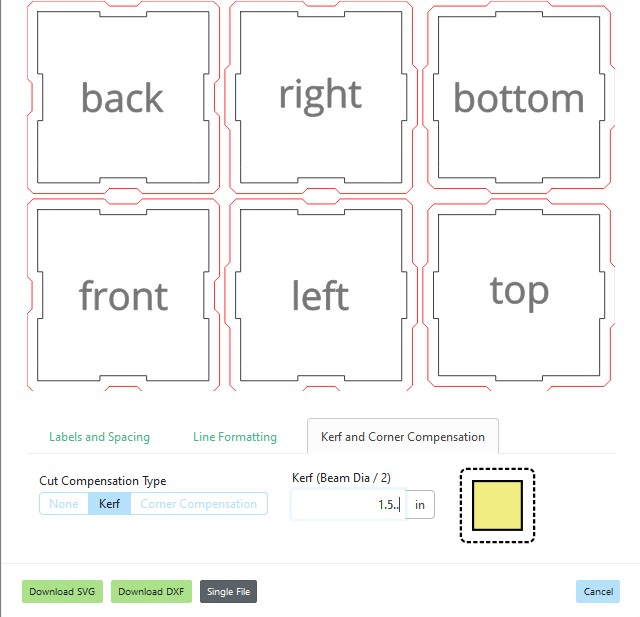
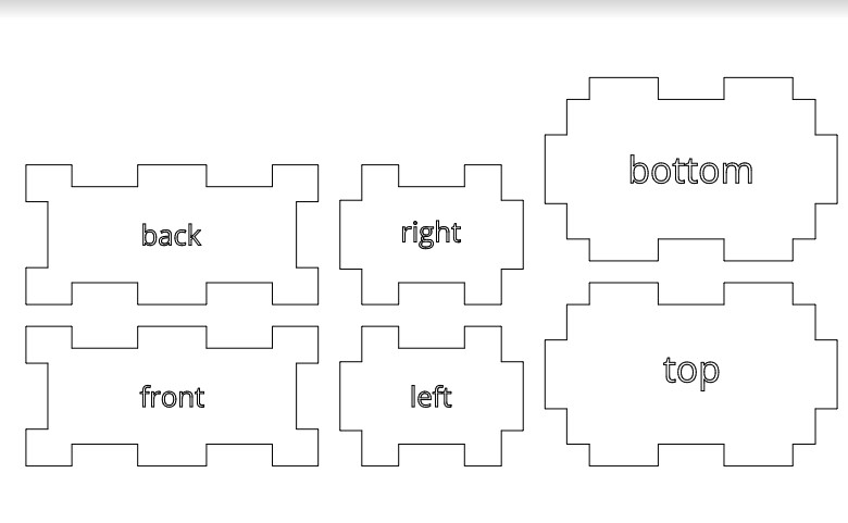
I designed the box using a website called MakerCase to make the box quickly and perfectly .
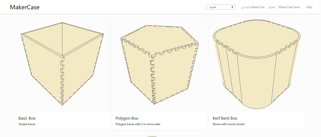
when you click to which design you want , you have to choose the dimmetions and if you what ot with jints or not :
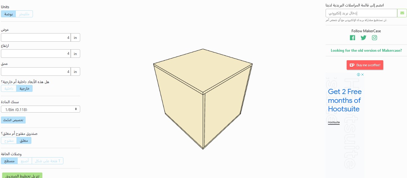
An important point if you want to make joints , which you have to make the kerft and you have to change the dimetions of them , to let the joints fit perfectly .
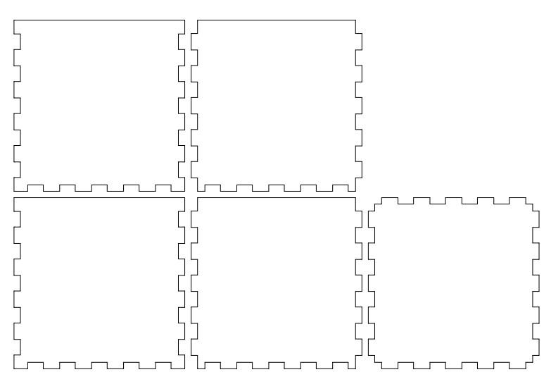
The sketch of the design before cutting
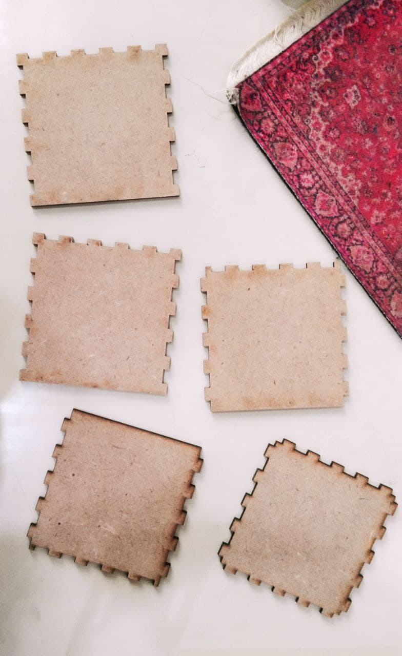
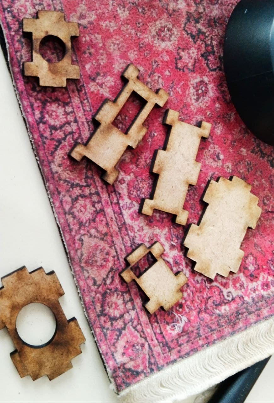
after i cut the design with the lasser cutterit became like this :
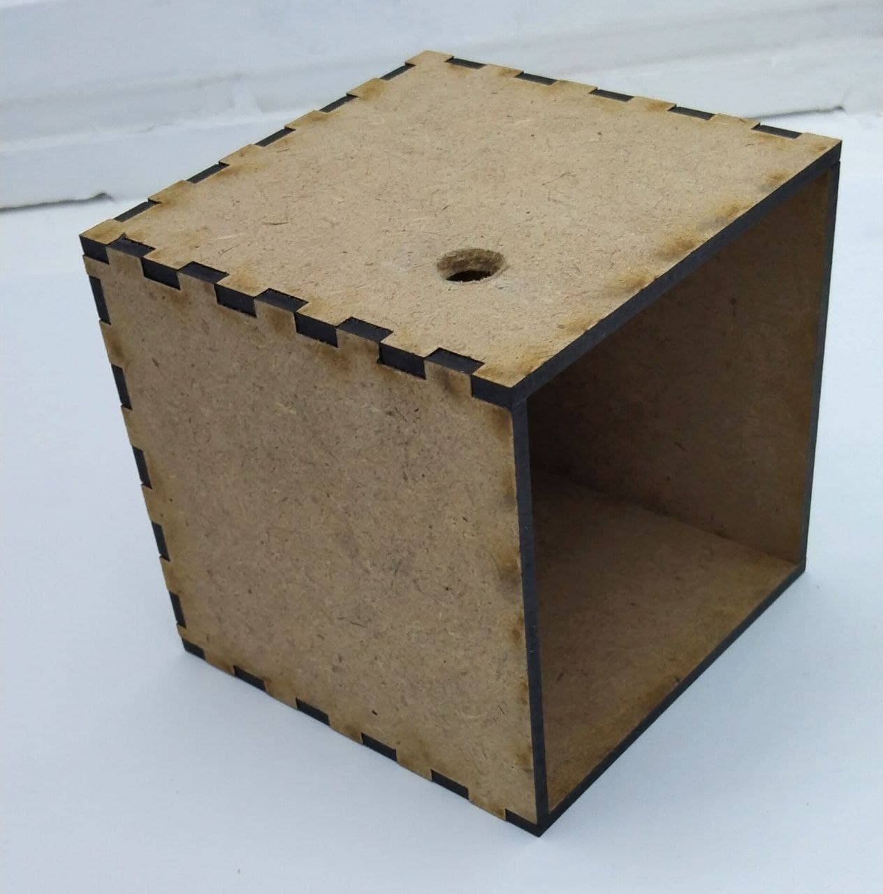
after jointing them , I made a hole to in the top of it , so I can pass the wires from .
Also for the arduino , i designed a small box to it using the same wibsite :
opening and closing mechanism
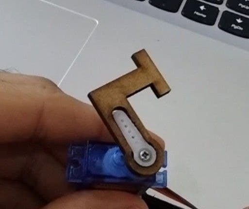
I made a shape that i can put on the Servo motore .
after i put it , it looked like :
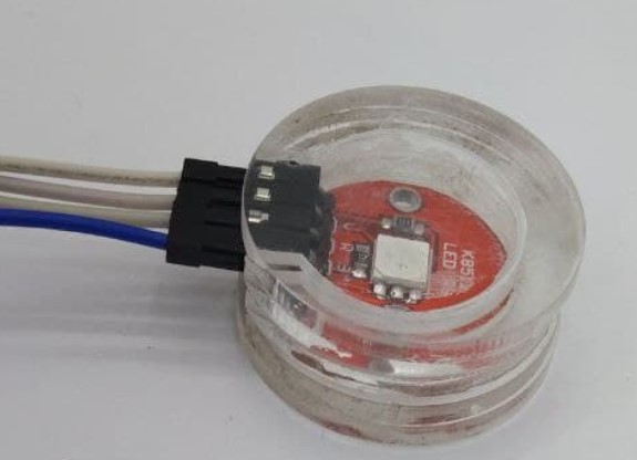
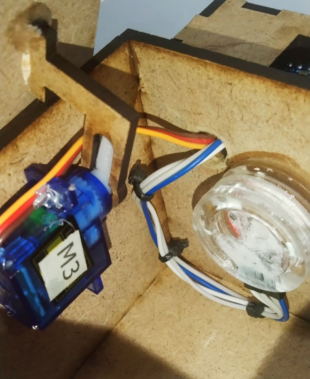
RGB case
for the RGB i made a clear cast to put it inside and to make the colors Separated perfectly .

The design files
The Electronics
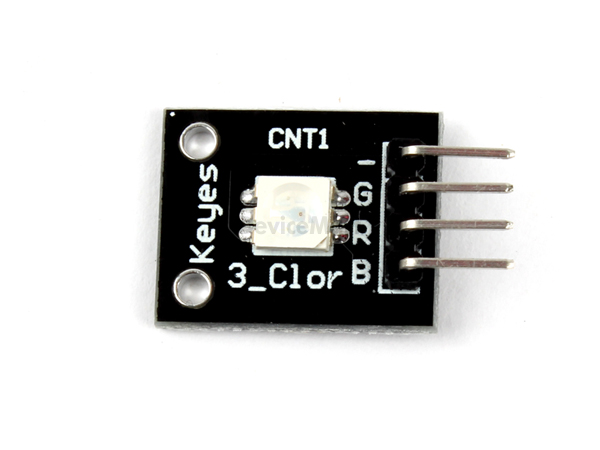
1 - RGB
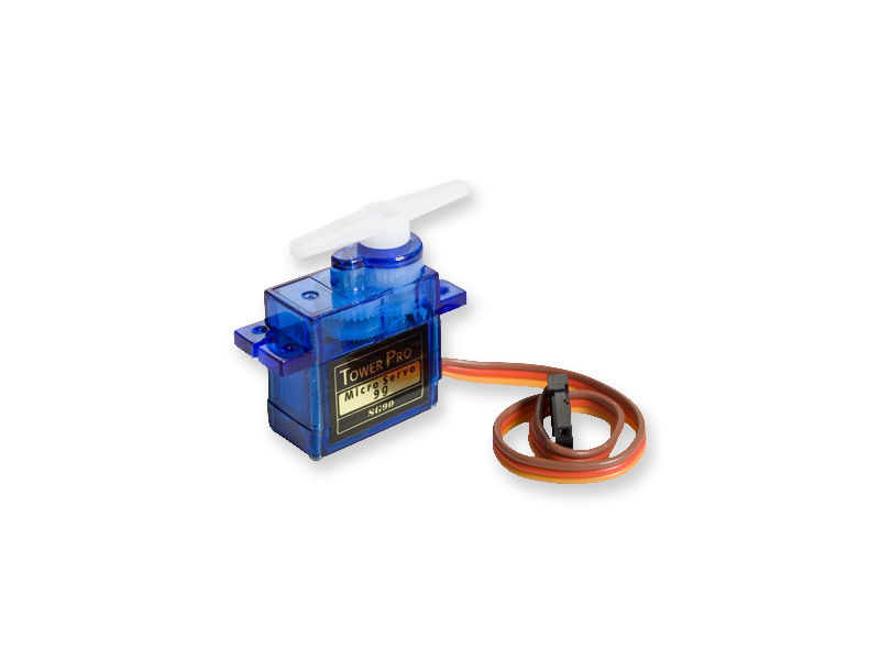
2 - servo motore
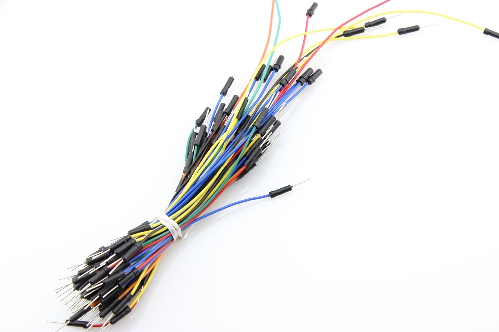
3 - wires
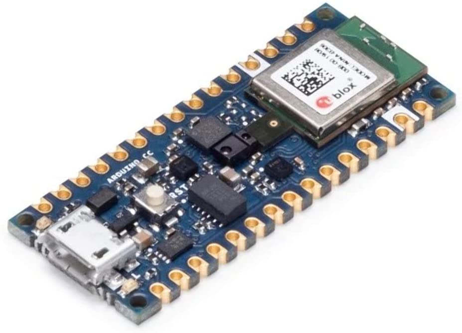
4 - arduino nano 33 sense
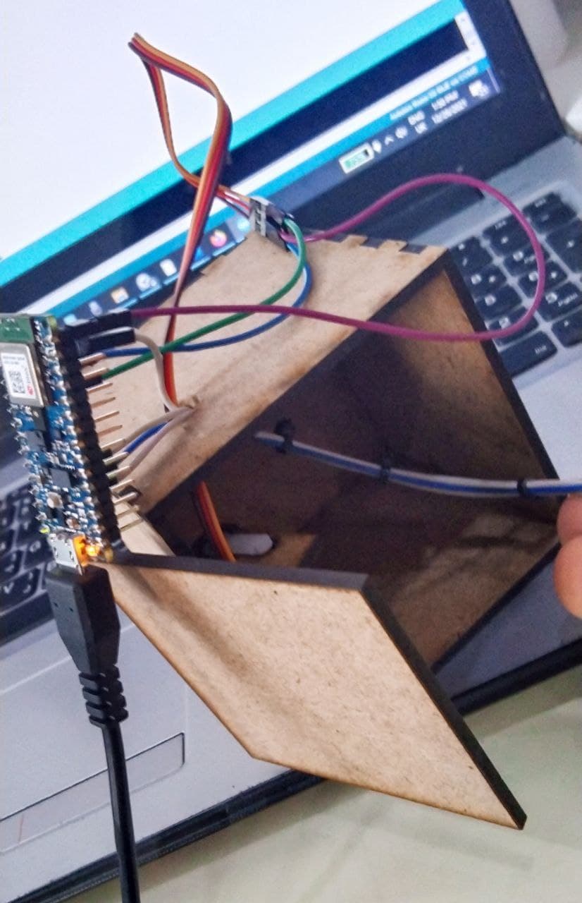
The electronics connection :
For the connection of the electronics i did the folowing :
The RGB connection :
I connect the RGB as in the photo :
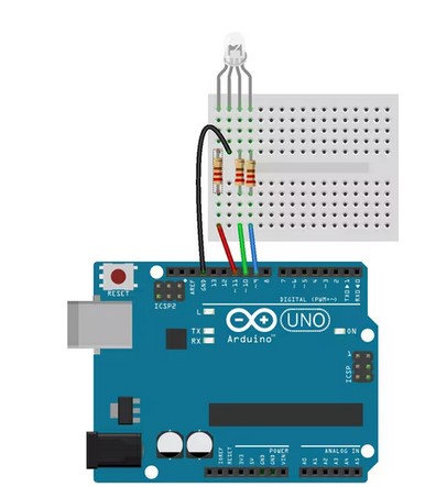
I connect R with pin 11 I connect G with pin 9 I connect B with pin 10 I connect the ground with the ground on the arduino
The Servo motore connection :
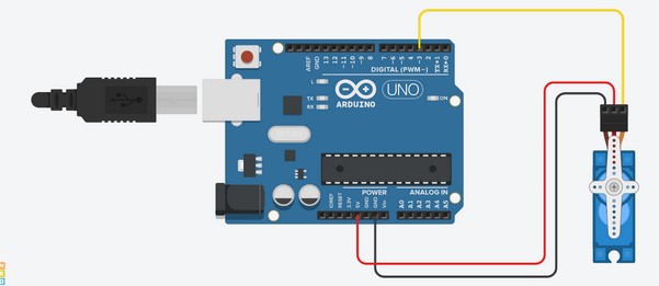
The Yallow wire I connected it with D3 pin. The Red wire I connected it with VIn pin. The Dark wire I connected it with ground pin.
The Software (Arduino Program)
In This part i had to focus on three main programs :
1 - The Bluetooth connection (BLE) . 2 - The color sensor . 3 - The servo motore .
The Bluetooth connection (BLE)
The Bluetooth connection was the hardest part , because i have to write a code that it will allow me to connect the arduino with the phone . I found an example in the internet , about the BLE code but it was to turn on and off a light .
The Explanation of the code
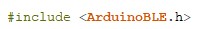
Here is the library that it has to be included in the programe to make the BLE works .
Here is a thing called UUID it is an important thing it helps the identifying information to the resevers .

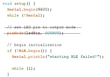
Here is the situp loop , i did not change anything in it , just I deleated the light code , because i will not use it in my project .
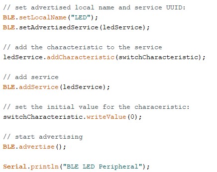
Here we had to name our device and to advertise it and to add the characteristics to the services
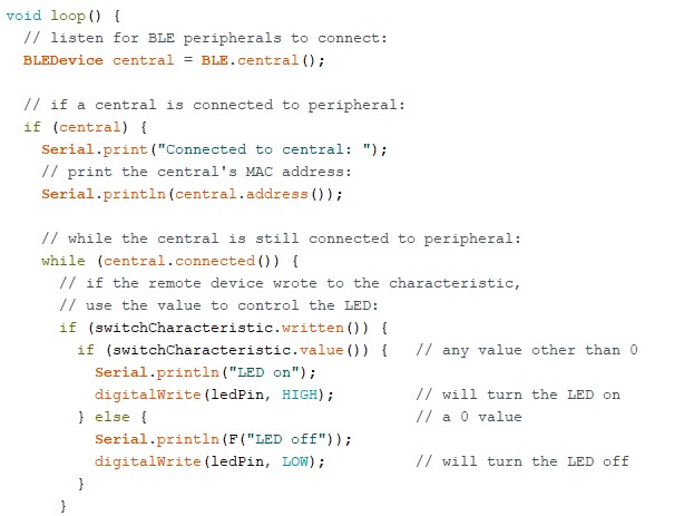
Here I had just to focus on the light part specially in the while loop while (central.connected()) because it refere that if the Bluetooth connected i want the Arduino to do a specific order , this means that the whole the work will be in it .
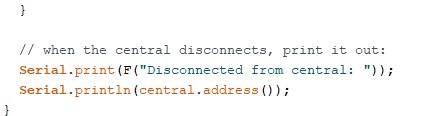
Here the code means if the Arduino became disconnected , write Disconnected from central for me .
This code is the base of the final code , because this code will allow me to work on the BLE
The color sensor
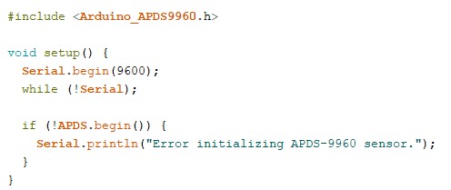
For the color sensor we have to install a librabt called APDS9960
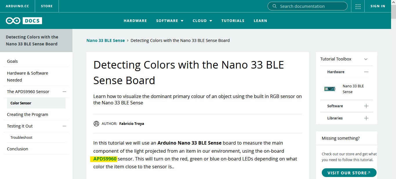
Detecting Colors with the Nano 33 BLE Sense Board
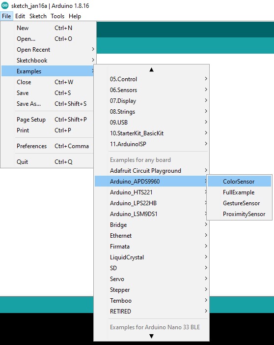
After installing the library we just have to follow these steps to take the code :
The Explanation of the code
Here we have the library that we installed and we have the situp loop of the code .
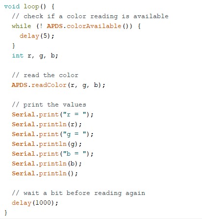
In this loop the R means Red , the G means Green and the B means Blue , The role of this loop is to difine the amount of each color that the sensor is detecting in each second .
Adding the color sensor code to the BLE code .
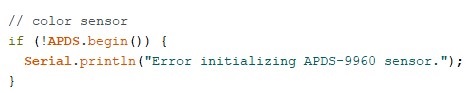
I added this code that i found in the setup of the color sensor code to situp of the BLE code .
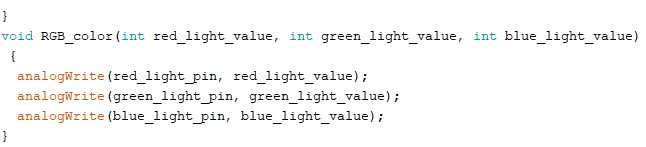
The RGB code is really important in this point because will will connect the RGB with the color sensor. I found an example for the RGB code
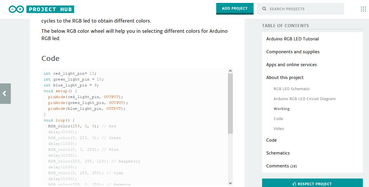
Also the code of defining the pins of the RGB , because we will connect the color sensor with the RGB Before the situp loop
I added this code that i found in the setup of the RGB code to situp of the BLE code .
I added this code in the main loop in the color sensor code to main loop of the BLE code and i change the duration of detecting the colors to one second .
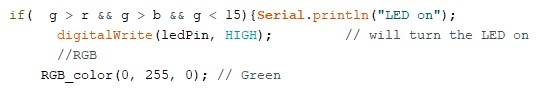
I added this if conditiont to let the RGB works in a specific conditiont , which are :
1 - when the amount of green color is less than 15 and the green color is more than the red and blue color , the RGP will turn Green color .
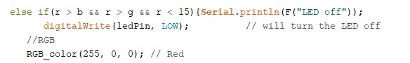
2 - when the amount of red color is less than 15 and the red color is more than the green and blue color , the RGP will turn red color .
3 - if there is no one of these conditionts the color well be between Blue and green
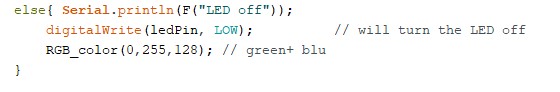
I put this code of the RGB in the end of the main code , as it is done in the RGB code
The servo motore
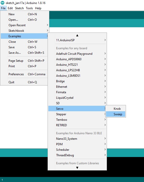
First I had to install a library called Servo.h

The library includes an example called Sweep we can use this example to make our motore works .
Adding the servo motore code to the BLE code .
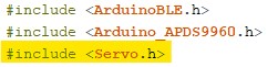
I included the library with the libraries
These codes I included them Before the situp loop
I added this code that i found in the setup of the Servo motore code to setup of the BLE code .
I included this code in the main loop which meens when the Bluetooth is connected and it is reseved a value equal to anything except zero , the motore will move a specific degree . I kept it 70 dgree because i saw it is the best degree to open the door that I make , and it is changable .

I put this code in the main loop which meens when the Bluetooth is connected and it is reseved a value equal zero , the motore will move with 70 degree back .

The final code
`
#include <ArduinoBLE.h>
#include <Arduino_APDS9960.h>
#include <Servo.h>
BLEService ledService("19B10000-E8F2-537E-4F6C-D104768A1214"); // BLE LED Service
// BLE LED Switch Characteristic - custom 128-bit UUID, read and writable by central BLEByteCharacteristic switchCharacteristic("19B10001-E8F2-537E-4F6C-D104768A1214", BLERead | BLEWrite);
const int ledPin = LED_BUILTIN; // pin to use for the LED
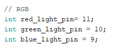
// RGB
int red_light_pin= 11;
int blue_light_pin = 9;
// servo
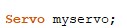
Servo myservo; // create servo object to control a servo
// twelve servo objects can be created on most boards
int pos = 0; // variable to store the servo position
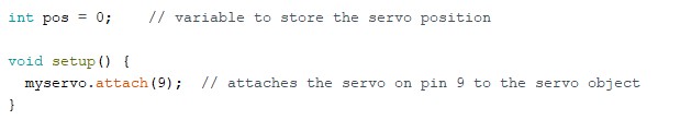
void setup() {
Serial.begin(9600);
while (!Serial);
// set LED pin to output mode
pinMode(ledPin, OUTPUT);
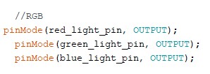
//RGB
pinMode(red_light_pin, OUTPUT);
pinMode(green_light_pin, OUTPUT);
pinMode(blue_light_pin, OUTPUT);
// color sensor
if (!APDS.begin()) {
Serial.println("Error initializing APDS-9960 sensor.");
// servo
myservo.attach(3); // attaches the servo on pin 9 to the servo object
// BLE
if (!BLE.begin()) {
Serial.println("starting BLE failed!");
while (1);}
// set advertised local name and service UUID:
BLE.setLocalName(" The box ");
BLE.setAdvertisedService(ledService);
// add the characteristic to the service
ledService.addCharacteristic(switchCharacteristic);
// add service
BLE.addService(ledService);
// set the initial value for the characeristic:
switchCharacteristic.writeValue(0);
// start advertising
BLE.advertise();
Serial.println("BLE LED Peripheral");}
void loop() { //BLE
// listen for BLE peripherals to connect:
BLEDevice central = BLE.central();
// if a central is connected to peripheral:
if (central) {
Serial.print("Connected to central: ");
// print the central's MAC address:
Serial.println(central.address());
// while the central is still connected to peripheral:
while (central.connected()) {
// if the remote device wrote to the characteristic,
// use the value to control the LED:
if (switchCharacteristic.written()) {
if (switchCharacteristic.value()) { // any value other than 0
Serial.println("LED on");
digitalWrite(ledPin, HIGH); // will turn the LED on
//RGB
RGB_color(0, 255, 0); // Green
// servo
pos = 0; pos <= 70; pos += 1;
myservo.write(pos); // tell servo to go to position in variable 'pos'
}
else { // a 0 value
Serial.println(F("LED off"));
digitalWrite(ledPin, LOW); // will turn the LED off
//RGB
RGB_color(255, 0, 0); // Red
// servo
pos =70; pos >= 0; pos -= 1;
myservo.write(pos); // tell servo to go to position in variable 'pos'
}
}
}
// when the central disconnects, print it out:
Serial.print(F("Disconnected from central: "));
Serial.println(central.address());
}
//color sensor
// check if a color reading is available
while (! APDS.colorAvailable()) {
delay(5);
}
int r, g, b;
// read the color
APDS.readColor(r, g, b);
// print the values
Serial.print("r = ");
Serial.println(r);
Serial.print("g = ");
Serial.println(g);
Serial.print("b = ");
Serial.println(b);
Serial.println();
// wait a bit before reading again
delay(1000);
// color sensore
if( g > r && g > b && g < 15){Serial.println("LED on");
digitalWrite(ledPin, HIGH); // will turn the LED on
//RGB
RGB_color(0, 255, 0); // Green
// servo
pos = 0; pos <= 70; pos += 1;
myservo.write(pos); // tell servo to go to position in variable 'pos'
}
else if(r > b && r > g && r < 15){Serial.println(F("LED off"));
digitalWrite(ledPin, LOW); // will turn the LED off
//RGB
RGB_color(255, 0, 0); // Red
// servo
pos =70; pos >= 0; pos -= 1;
myservo.write(pos); // tell servo to go to position in variable 'pos'
}
else{ Serial.println(F("LED off"));
digitalWrite(ledPin, LOW); // will turn the LED off
RGB_color(0,255,128); // green+ blu
}
}
void RGB_color(int red_light_value, int green_light_value, int blue_light_value){
analogWrite(red_light_pin, red_light_value);
analogWrite(green_light_pin, green_light_value);
analogWrite(blue_light_pin, blue_light_value);}
`
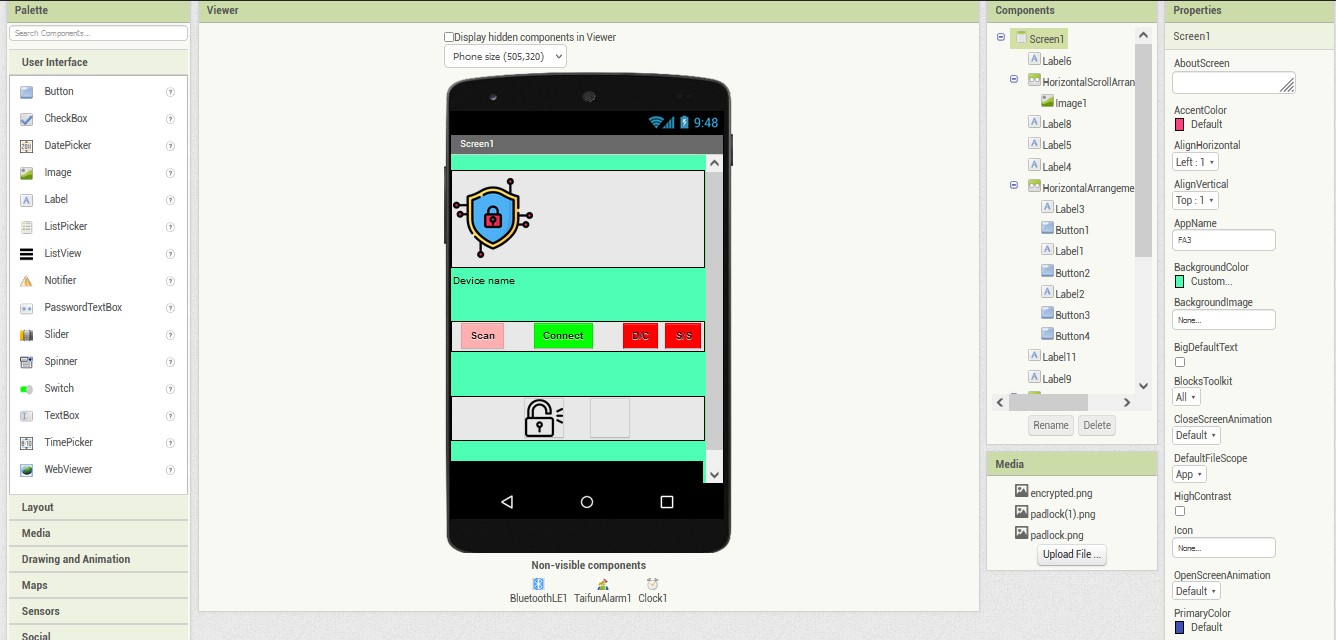
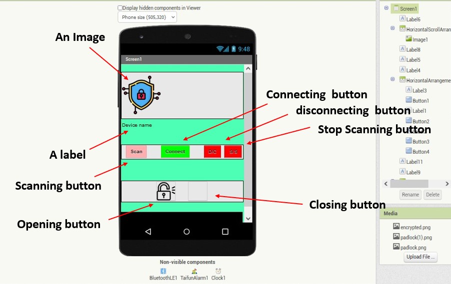
The applecation (Smart box)
In the applecation i used the same base of week 7 but i changed the design of it little bit .
The design of the applecation :
The application files
apk : (download the application)
aia : (download the application)
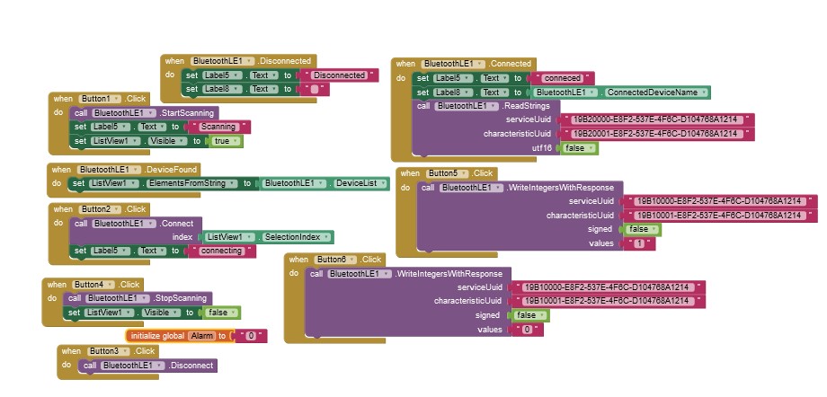
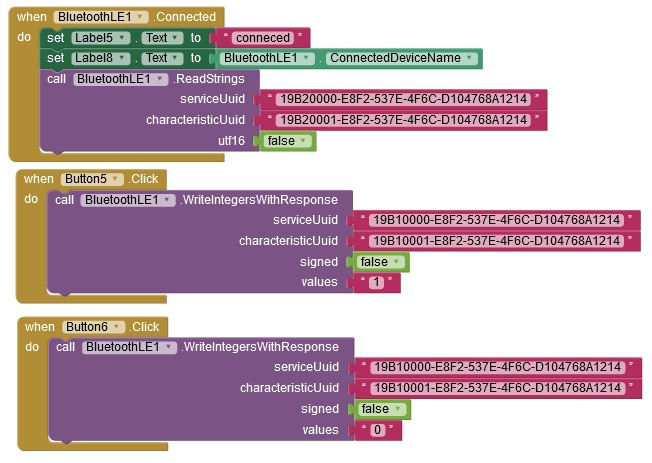
The blocks :
The blocks are explained in week 7
I had to use the UUID to make the phone knows the type of the information that i am sending (Be sure that the UUID that you are using is the same one in the arduino programe)

The final result (The Smart Box)
At the end , when joint and connect everything .
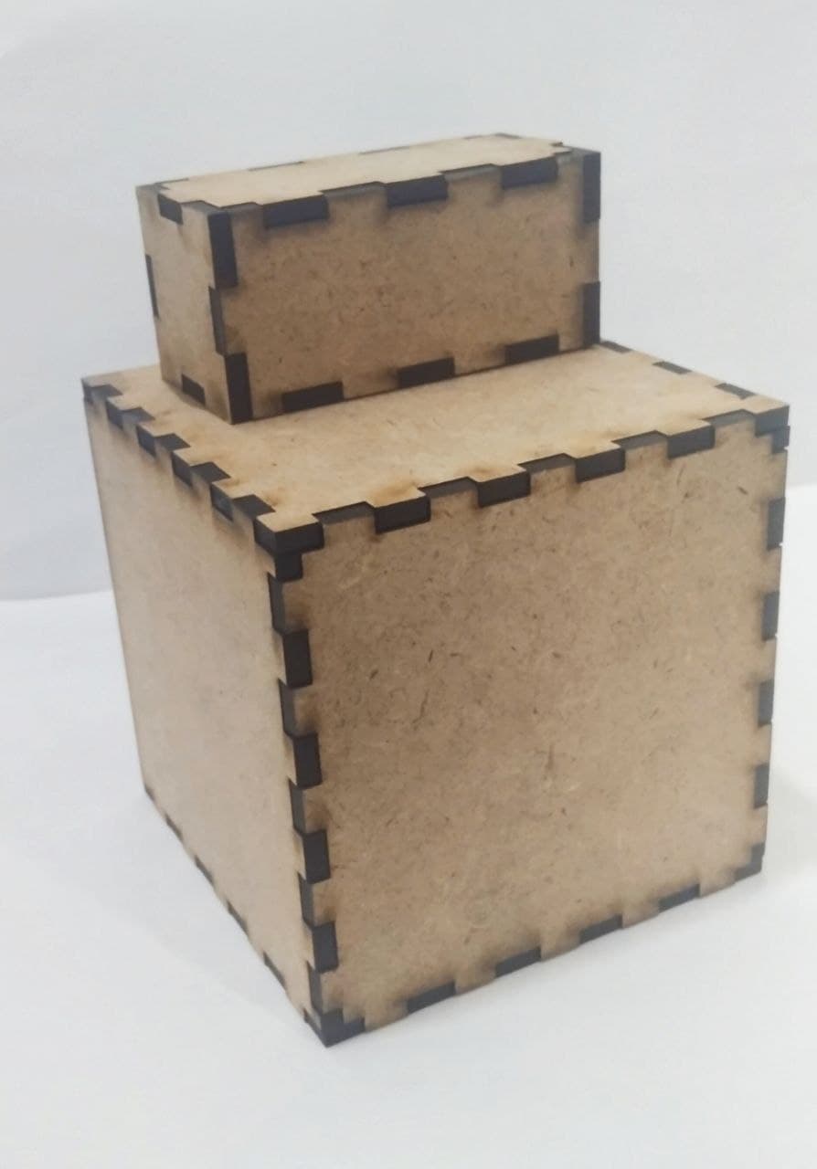
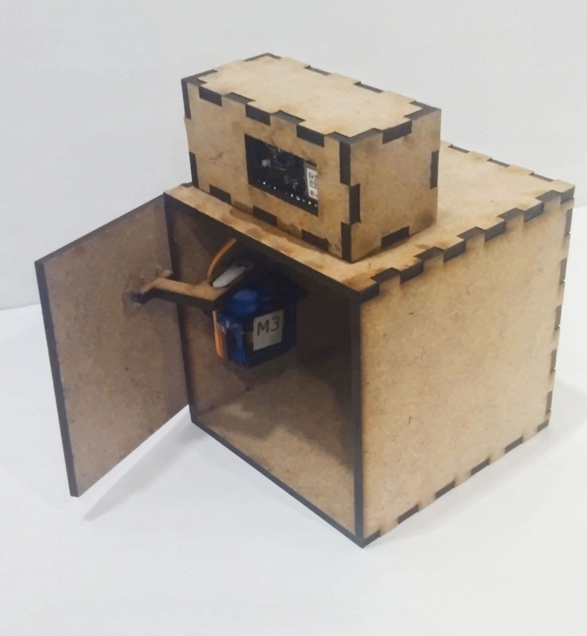
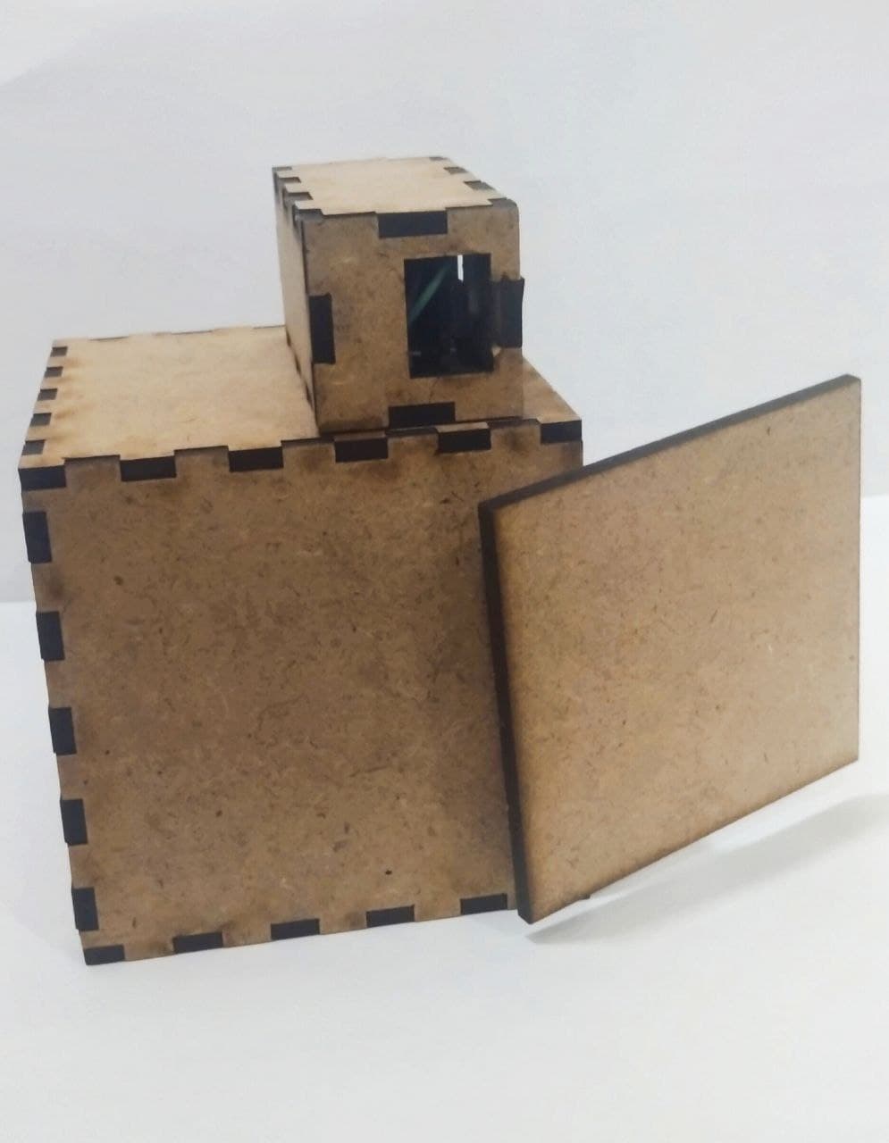
it became like this :