FINAL PROJECT
For two weeks, me and Fatima worked on our final project. At first, we thought about making a simple drone but due to lack of some special light motors, we had to decide on something else. I proposed a second idea which was to make an underwater drone that supports camera and specialized sensors to measure pollution. Unfortunately, we dismissed the idea due to having limited time and decided to make a simple boat that can be controlled with a smartphone.
Research
We started by watching videos and searching online for similar projects. Also we decided to search about the materials and components involved along with their costs. We also searched about the theoretical concepts related to boats.
Materials and Components
The table below shows the materials and components used and their costs along with their components:
| Qty | Description | Price | Link | Notes |
|---|---|---|---|---|
| 1 | Adafruit Feather | $37.50 | https://www.adafruit.com/product/4516 | |
| 1 | 9 Volt battery | $6.19 | http://amazon.com/test | |
| 2 | Motors | $5.51 | http://amazon.com/test | |
| 2 | DC motors | $4.50 | http://amazon.com/test | |
| 1 | L298N Motor Driver | $11.49 | http://amazon.com/test | |
| 1 | Breadboard | $5.99 | http://amazon.com/test | |
| 20 | Jumpers | $3.40 | http://amazon.com/test | |
| 1 | WaterProof Tape | $3.00 | http://amazon.com/test | |
| 1 | Foamboard |
The components were not hard to find and most of them were available at the lab.
Theory and Calculations
The minimum volume required to keep the boat afloat is given by:
V = m/(Dw-Db)
We decided to use Foamboard to make the body for the boat which has a density of 48kg/m^3. We chose the maximum mass to be 2kg and performed the calculations to get the minimum volume:
V = 0.002m^3
Circuit And Coding
We decided to start with the circuit and coding because this step will have a huge impact on the final design.
I started by testing the rotation direction for motors. the motor driver allows us to control the direction of rotation for both motors. The image below shows the pins on the L298N motor driver:
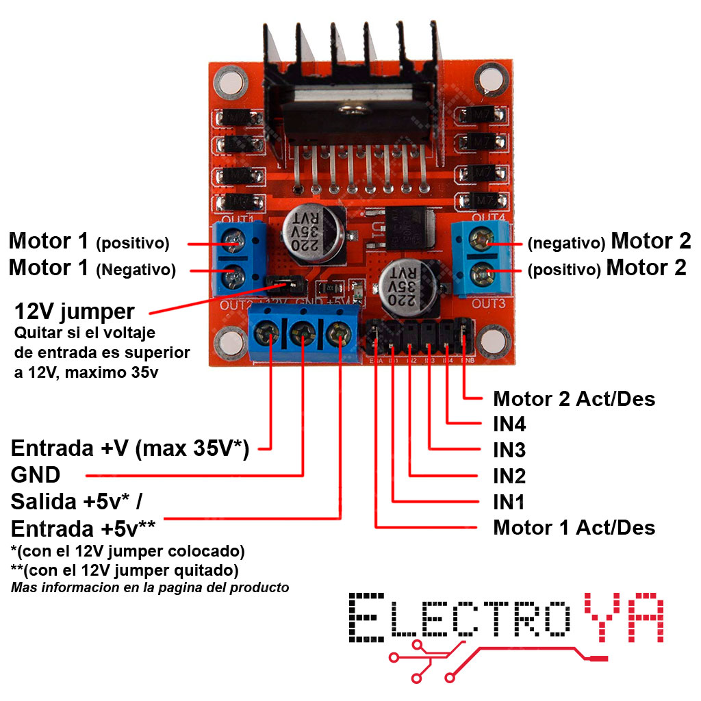
The rotational direction of motors is controlled by the 4 IN pins. IN 1 and 2 control the first motor while the other two pins control the second motor.
I assembled the circuit in Tinker CAD first as shown below:
.png)
Then, I started writing the code. I tested the rotation directions of motors and wrote the configurations of pins that produce forward, left, right, and reverse motion depending on the coupled directions of rotations which are related to the states of pins.
.png)
Next, I started setting up the code that will allow us to control the boat using my android phone. From Examples, I chose the controller example code:
.png)
In order to link the phone to the adafruit board, we needed to download the Bluefruit app. I then uploaded the controller code to my board and then opened the app. From the app I connected to the Adafruit board and chose Controller then Control Pad.
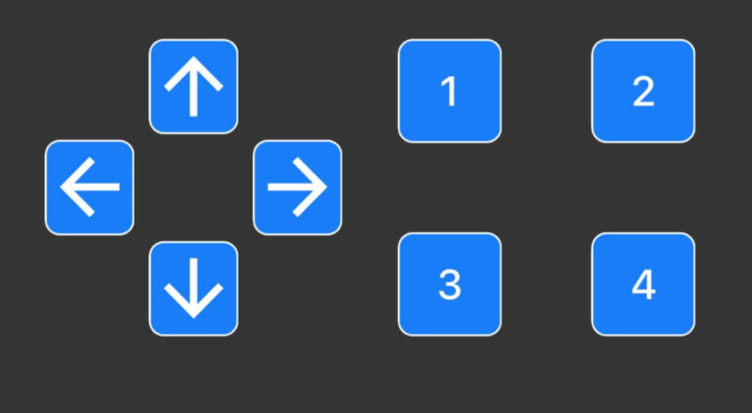
after establishing the bluetooth connection, The serial monitor displayed the number of each button when pressed. the numbers 5,8,7, and 6 are associated with buttons up, right, left, and down respectively therefore I had to modify the code so that pressing each button would turn on specific configurations of motor rotations associated with each direction. Therefore, To achieve this, I used if statements to link each button to a certain configuration of pins in order to produce motion in the same direction as the arrow on the button.
.png)
After that, I uploaded the code into my Adafruit board and the coding process was finished
Design
After we were done with the coding and the circuit, we moved on to the design. we used Tinker CAD to make a 3D design for our boat. The video below shows the process:
After completing the 3D design and exporting it, we had to convert it to a 2D design to laser cut it with the laser cutting machine. We uploaded the 3D file in a website called papermaker and it automatically converted the 3D design to a 2D design that can be cut using the laser cutting machine.
.png)
The 2D design consists of two parts, the body and the top cover. We exported an svg file of the 2D design, converted it to a dxf file and then started cutting it with laser.
You can download both the 3D design and the 2D designs.
We chose this design specifically because it allowed us to achieve maximum floating with the weight we needed to load.
Assembling
After being done with coding and design, we started assembling the parts.