COMPUTER CONTROLLED CUTTING
This week, I have been introduced to computer controlled cutting. I was introduced to two different machines, a laser cutter and a Vinyl machine.
\frac{V_{min}}{V^3}
Laser Cutting
SAFETY REGULATIONS
the laser cutting machine can produce laser beams hot enough to instantly penetrate various materials. This is why some important safety measures need to be taken into account:
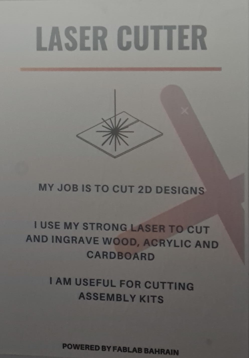

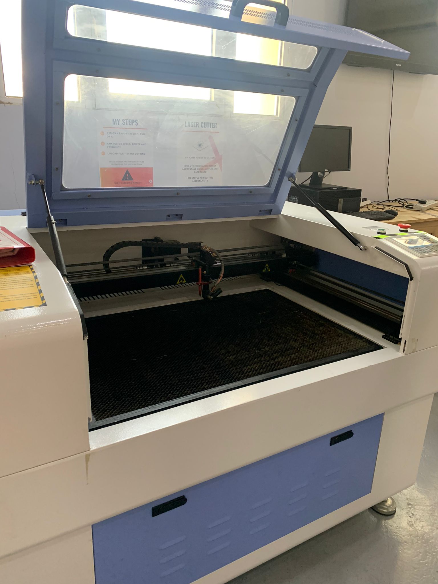
We started this week by learning about the laser cutting machine and the process of choosing the right settings for cutting the material to form the desired shapes. The laser cutting machine is large and is connected via a USB cable to a computer through which we can adjust our designs. The machine can also be used for engraving.
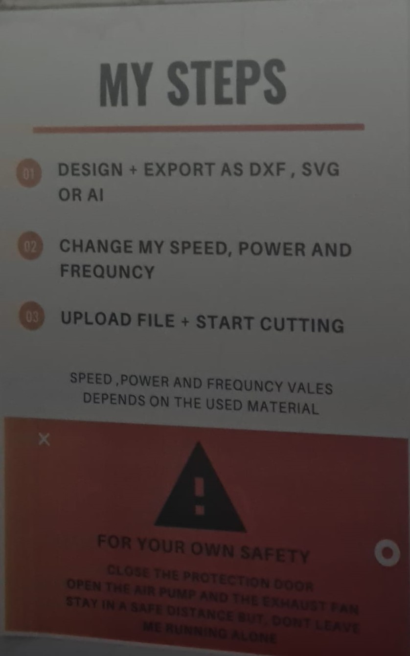
The settings are chosen from a specialized software called RD-works.
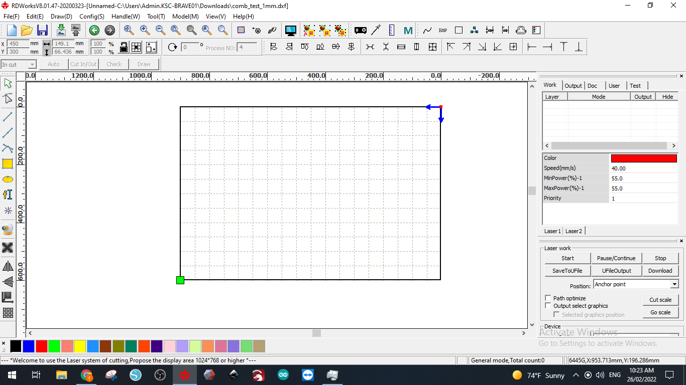
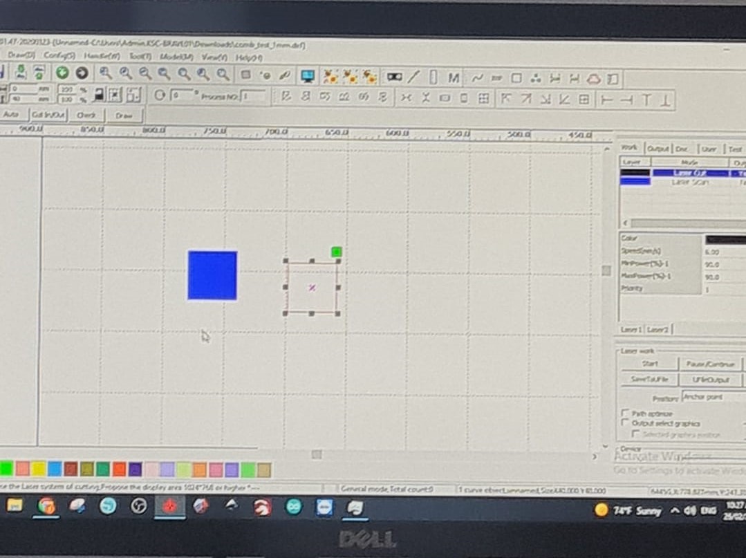
Design files need to be in DXF format which can be exported from a CAD software such as Fusion 360 or autoCAD. Once a file is opened in the software, The position of the desired parts can be selected. Also, the designs can be modified. Once everything is set, the user needs to press the DOWNLOAD button to transfer the design from the pc to the machine via the USB cable.
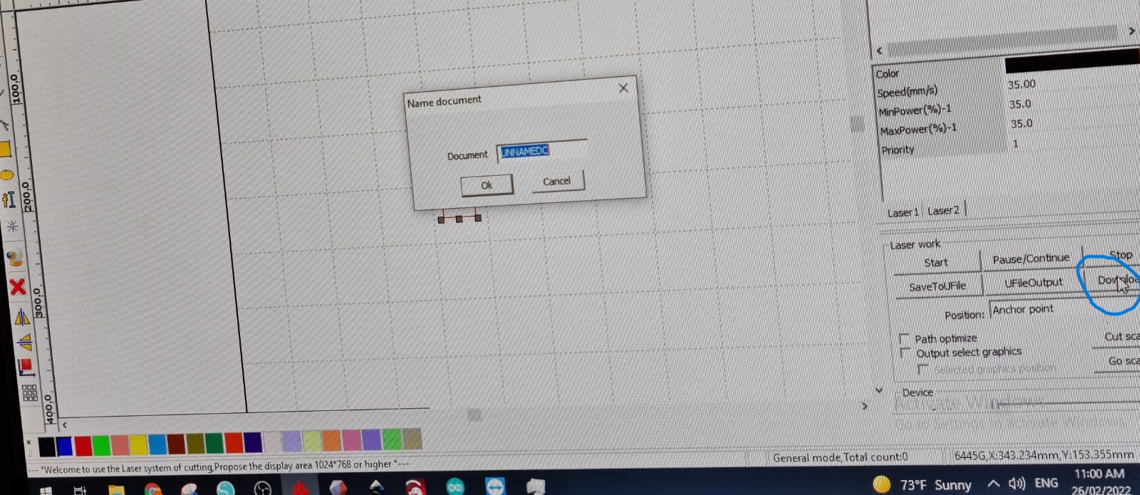
The file needs to be saved with a name in order to access it later from the machine’s interface.
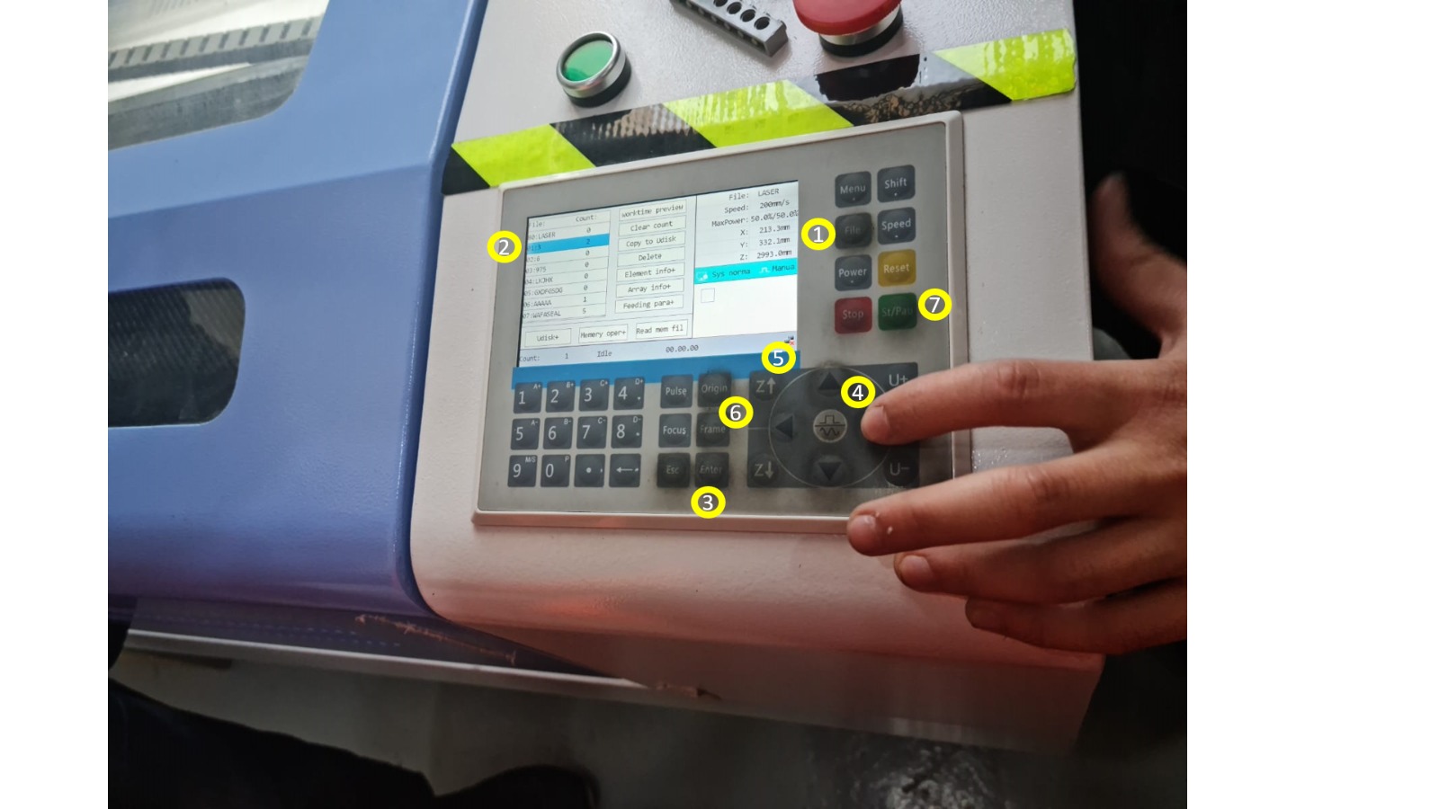
Before starting the cutting process, these steps must be followed:
Testing The Machine
We started to safely play with the machine in order to become familiar with the controls by moving the laser cutting head and calibrating the base. For some reason, the laser head produces slightly less accurate results when operating on the right side. This is why we chose to use the right side for cutting in order to choose the right settings to increase the accuracy (since producing good results on the less accurate side reflects greater precision from the user’s side).
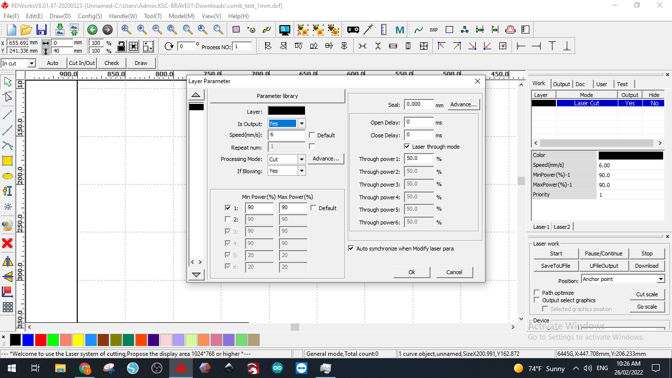
The settings for each type of material need to be chosen in a way that produces clean cuts with less burning on the edges. The two main factors that can affect the quality of cutting are the percentage of the laser beam power and the speed of the moving laser head. These two parameters need to be selected in a way that minimizes defects and burning.
Testing The Power Percentage And Speed
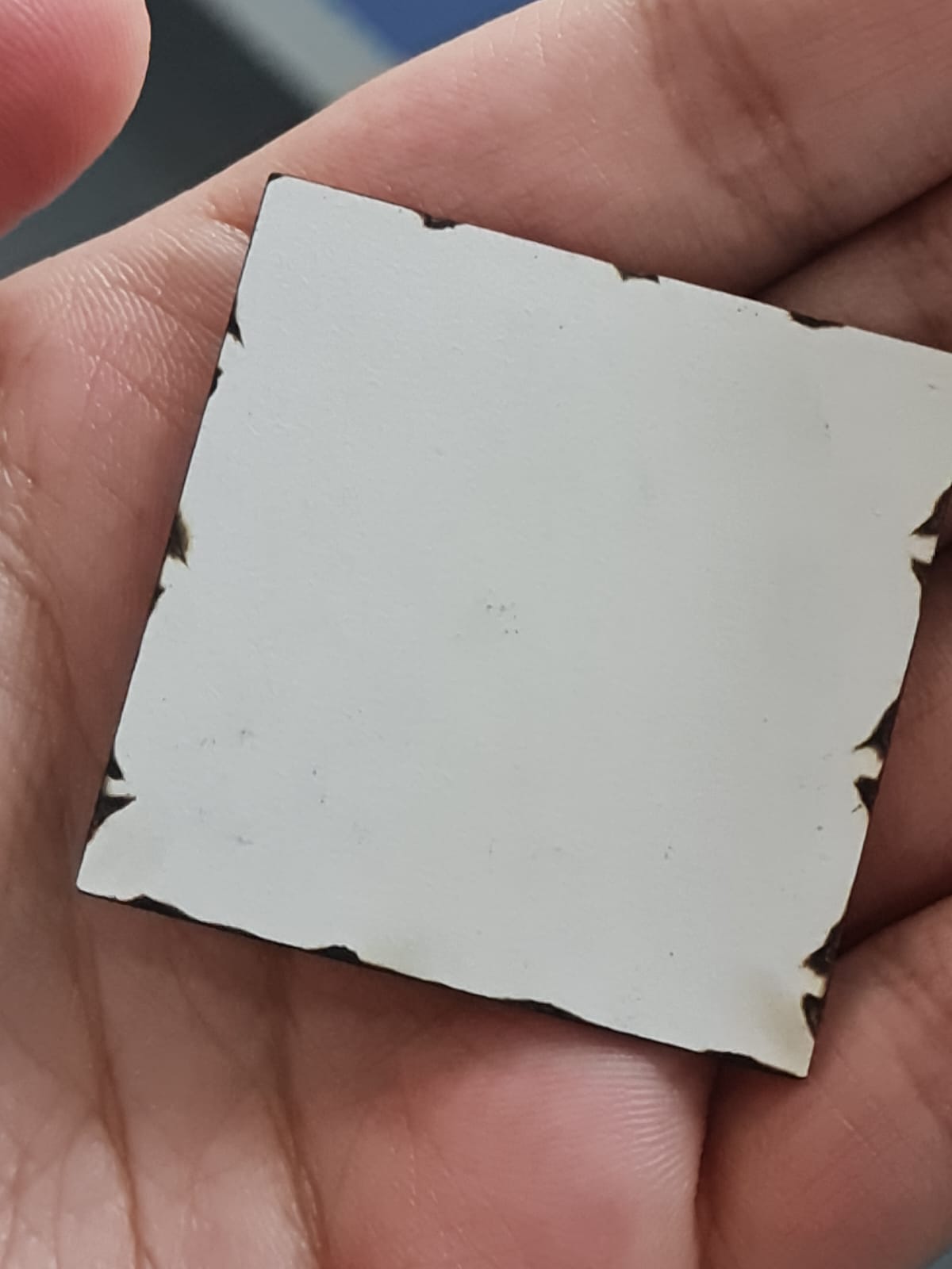
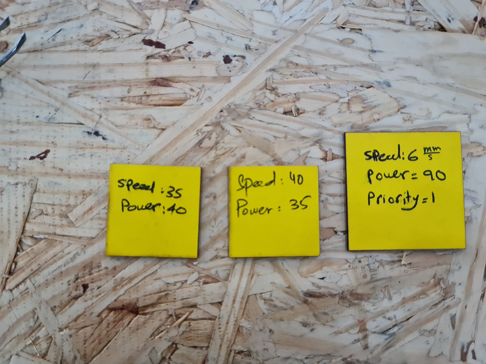
The testing process began with randomly setting the power and speed to see what would happen. For the first trial, we chose 90% power percentage and a speed of 6 mm/s.
We used a thin yellow sheet to cut a square
The final square had noticeable defects and burns on the edges which made us look for better settings
For the second trial, we set the speed to 35 mm/s (to minimize exposure time and thereby the burning) and the power to 40%. This time, there were fewer burns and defects. Finally, I suggested a power of 35% and a speed of 40 mm/s. This reduced the burning and defects even more. The squares are shown below:
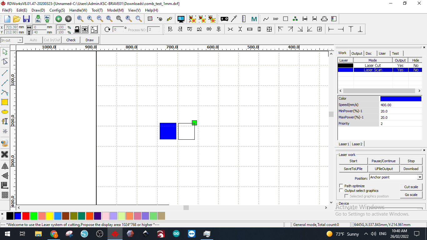
Next, we tested for engraving. We chose SCAN instead of CUT for the processing mode then set the power and the speed to be 20% and 400 mm/s respectively (enough power and speed to scratch the surface).
Press Fit
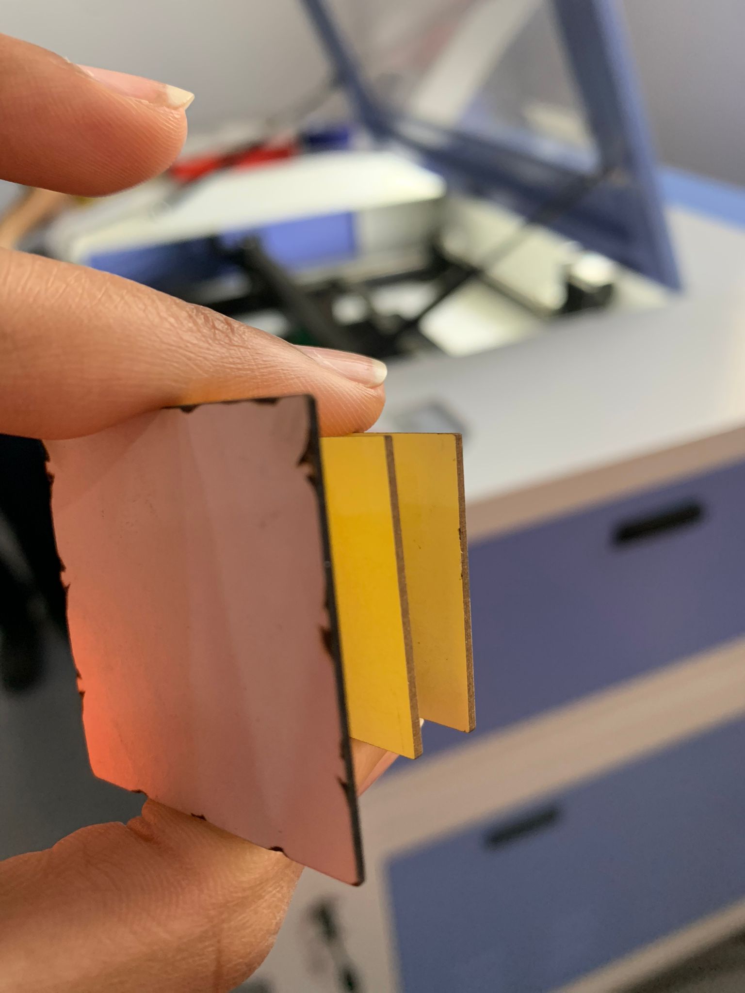
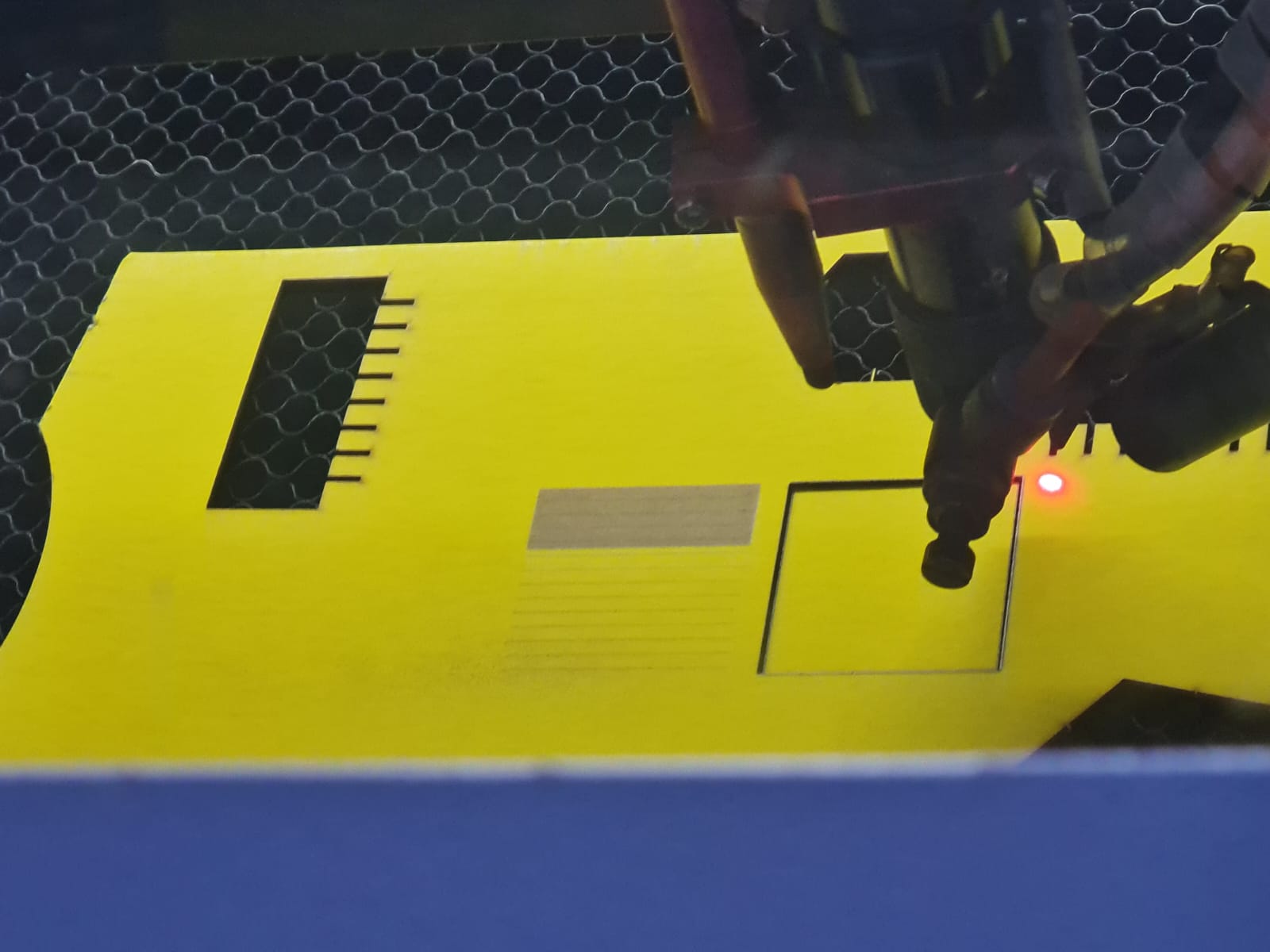
In order to perfectly assemble the laser cut parts, we needed to find the perfect thickness for attachment areas for the material in order to minimize the defects that might occur due to friction and compression. So we designed a Press Fit tool (sheet material calibrator) in order to find the perfect thickness for joints.
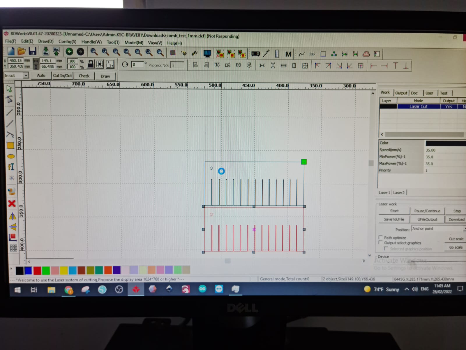
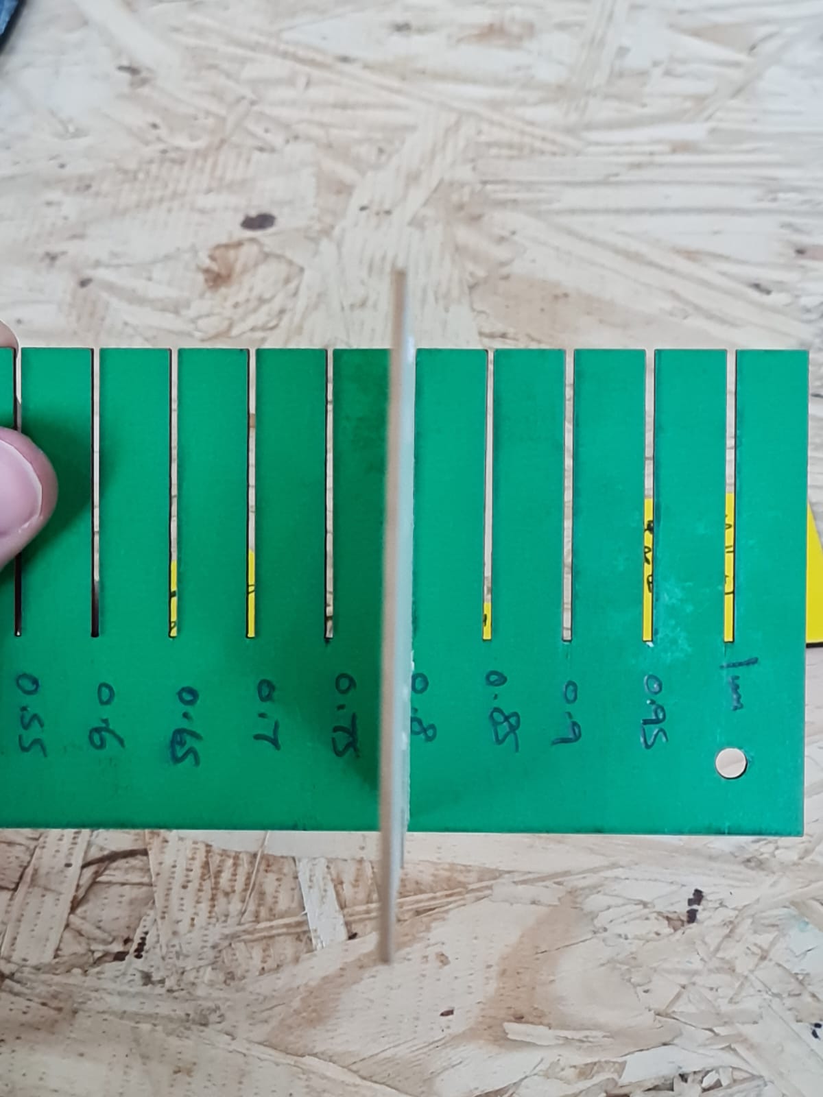
We then started the cutting process and ended up with these two pieces. After doing the fitting test, we all agreed that 0.8 mm was the most suitable thickness.
You can click here to further view our group work.
Vinyl Cutting
Also, we were introduced to the Vinyl cutting machine.
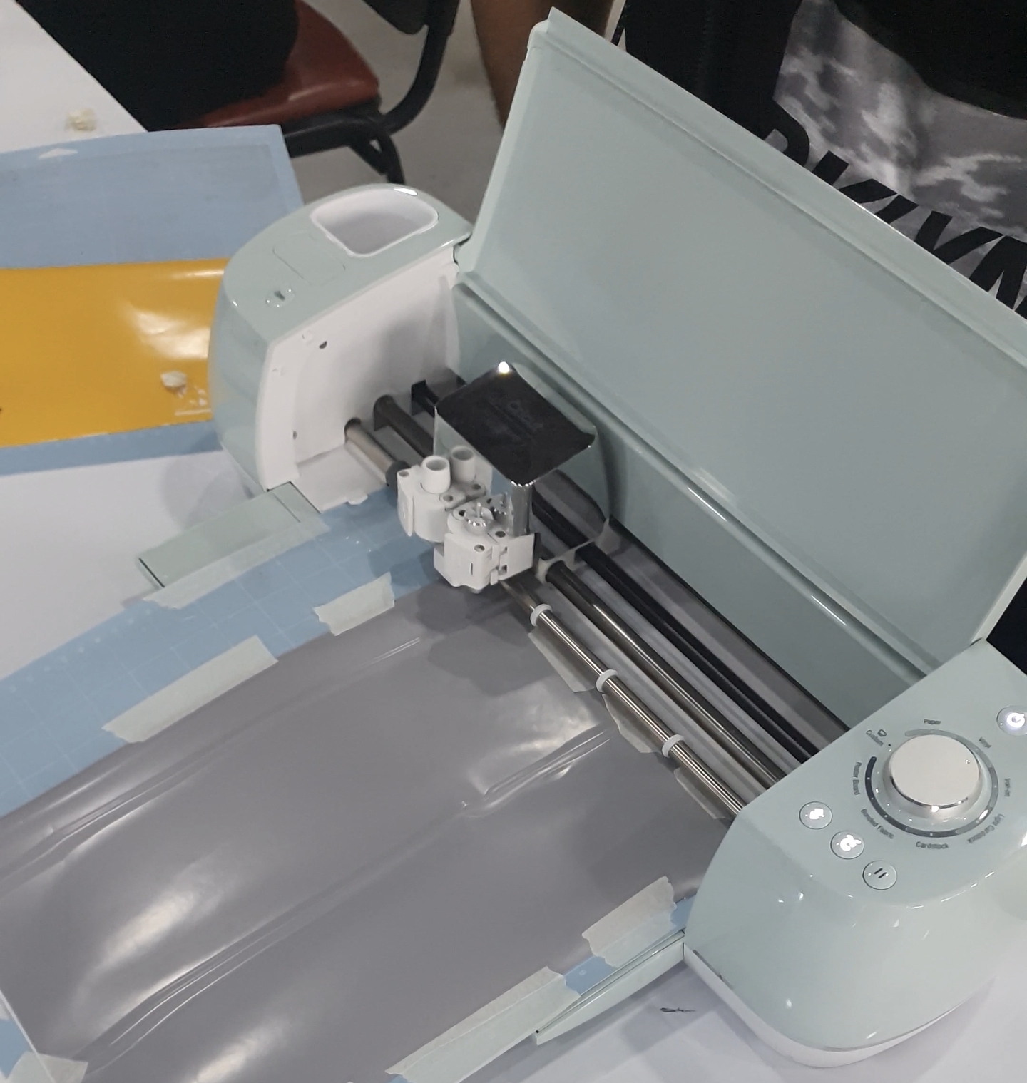
This machine can produce stickers designed by a computer. There are sticky sheets that can be attached on a special 12”*12” mat that needs to go through the Vinyl machine during the cutting process. During the cutting process, the machine will slowly pull the mat inside toward the cutting head that can move and cut in 1D so the sheet needs to be taped to the mat.
To use the Vinyl machine properly, the Cricut software must be downloaded.
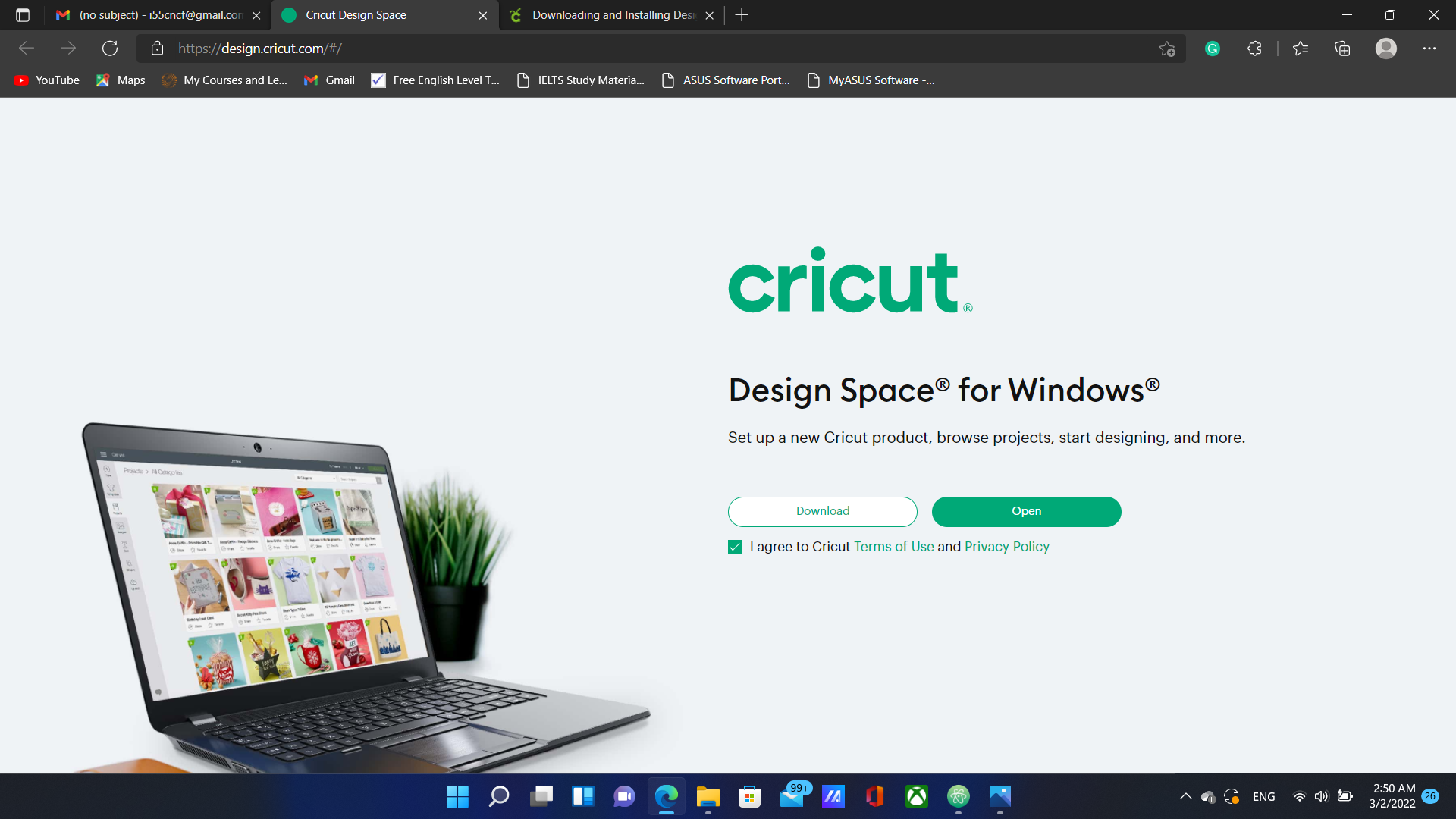
After that, users must upload their designs, go through some settings, connect their devices to the machine and start the process.
For me, I got way too excited and chose to make the Lagrangian of the standard model into a sticker.
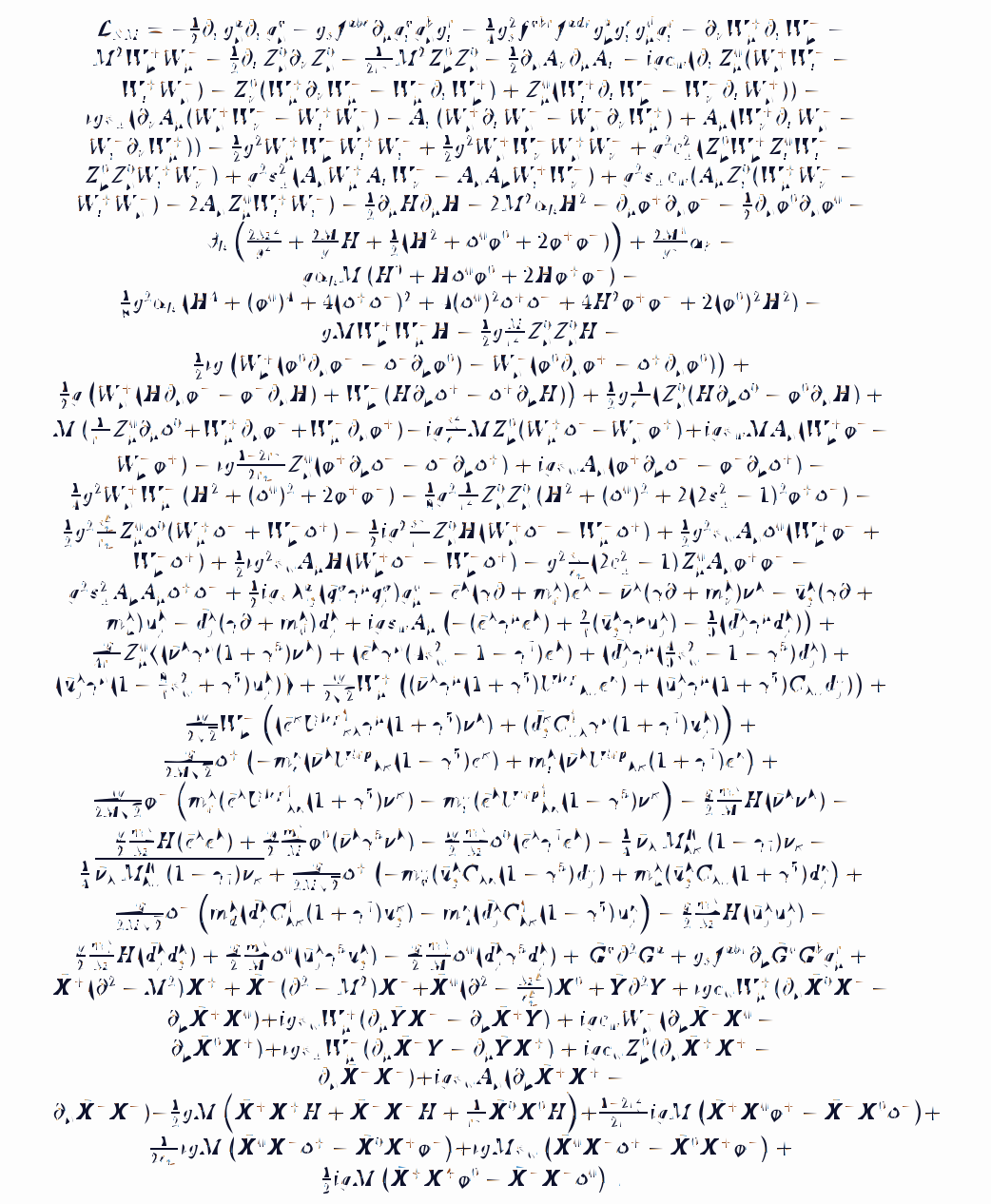
So I uploaded the image in Cricut and started the process as shown below:
Once I completed the steps, a loading screen appeared on my screen that showed the completion percentage.
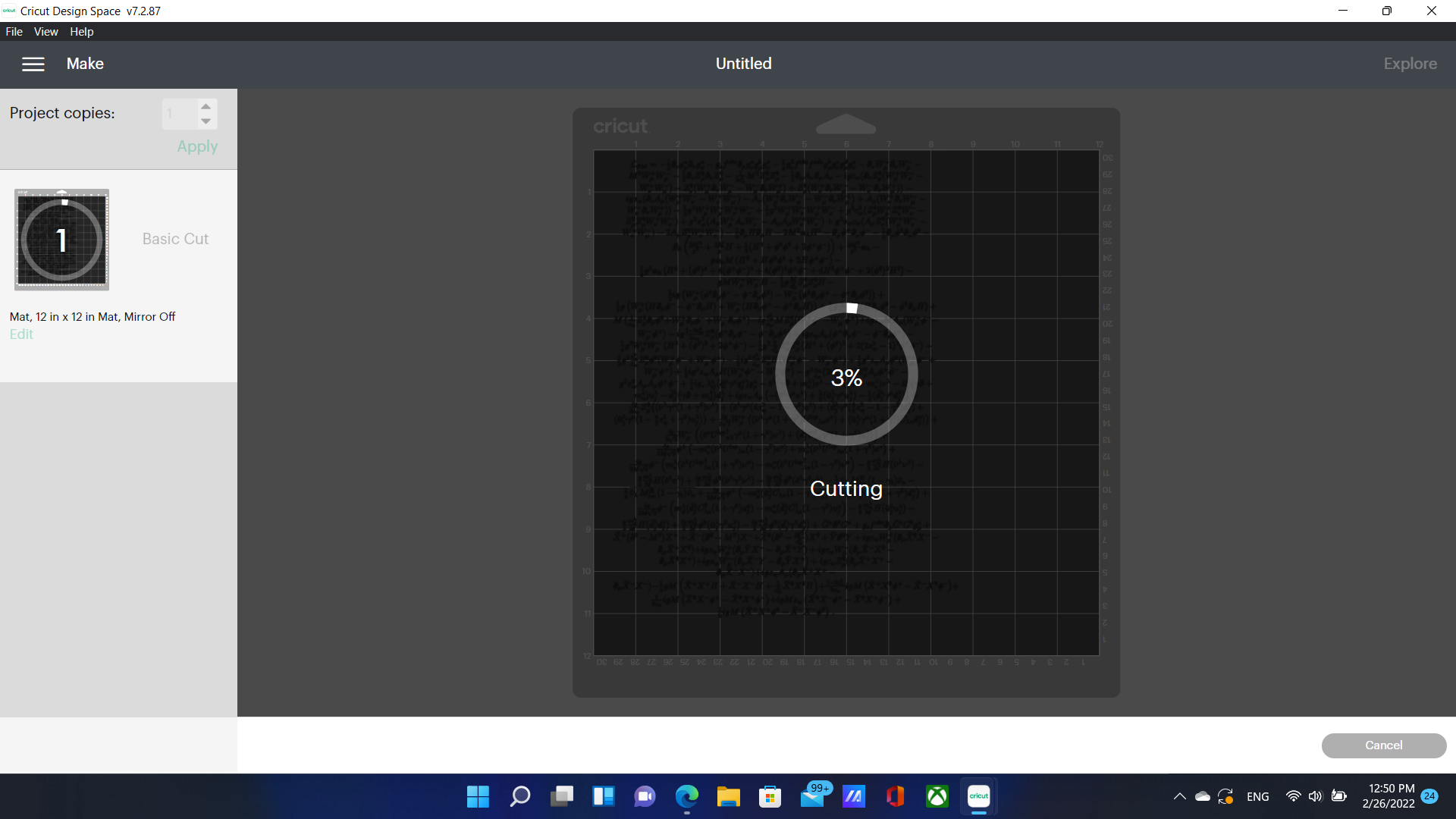
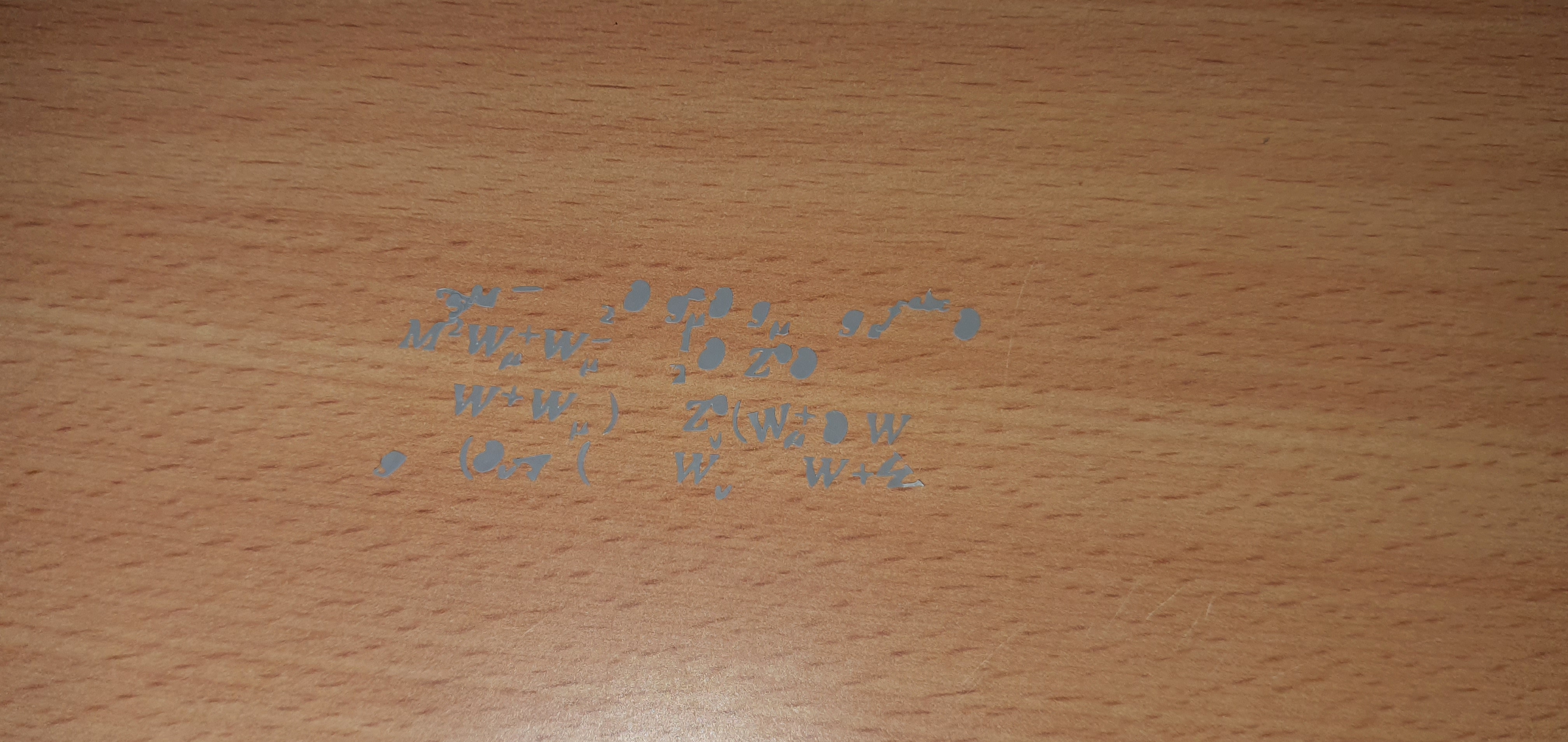
Unfortunately, The process was going to take too long and the cuts did not turn as smooth as I expected. This is why I chose only a small part of that equation and stopped the process after 5-10 minutes. I ended up with this:
I could not properly separate the desired parts from the unwanted parts but I tried and decided to make use of both parts. I attached the symbols to my table and the remaining part to my window.
Assignments
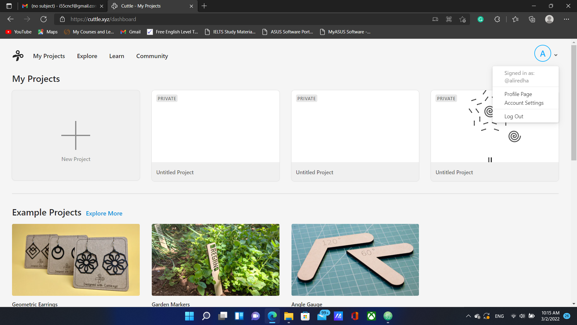
We were asked to make a design for laser cutting and cut the parts using the laser cutter by ourselves. I did not have Fusion 360 or autoCAD so I decided to work on cuttle.xyz which is an online software.
I started by thinking of a shape to assemble and decided at first to try building a DNA molecule.
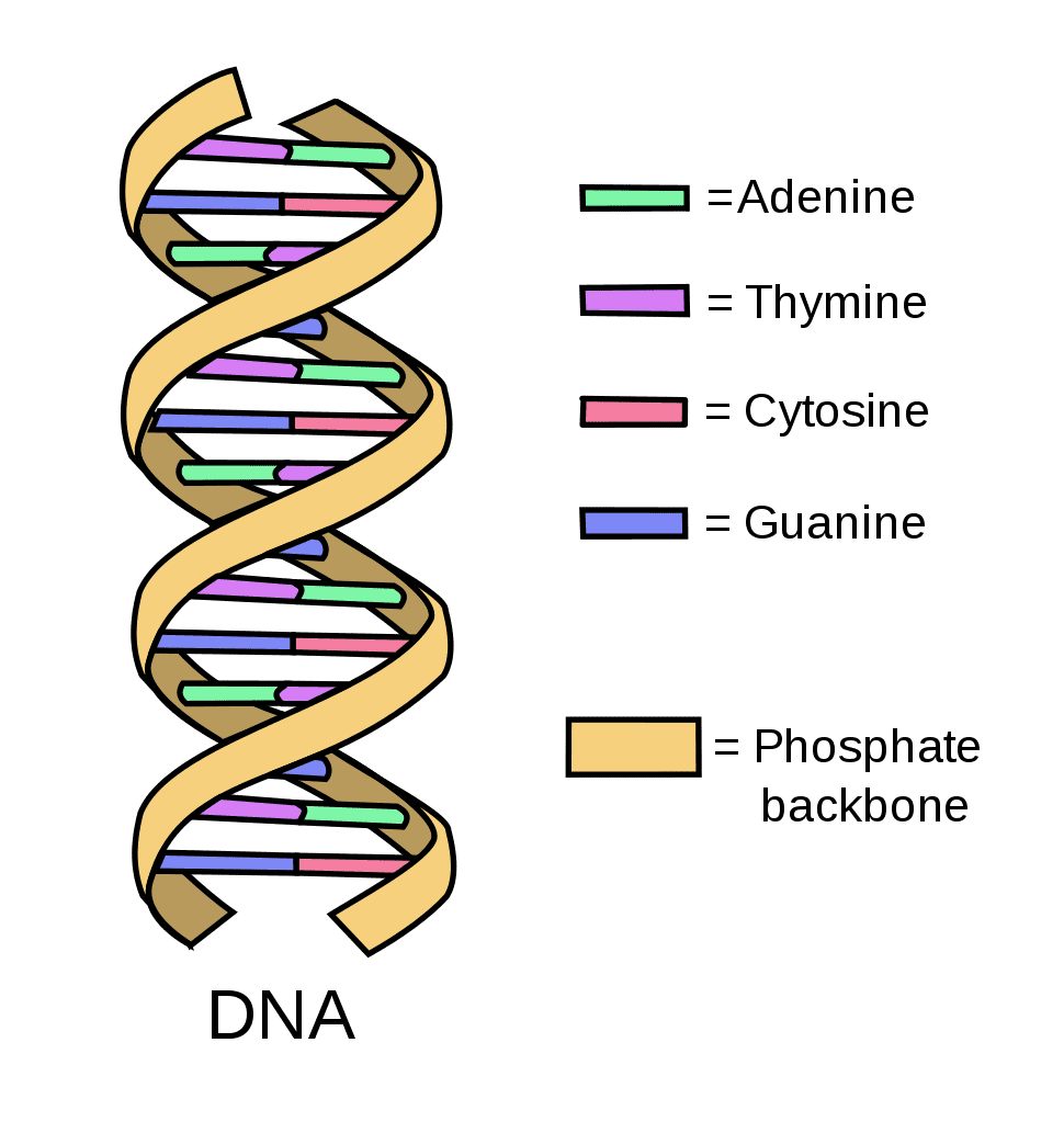
So I started with selecting two spiral shapes for the strands and chose a rectangle with cuts on both ends to be attached between the strands and represent a base pair.
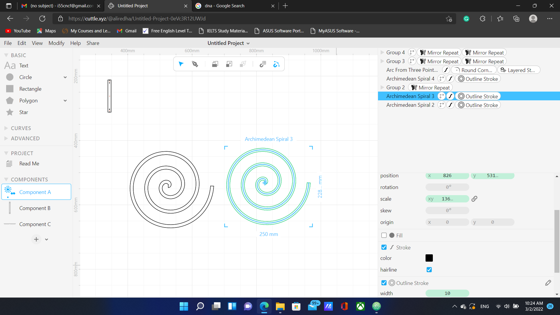
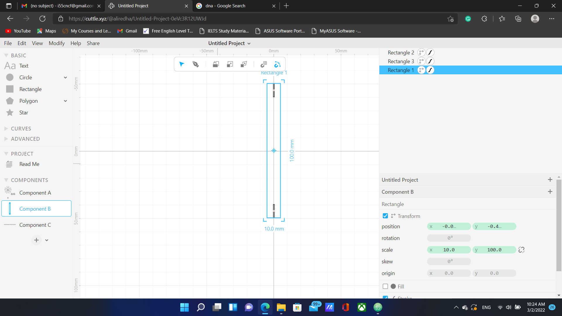
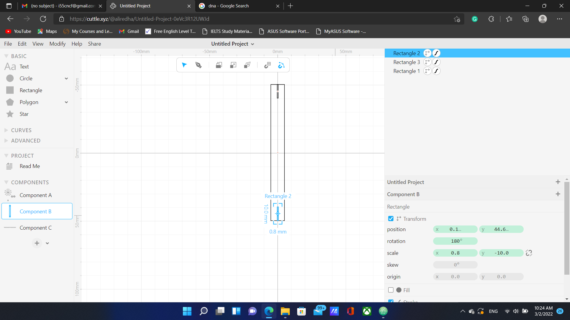
The settings are parametric which means that changing the dimensions of a certain component will automatically apply to all duplicated versions of that component and to the main component.
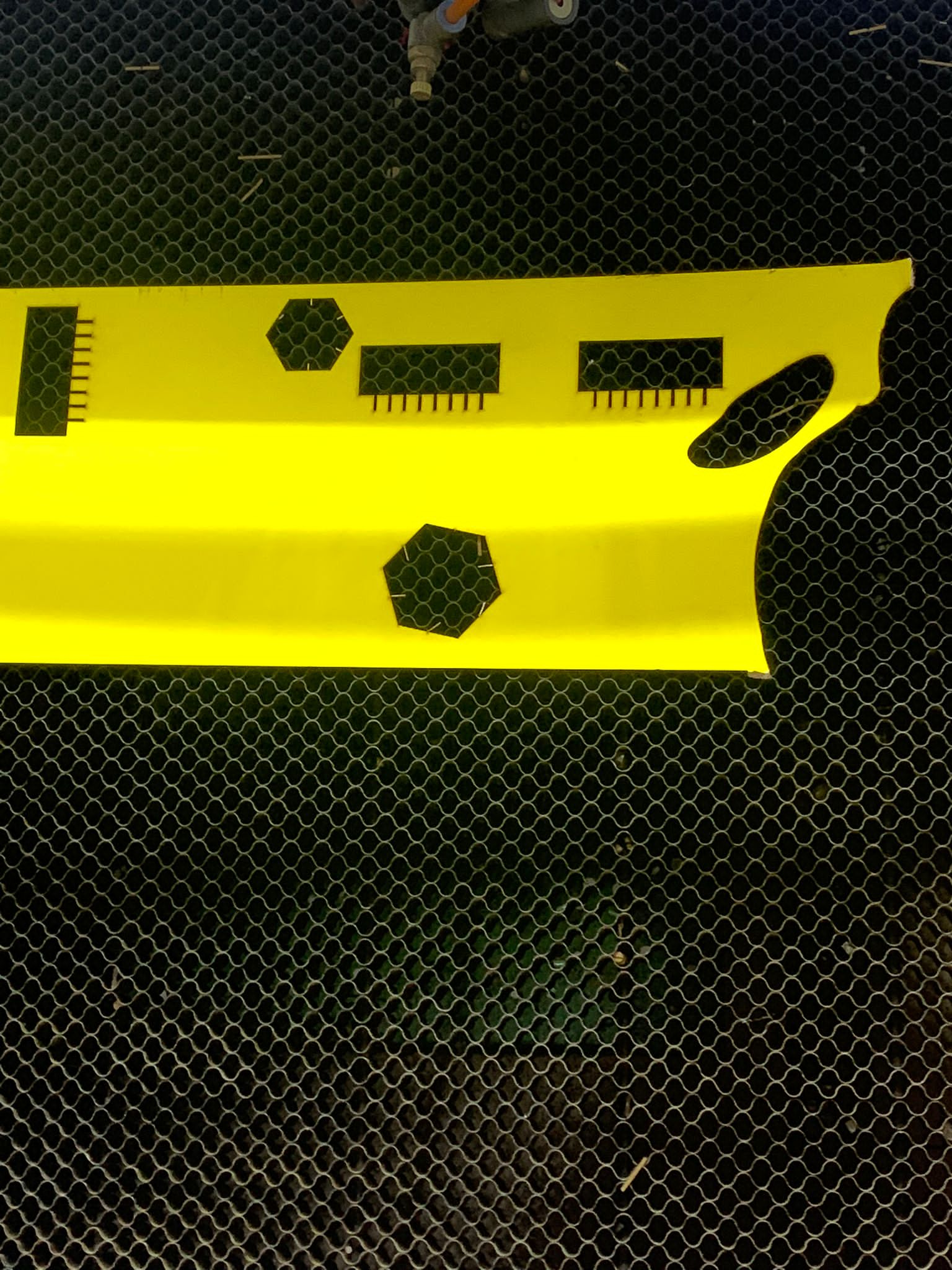
Once I was done with the design, I exported the DXF file that you can download from here and sent it to fablabbh.share@gmail.com in order to open my dxf file in the RDworks software. Once I view the file, I selected the square (base) and duplicated it to 40 other squares in 4 rows of 10 squares:
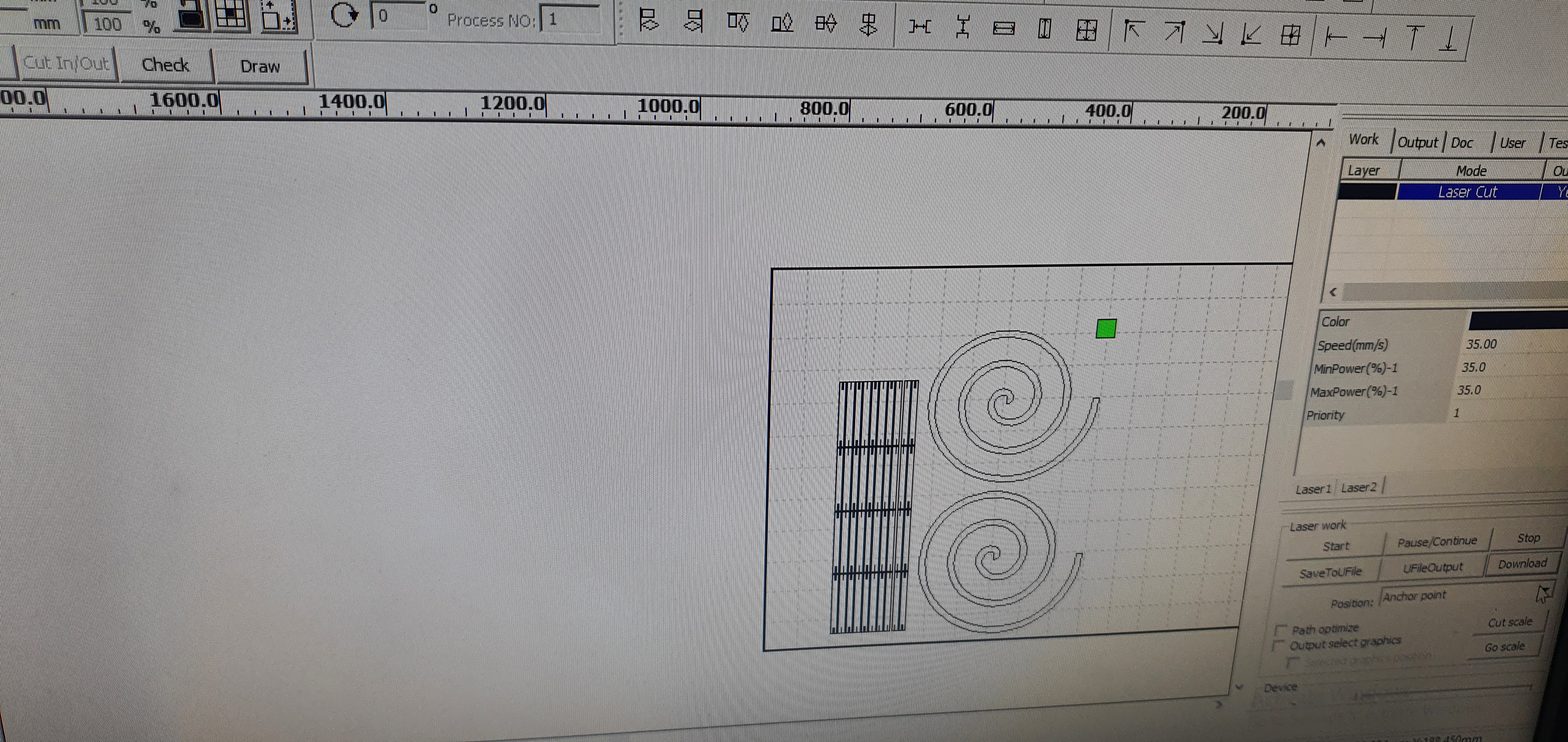
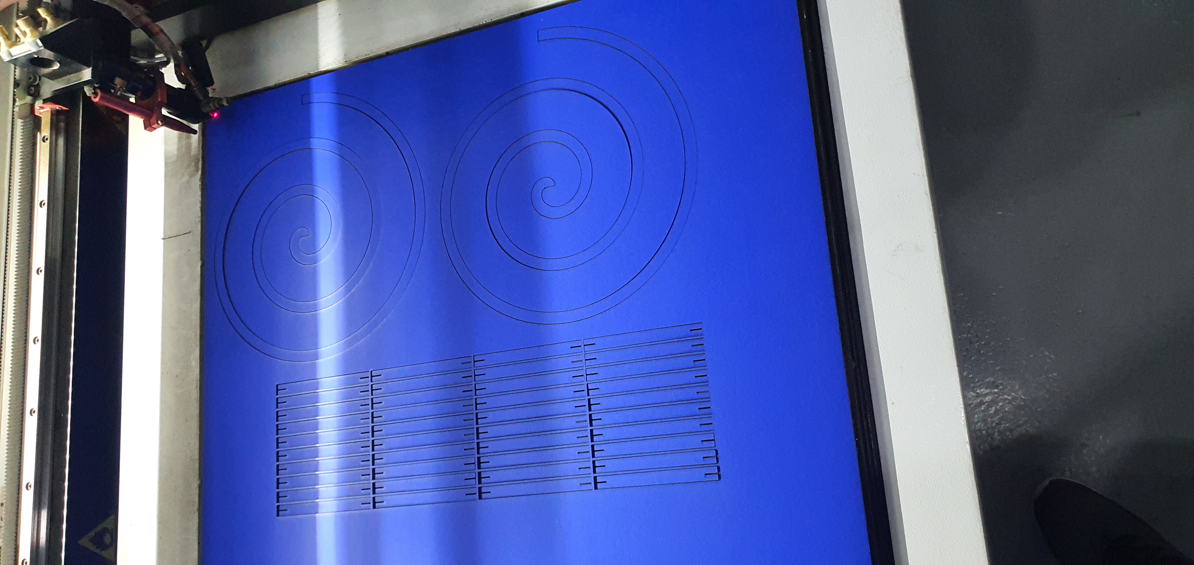
I fixed the position of squares and the spirals, pressed DOWNLOAD and then followed the steps to cut my design.
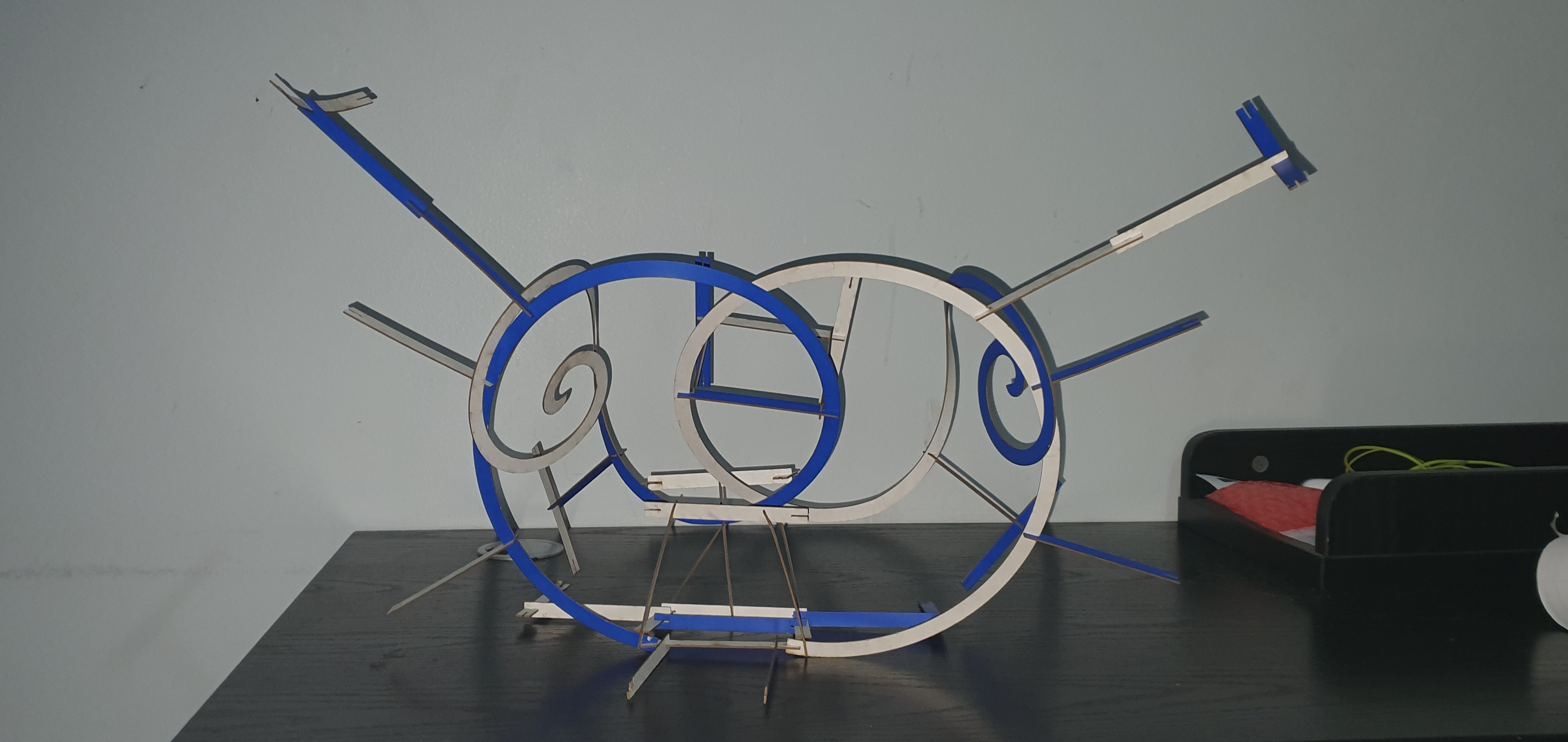
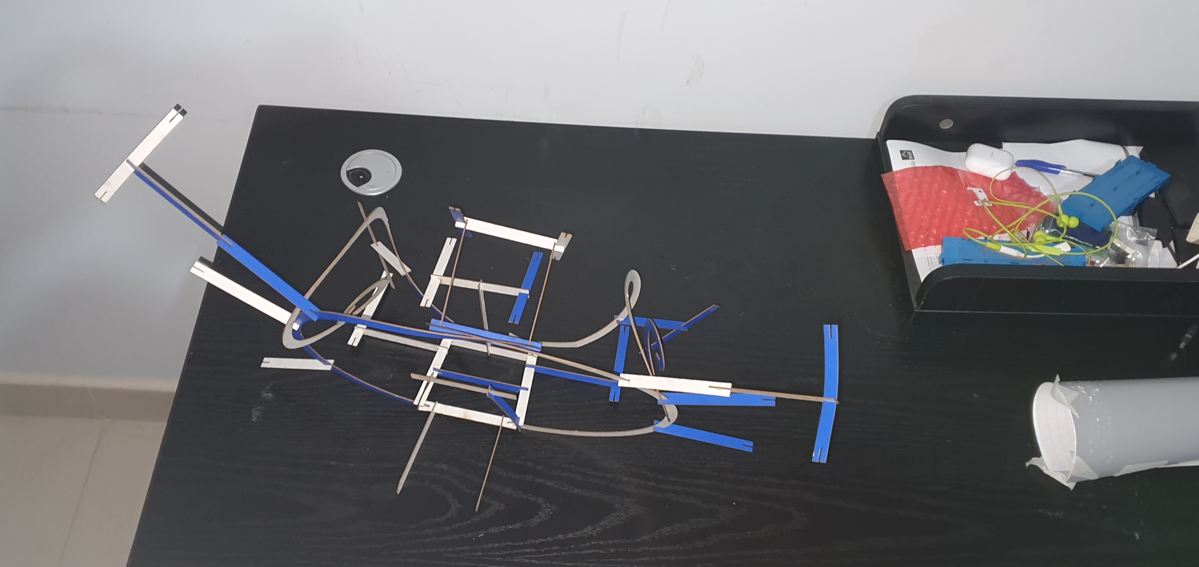
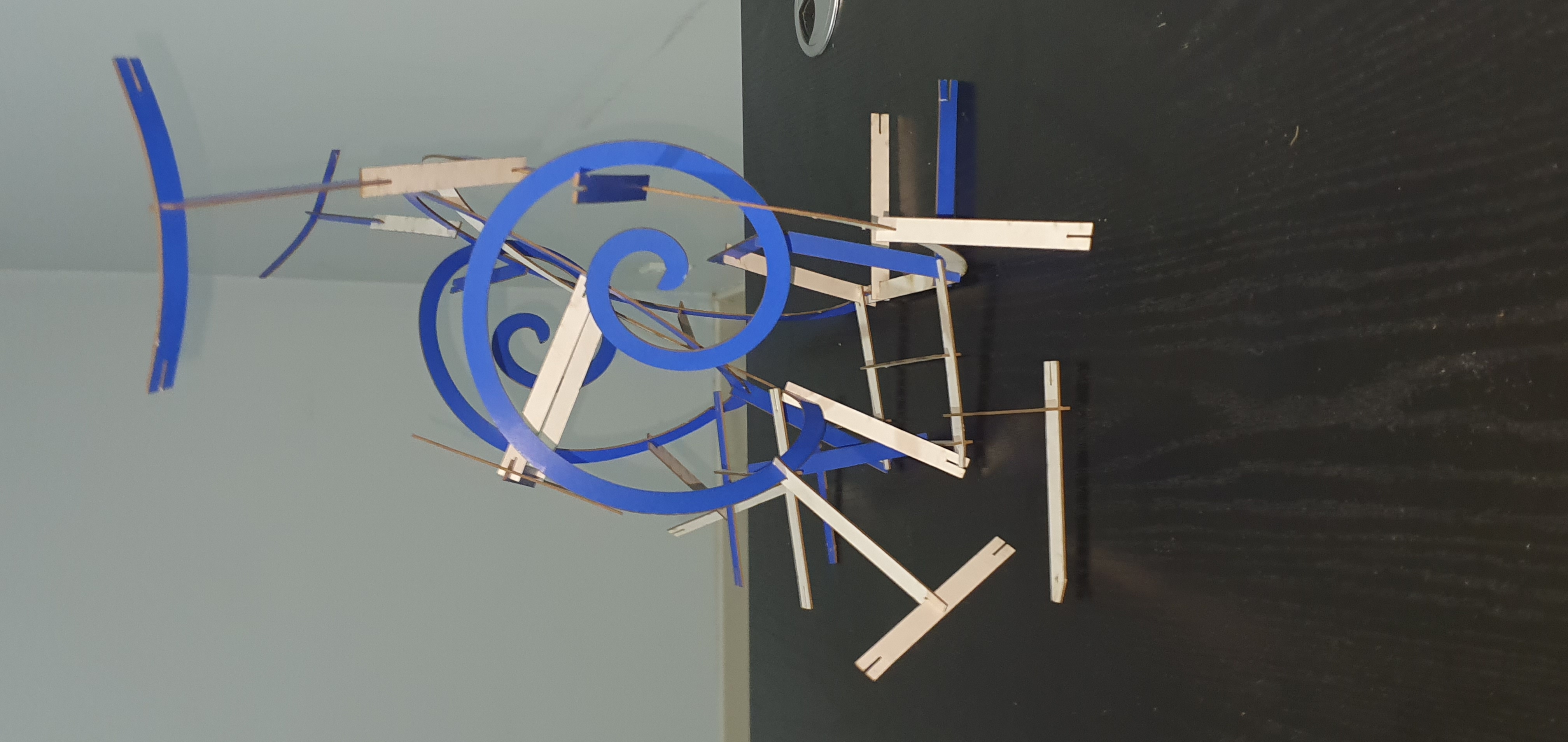
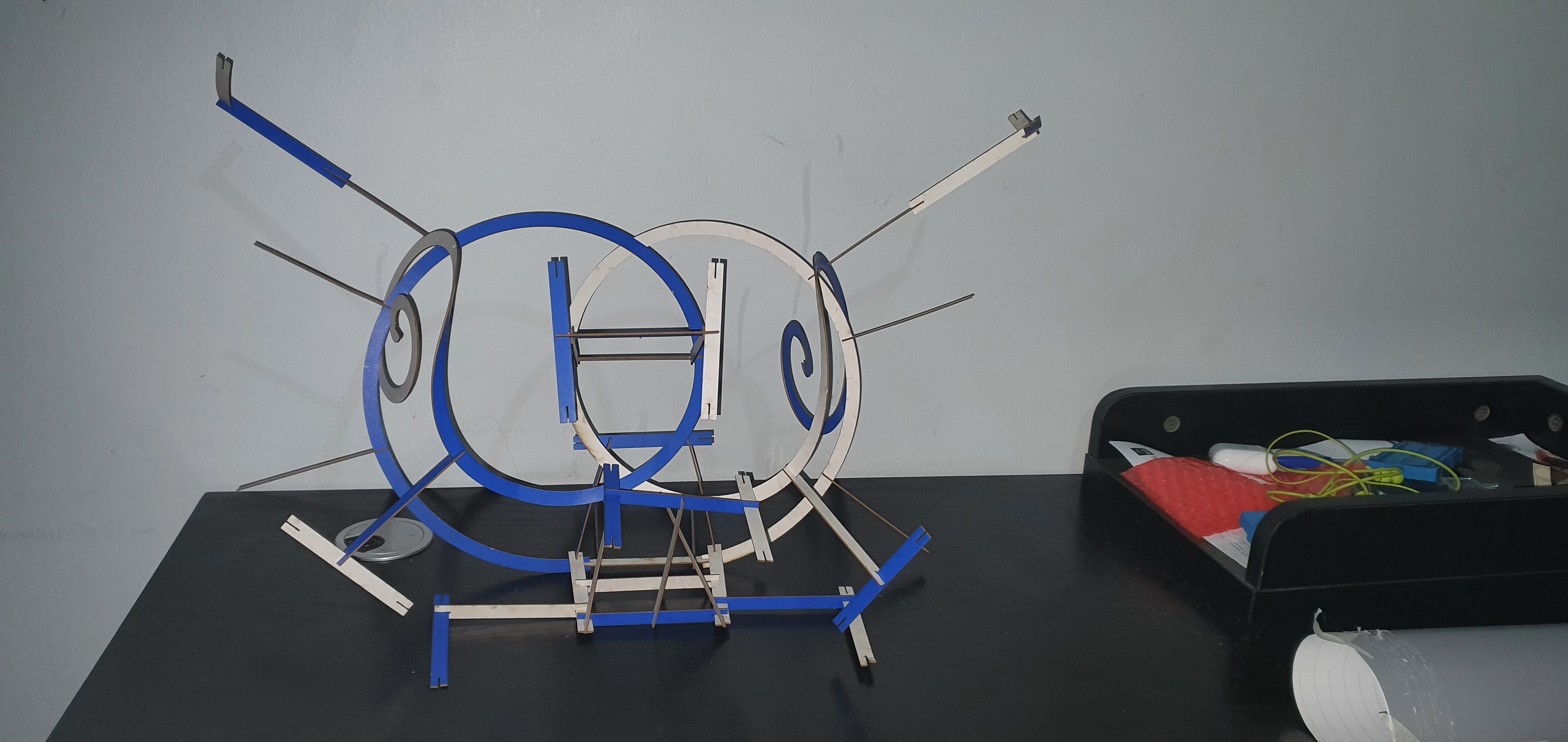
After the cutting process was finished, I picked up the parts and noticed that I cannot assemble a DNA molecule without causing noticeable deformities to the material.
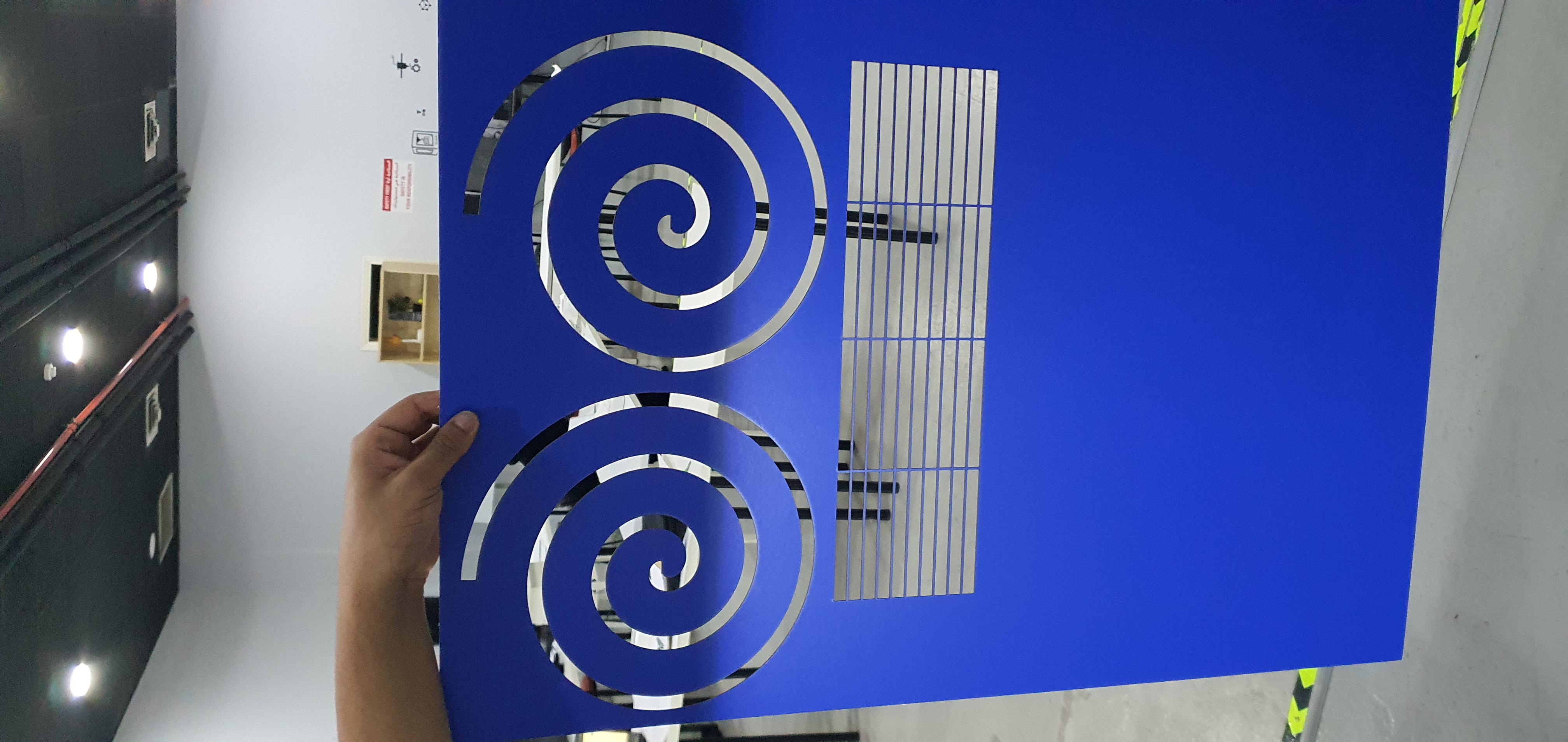
I had to change my design and use the parts to assemble something that is worth the cutting process. I decided to randomly place the parts together and this is what I came up with: