4. EMBEDDED PROGRAMMING

Background
General
Embedded Programming is a method used to program small micro-computers that carry out specific functions in some devices. Embedded programming is an essential part of software designing. Unlike OS-programming, Embedded programmers need to take into account the limitations of devices and microcontrollers.
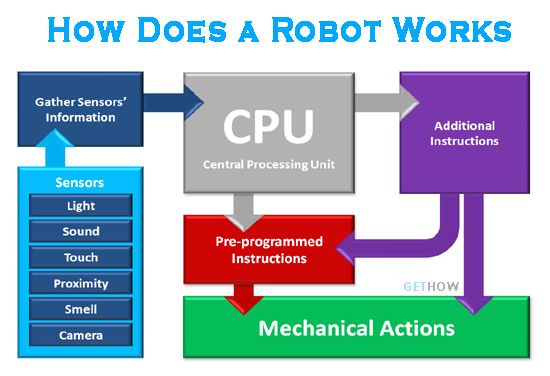
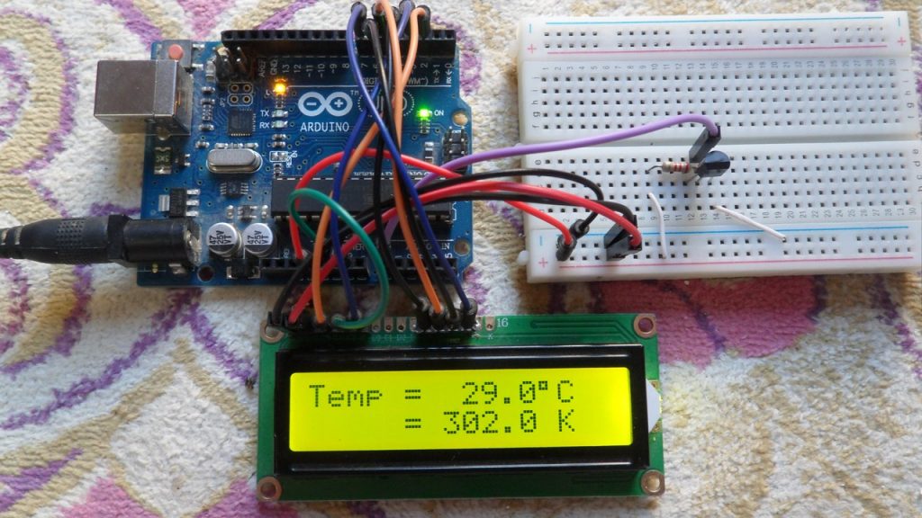
Embedded Programming involves assembling an electronic circuit that can perform specific functions and programming the circuit by coding in a specific programming language in a specific Integrated Development Environment and then transferring the code to the circuit. The electronic components within the circuit are controlled by the microcontroller which is considered to be the Central Processing Unit (CPU). When a series of commands are transferred to the microcontroller, the microcontroller gets programmed accordingly and causes the components to work together to perform desired tasks within the circuit. Together, the microcontroller and the electronic components form what is known as the Embedded System which interacts with the environment through Input/Output interfaces. The components can be classified to input and output devices. Input devices such as Ultrasonic sensors and microphones take data from the environment and convert it to digital data that can be processed by the microcontroller. Output devices such as speakers and LCD screens on the other hand, take processed digital data sent by the microcontroller in the form of electrical signals and convert them into a physical form such as sound or a displayed message.
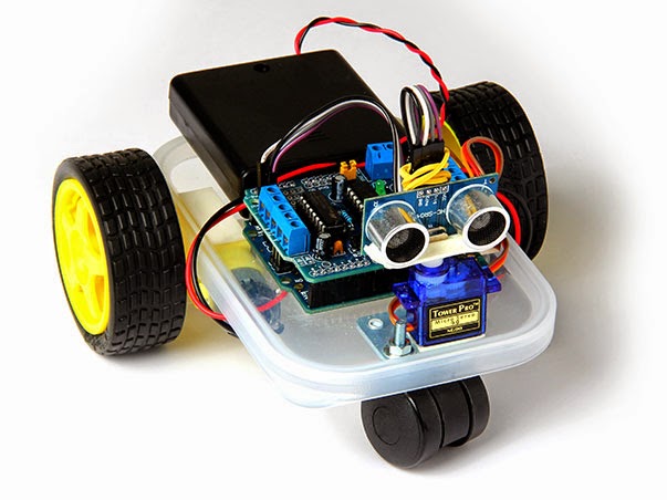
The applications of embedded programming range from small sensory devices to gaming consoles and to complex robotics.
Languages Used For Embedded Programming
There are many programming languages that can be used for embedded programming. each with specific properties and compatibilities. The most commonly used language is C and most embedded systems are based on it. The second most commonly used language is C++ which can be considered as an easier and upgraded version of C. Other languages include C#, Python, CircuitPython, MicroPython, Java, JavaScript, Ada, Assembly, Swift, R, Go, PhP and finally, Rust.
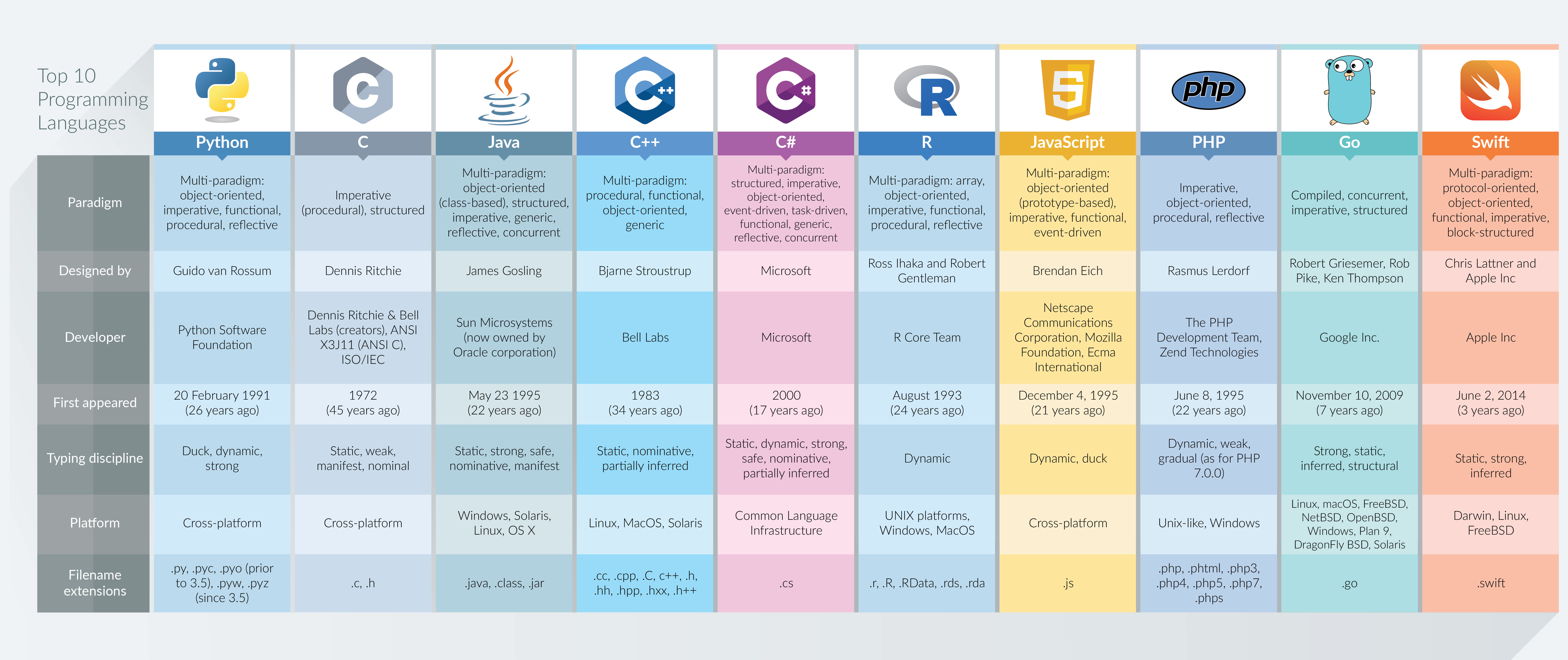
As a part of our group assignment, we were asked to compare between different embedded programming languages.
Microcontroller Boards (Development Boards)
Development boards are integrated circuits built to govern specific operations in embedded systems. Usually, microcontrollers consist of a CPU, RAM, Program memory, Oscillator and an A/D converter as shown below:
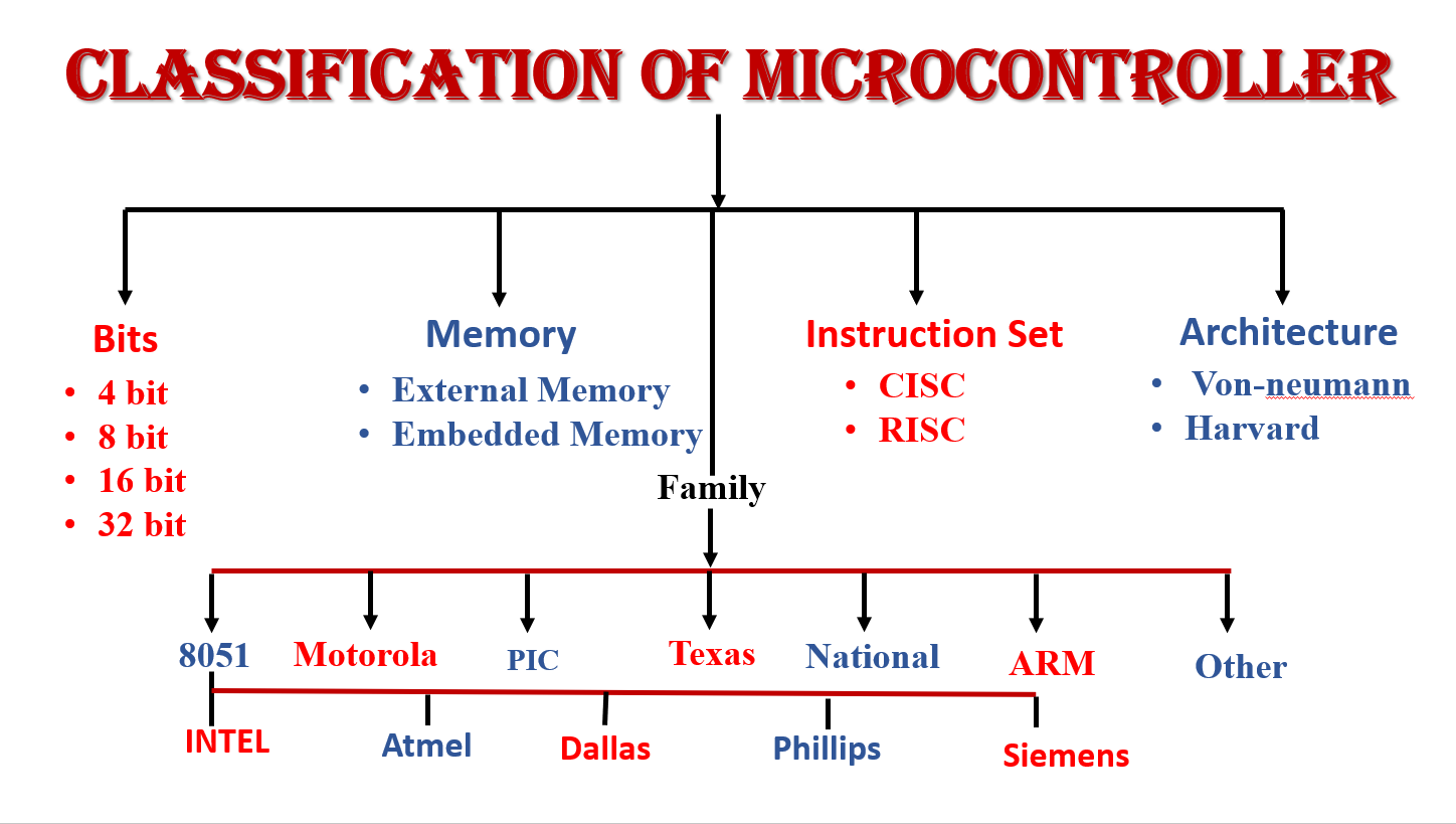
There are numerous types of Development boards that can be used to build and program sophisticated circuits. The image below shows the classification of microcontrollers based on Bits, Memory, Instruction Set, Architecture and family:
There are different brands of microcontroller boards such as Arduino Uno, Raspberry pi and Adafruit. The video below shows the comparison between different brands:
As a part of our group assignment, we were asked to compare between different development boards and define which languages can be used for each board type.
Development Environments
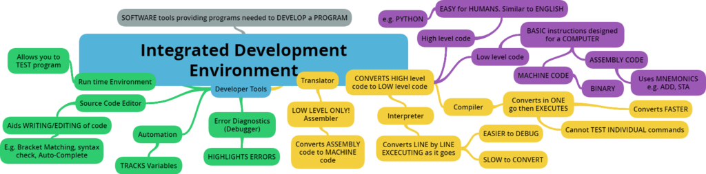
An integrated development environment is a software application that provides the necessary tools for programmers and software developers. An IDE consists of three major parts: code editor, build automation tools and a debugger.
There are multiple development environments for embedded programming such as Arduino IDE, Microsoft Visual Studio and labVIEW.
Datasheet
The datasheet contains information about the Adafruit feather nRF52840 express developing board.
Features
Power Pins
Analog Pins
Sensors
Setting Everything Up
Installation
I started this week with downloading the Arduino IDE and setting up the environment for embedded programming. I was given a small microcontroller called Adafruit feather nRF52840 sense and a connection wire.
These are the steps I have followed:
1- I downloaded the Arduino IDE
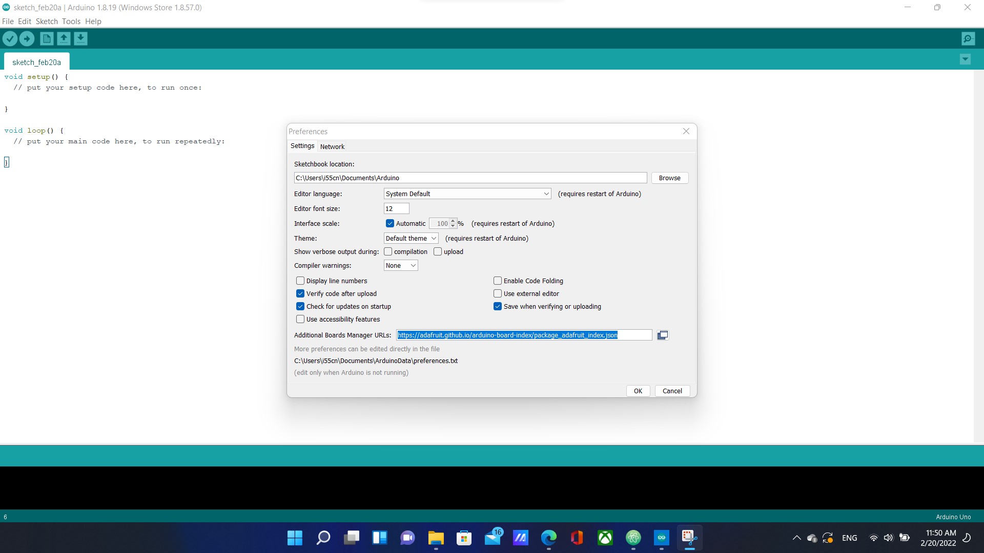
2- Copied a link and then navigated to File>Preferences> and pasted it in Additional Boards Manager URLs as shown below to access Adafruit libraries:
3- By navigating to Tools>Manage Libraries>, I searched for Adafruit nRF52 and installed it
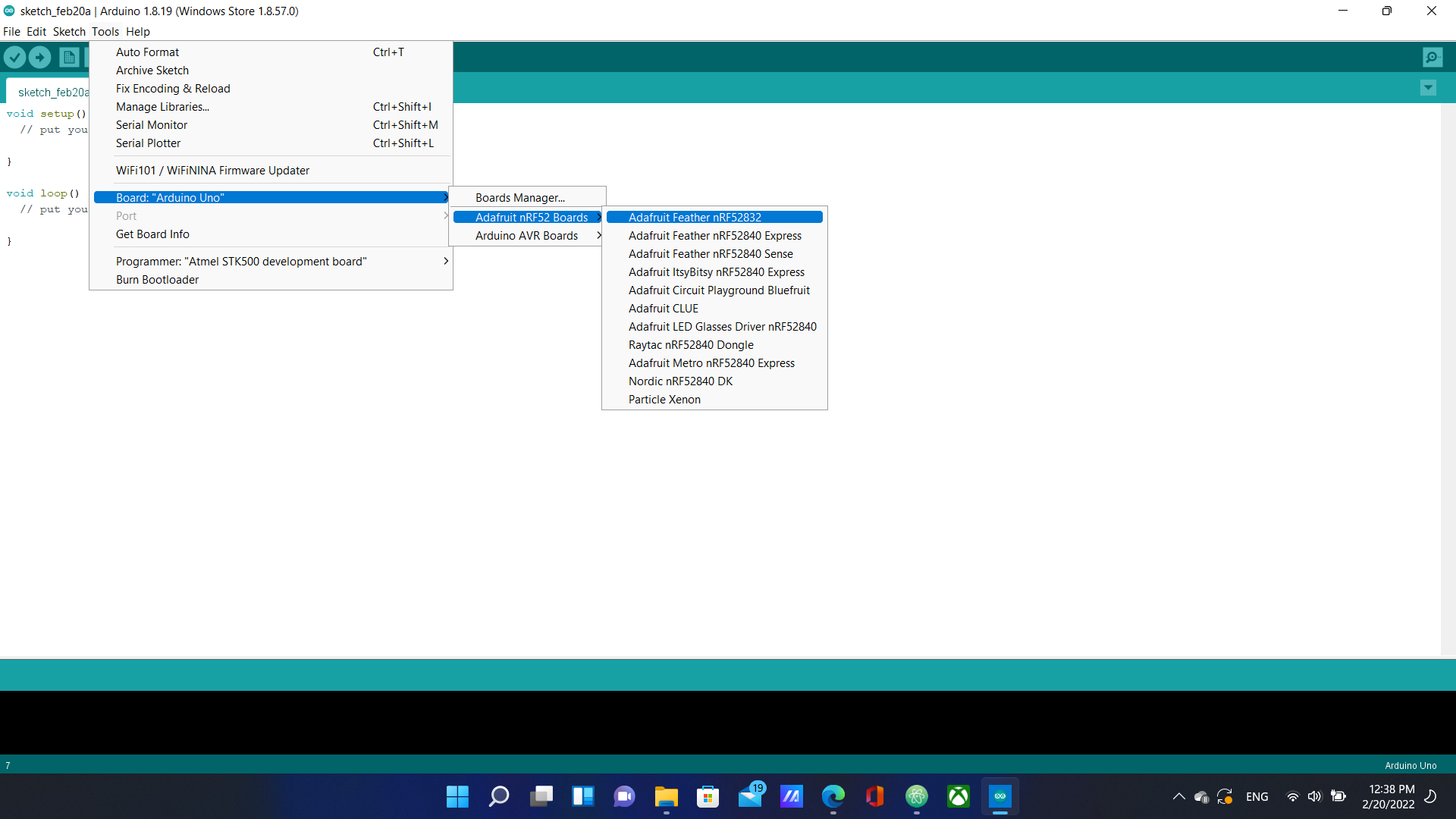
4- From Tools>Board:”Arduino Uno”>Adafruit nRF52 Boards, I selected Adafruit Feather nRF52840
5- I connected the board to my laptop, and double pressed the button next to the yellow LED
6- Finally, I connected the microcontroller to my laptop and it got recognized
Bootloader Update
I noticed that I kept getting an error message when trying to upload a sample sketch to my Adafruit. After looking online for a solution, I discovered that the Bootloader’s version was old. I found three ways to update the Bootloader and I chose the simplist way to do so. I downloaded a new UF2 file from the Adafruit website and then dragged it to FTHR840BOOT which is the device name for the Adafruit board.
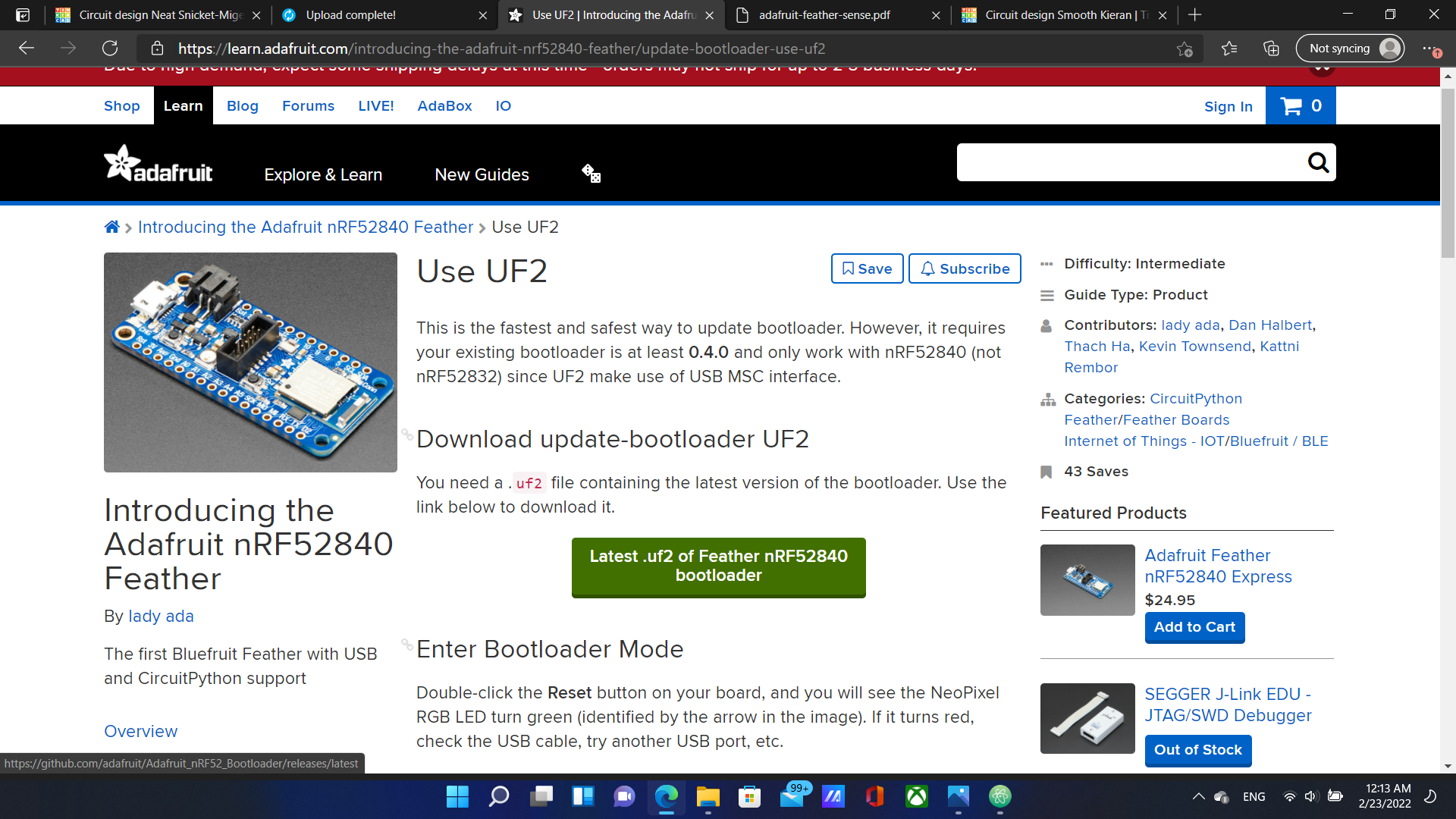
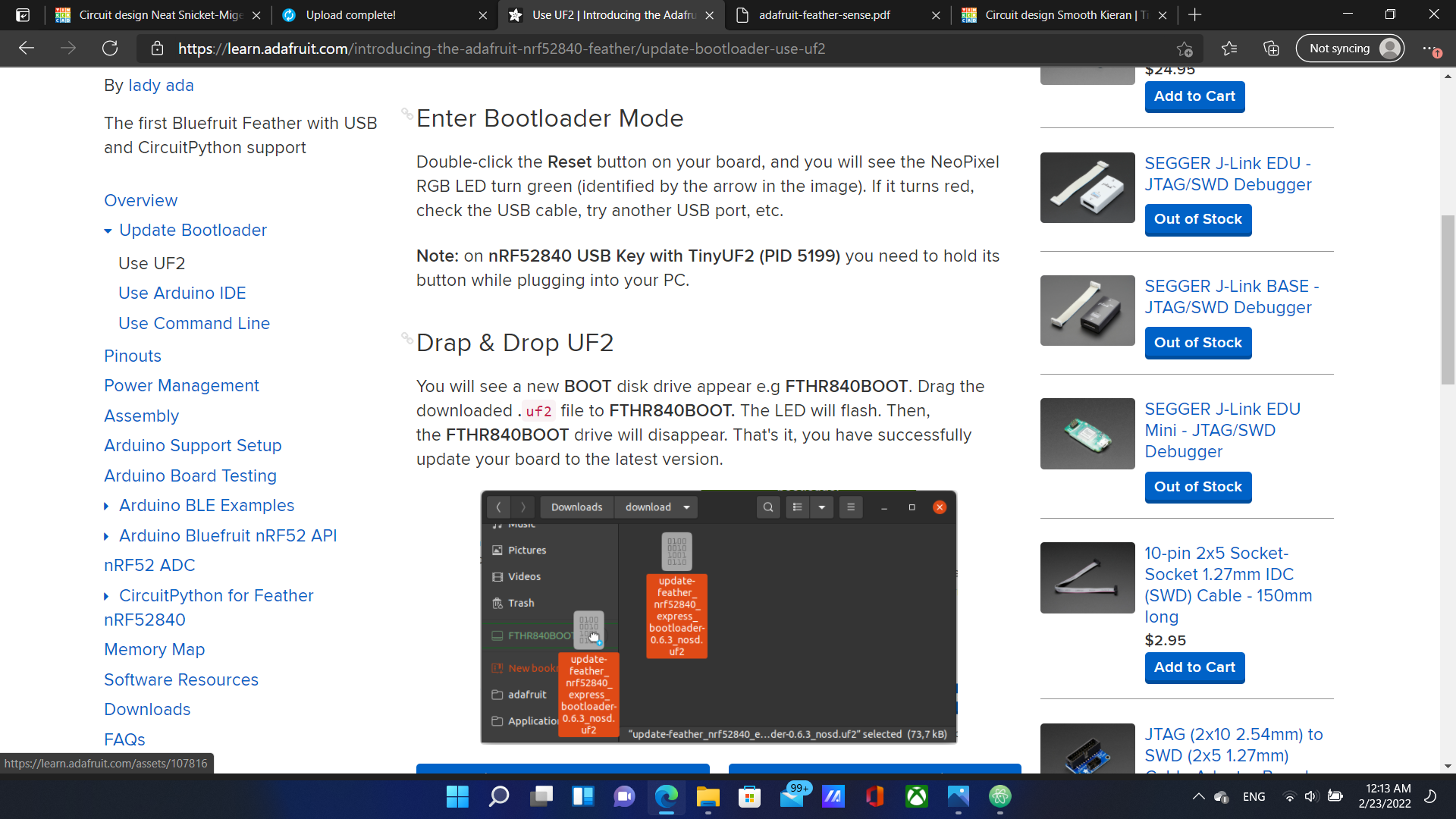
After carefully following the steps in the website, The Bootloader was successfully updated.
Starting With Examples
I began with searching for example codes.
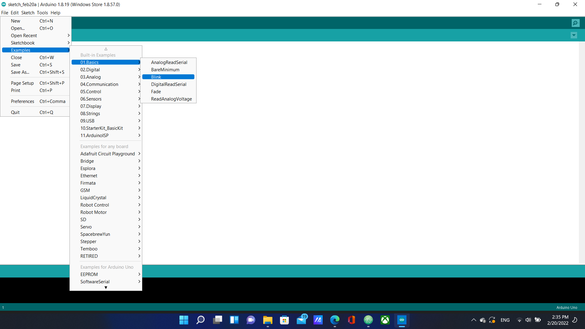
I chose “Blink” because it was the most basic and pressed the upload button to upload it to the microcontroller. The picture bellow shows the code and the comments about what each line does.
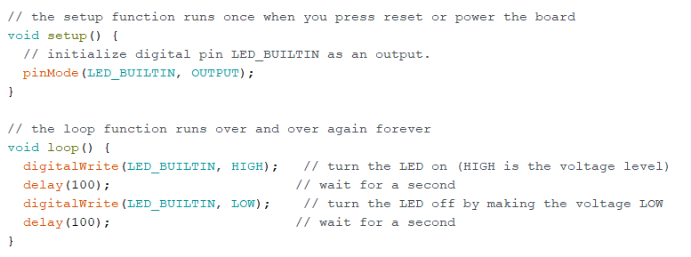
This code causes the red built-in LED light to turn on for a second and then off repeatedly. I changed the High and low delay times from 1000ms to 200ms as shown below:

Other Programming languages
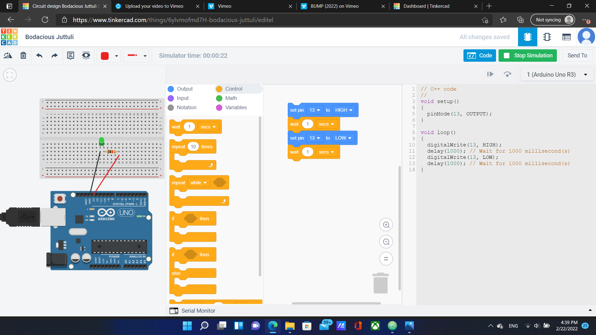
Next, I tried using other programming languages other than C++ which is used in the Arduino IDE. I built a simple circuit in TinkerCAD that causes the built in LED to blink. This time however, I used blocks instead of C++ and an Arduino Uno microcontroller instead of Adafruit as shown below:
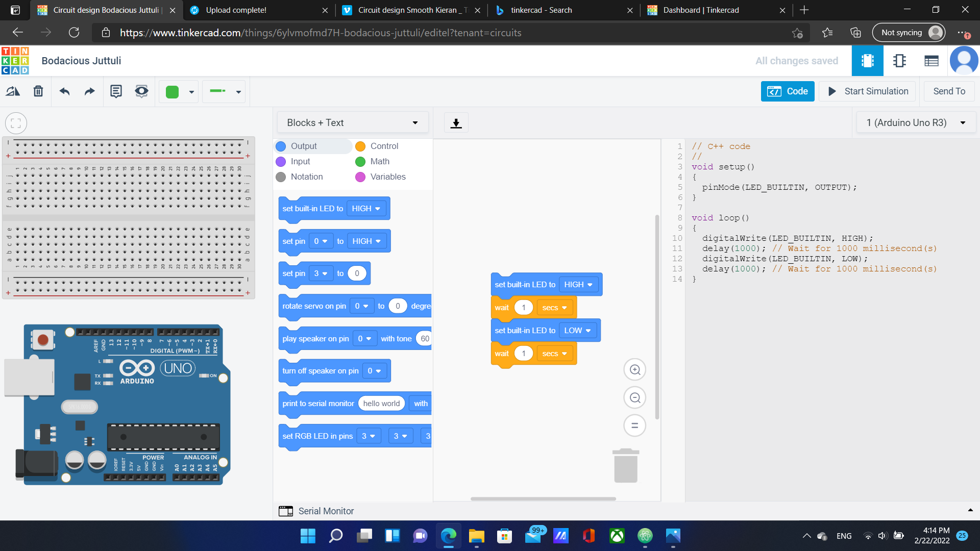
TinkerCAD converts Codeblocks to C++ automatically which makes it a great tool for beginners.
For fun, I added an external LED and made it blink.
You can follow this link to view and edit my circuit
Challenges
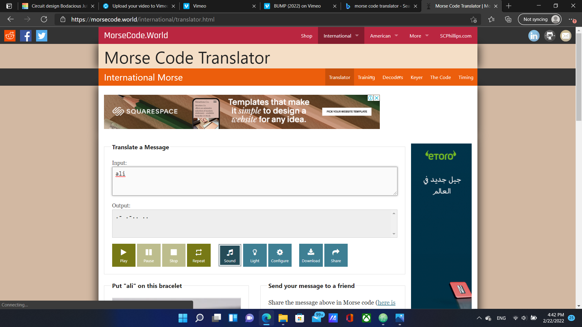
We were challenged to covert words of our choosing to morse code and then program our circuits to produce light signals that correspond to the morse code. I used a morse code translator to convert my name “Ali” to dots and dashes as shown below:
Morse Code Rules
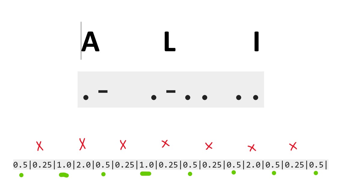
- The dots represent 0.5 seconds of being on, while the dashes 1 second of being on.
- Between each two elements within the same letter, there is an off period of 0.25 seconds
- Between letters, there is a 2 seconds off period
To make things easier, I decided to assign a time period to each part of the morse code according to the rules listed above as shown below:
After that, I started assembelling the circuit and Building the Blocks for the code as shown in the video below:
Finally, I started the simulation:
Assignments
I sent my design to a colleague and challenged her to decipher it. After many trials, she succeeded and sent me her design so I could decipher it as well. I started by noticing the duration of the blinks and interpreting the time durations into dots and dashes.
After that, I looked up the Morse code alphabet and linked the dots and dashes to their letter equivalents.
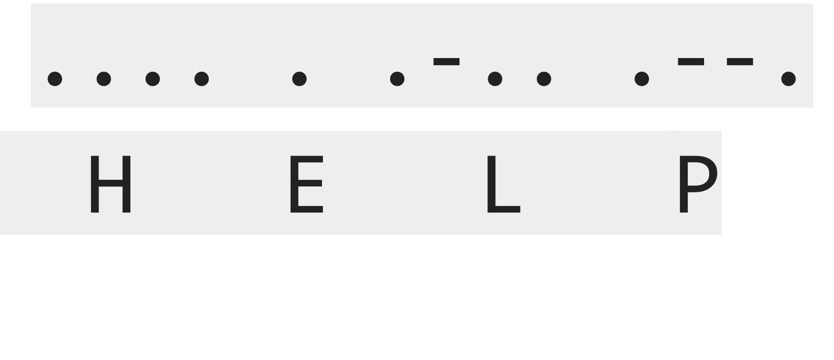
I found the secret message to be HELP.
Useful links
- steps
- Arduino IDE
- datasheet
- Adafruit website
- Blink
- TinkerCAD
- morse code translator
- Jekyll
- Markdown
Code Example
// C++ code for morse light signal

void setup()
{
  pinMode(13, OUTPUT);
}

void loop()
{
  digitalWrite(13, HIGH);
  delay(500); // Wait for 500 millisecond(s)
  digitalWrite(13, LOW);
  delay(250); // Wait for 250 millisecond(s)
  digitalWrite(13, HIGH);
  delay(1000); // Wait for 1000 millisecond(s)
  digitalWrite(13, LOW);
  delay(2000); // Wait for 2000 millisecond(s)
  digitalWrite(13, HIGH);
  delay(500); // Wait for 500 millisecond(s)
  digitalWrite(13, LOW);
  delay(250); // Wait for 250 millisecond(s)
  digitalWrite(13, HIGH);
  delay(1000); // Wait for 1000 millisecond(s)
  digitalWrite(13, LOW);
  delay(250); // Wait for 250 millisecond(s)
  digitalWrite(13, HIGH);
  delay(500); // Wait for 500 millisecond(s)
  digitalWrite(13, LOW);
  delay(250); // Wait for 250 millisecond(s)
  digitalWrite(13, HIGH);
  delay(500); // Wait for 500 millisecond(s)
  digitalWrite(13, LOW);
  delay(2000); // Wait for 2000 millisecond(s)
  digitalWrite(13, HIGH);
  delay(500); // Wait for 500 millisecond(s)
  digitalWrite(13, LOW);
  delay(250); // Wait for 250 millisecond(s)
  digitalWrite(13, HIGH);
  delay(500); // Wait for 500 millisecond(s)
  digitalWrite(13, LOW);
  delay(20000); // Wait for 20000 millisecond(s)
}