7. INPUT AND OUTPUT DEVICES
This week, I was introduced to input and output devices. I became familiar with how to set the electrical components that we have as either output or input.
ASSIGNMENTS
Input
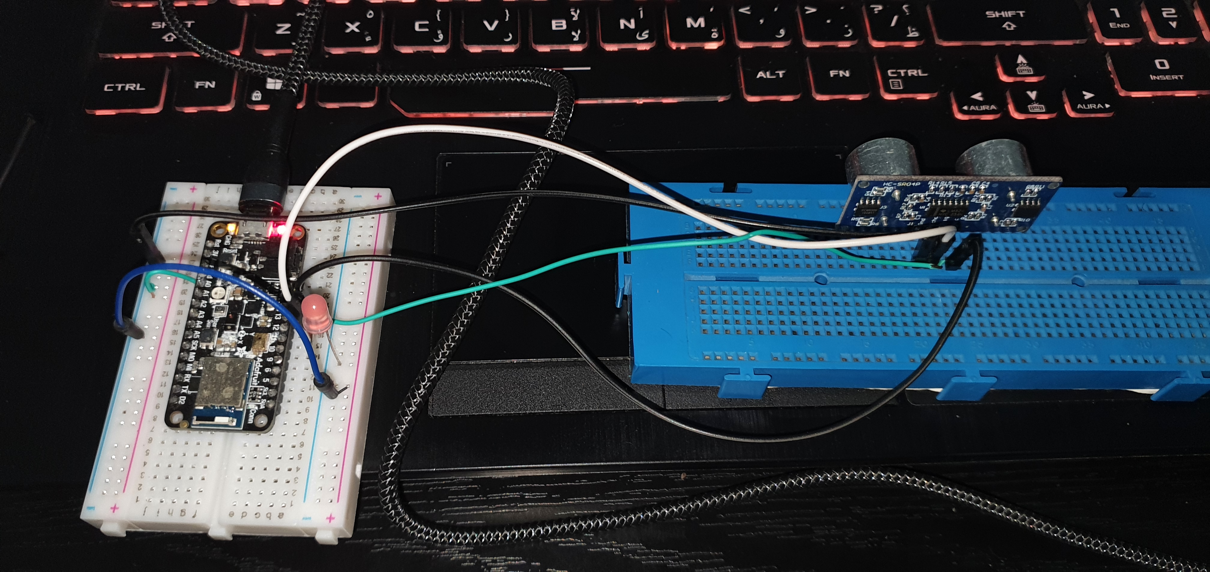
For this week, we had to pick a sensor and use it to measure something and display the measurement either on serial monitor or an output lcd. I started by picking an ultrasonic sensor and using it to measure distance. I started assembling the circuit as shown below:
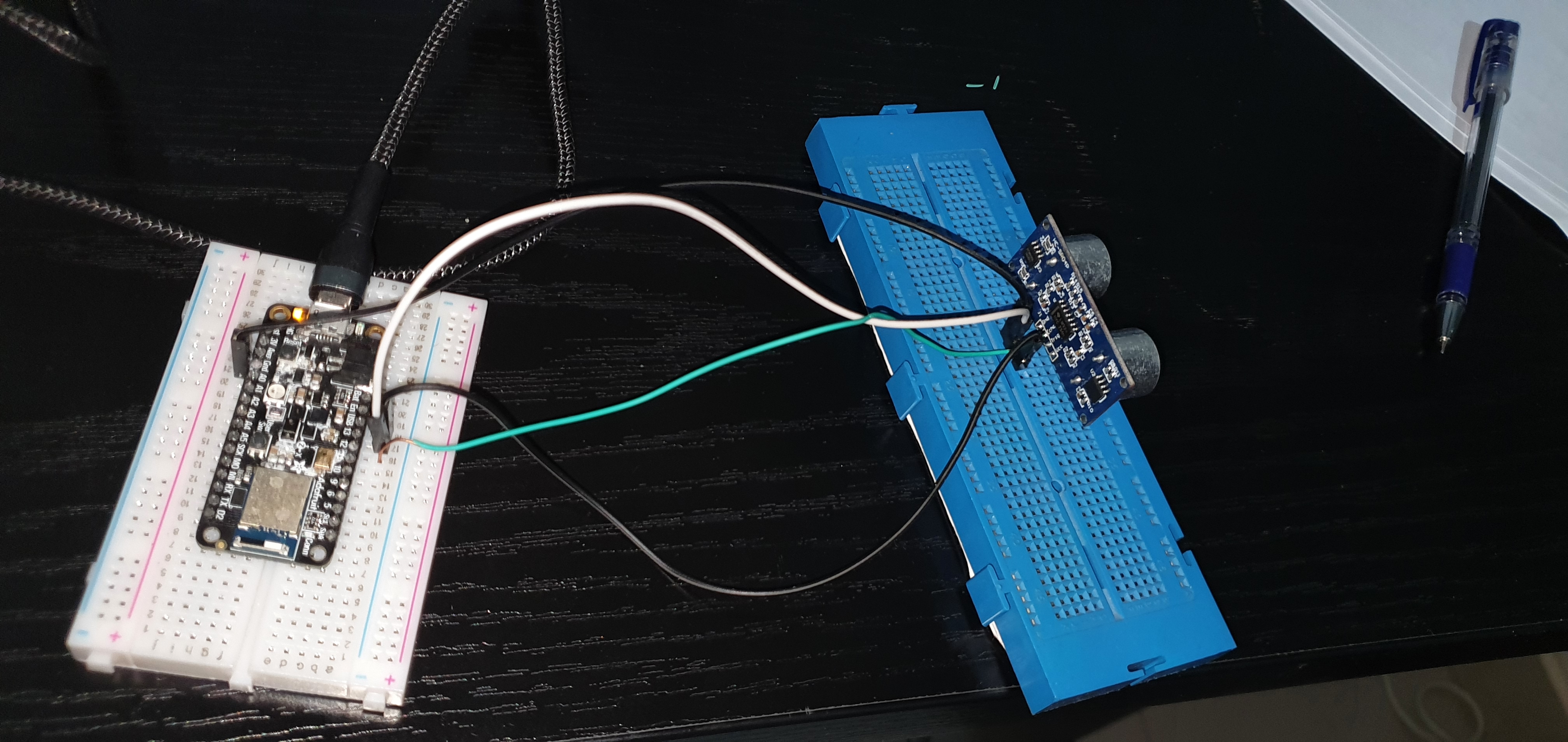
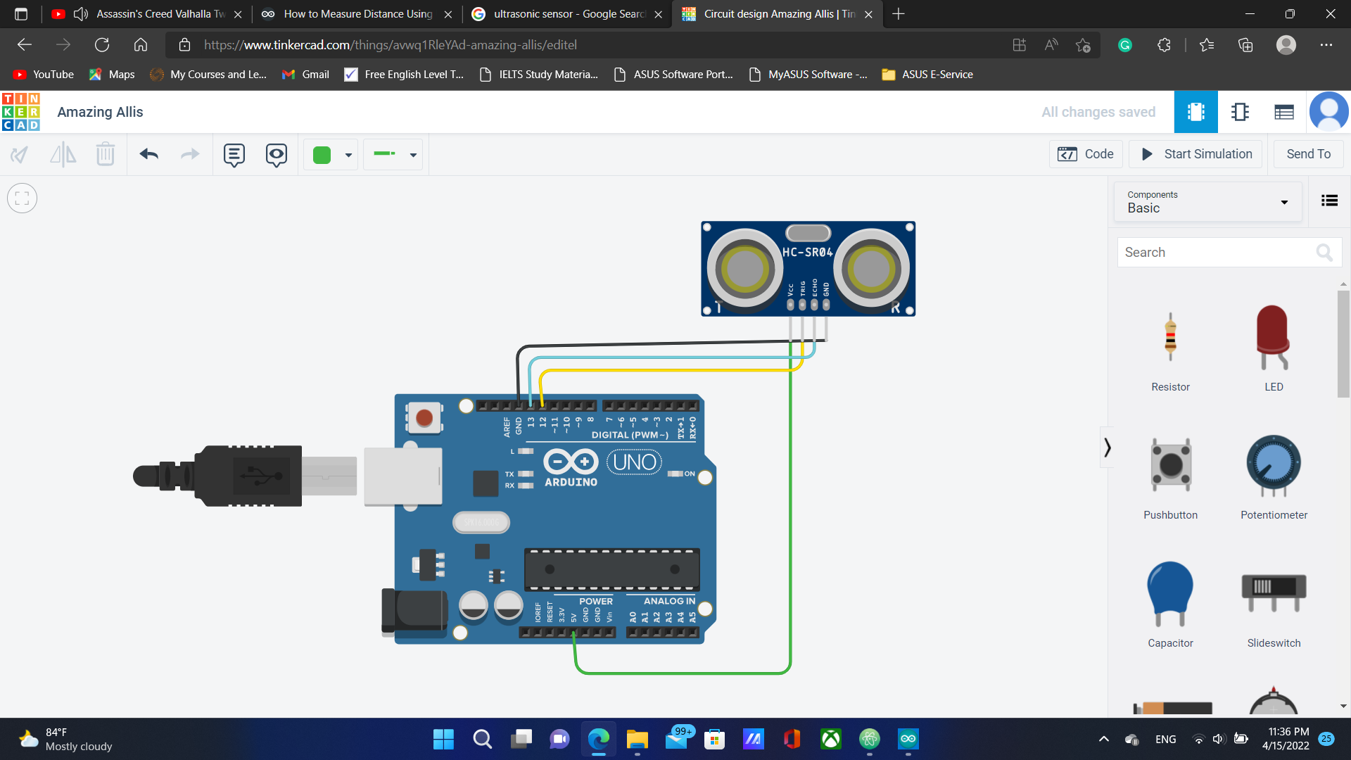
I connected the VCC pin of the sensor to the USB pin on the adafruit because it can supply 4.3-5.3 V, pin trig to pin number 12, echo to pin number 13, and ground pin to GND. the picture below shows the circuit as done using TinkerCAD:
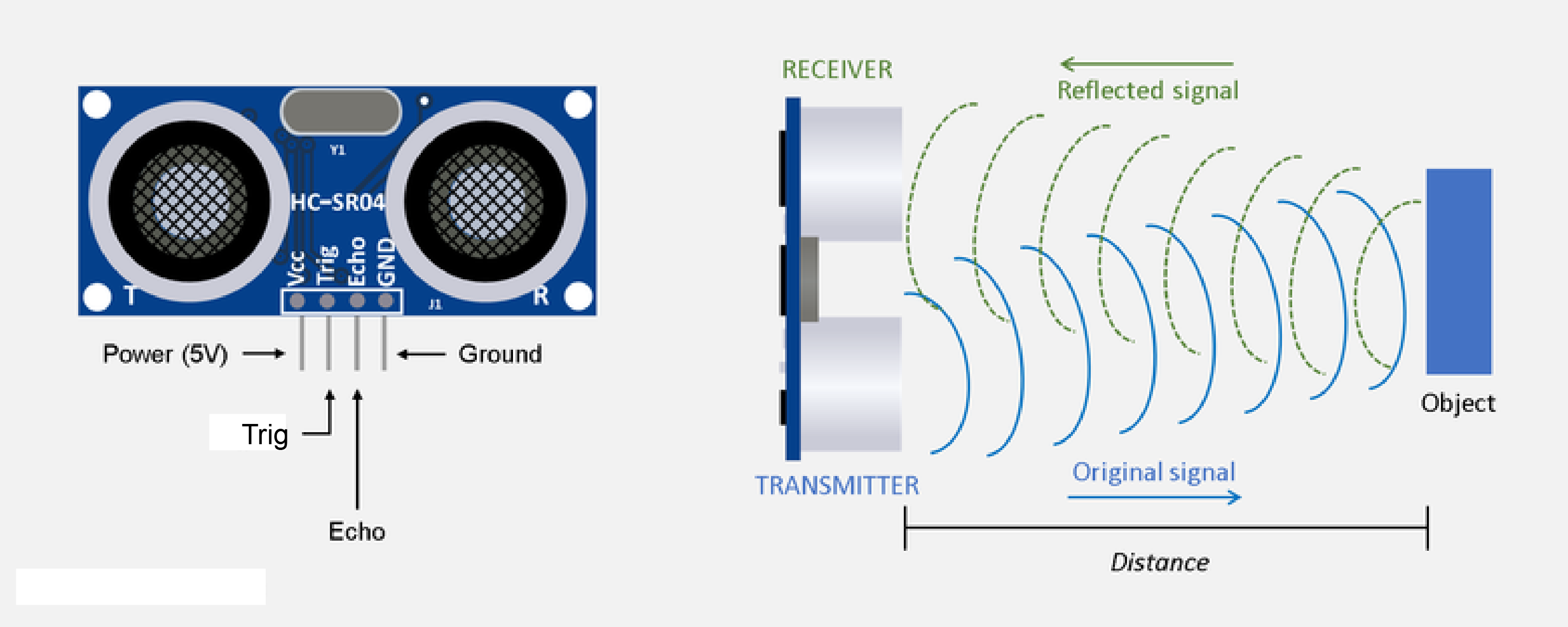
when the trig pin is set to high, an electrical signal is sent to the transmitter on the sensor and causes it to vibrate and send ultrasonic waves. As these waves bounce off objects and reflect back, the receiver detects these waves and converts them into electrical signals that are sent through the echo pin to the microcontroller which processes them and can store them as data to use them to perform necessary calculations to measure distance.
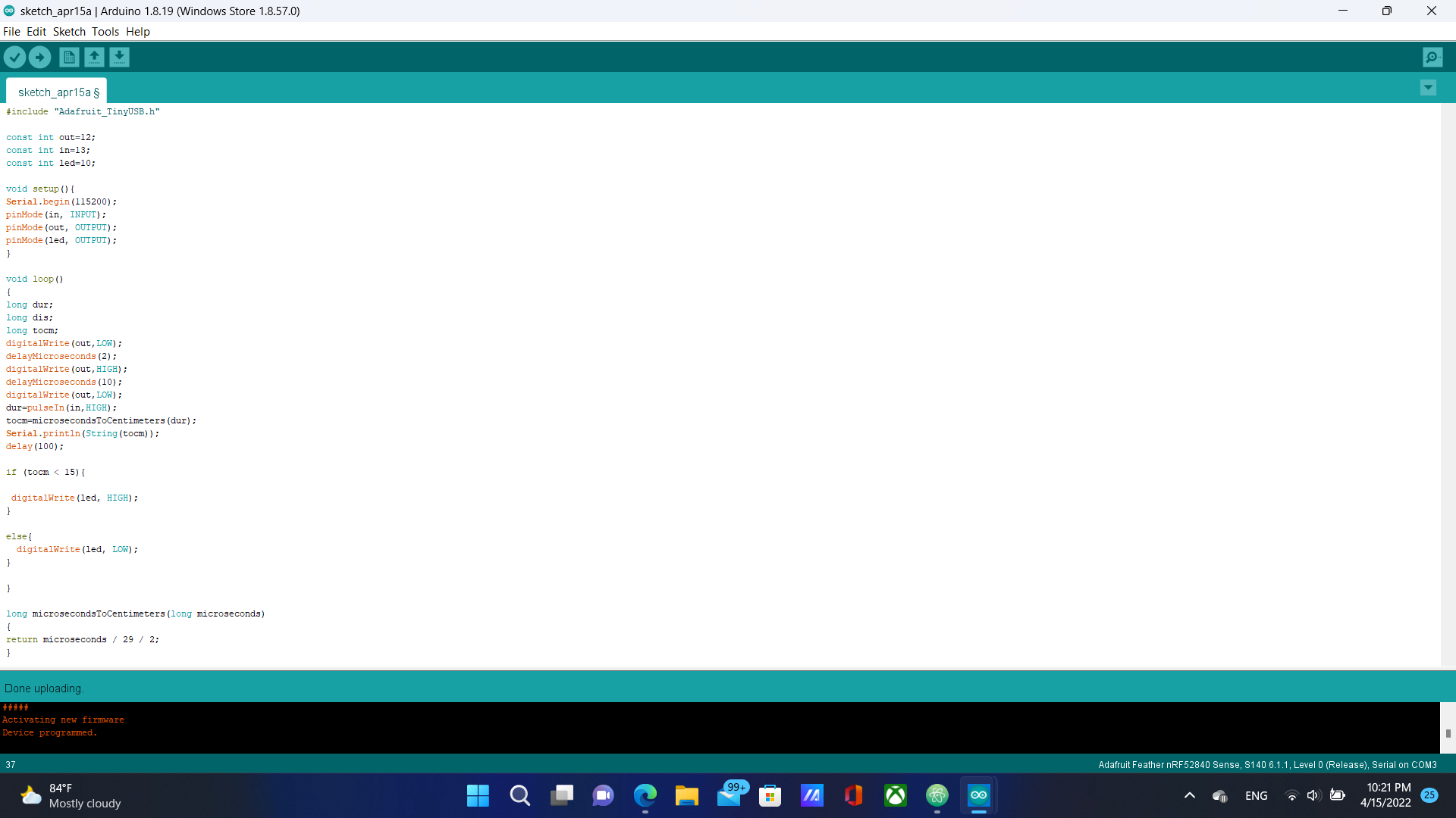
In order to program the circuit to measure distance, we need to add some commands within the code. I commented the code to explain the steps:
the video below shows the functioning circuit:
Output
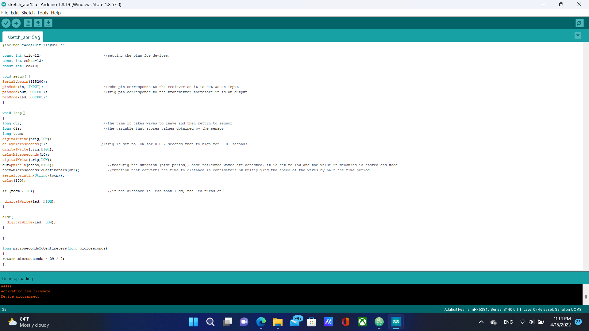
For the second assignment, we had to program an output device to do something. I chose to add an LED to my circuit and program the circuit to turn the led on when an object is within 15cm away from the sensor. I connected a pink led to pin number 10 on my circuit.
I added an if statement in the code that turns the led on when the condition of the object being within 15cm from the sensor is met.
When the sensor detects an object a distance of 15cm away, a signal travels through the echo pin to the microcontroller. the microcontroller then sends a signal through pin number 10 that turns on the led.
through this process, I understood how external measurements can be used to turn on output device.
You can download the code from here which includes the output LED
you can view the circuit in TinkerCAD from here and download the design file from here
Fortunately, I did not experience any major problems aside form one error when uploading the code to the circuit which was fixed quickly by choosing the right board in the port menu.