LARGE FORMAT CNC MACHINE CUTTING
This week, I have been introduced to the large CNC cutting machine used to cut wood in order to assemble big designs such as chairs and tables. The piece of wood used is of dimensions 240x130x1.2.
Assignment
The design
I started by looking for a design online and decided to go with a gaming desk of my own design. I started designing the desk in Fusion 360. The design was quite simple.
I started by designing the desk itself:
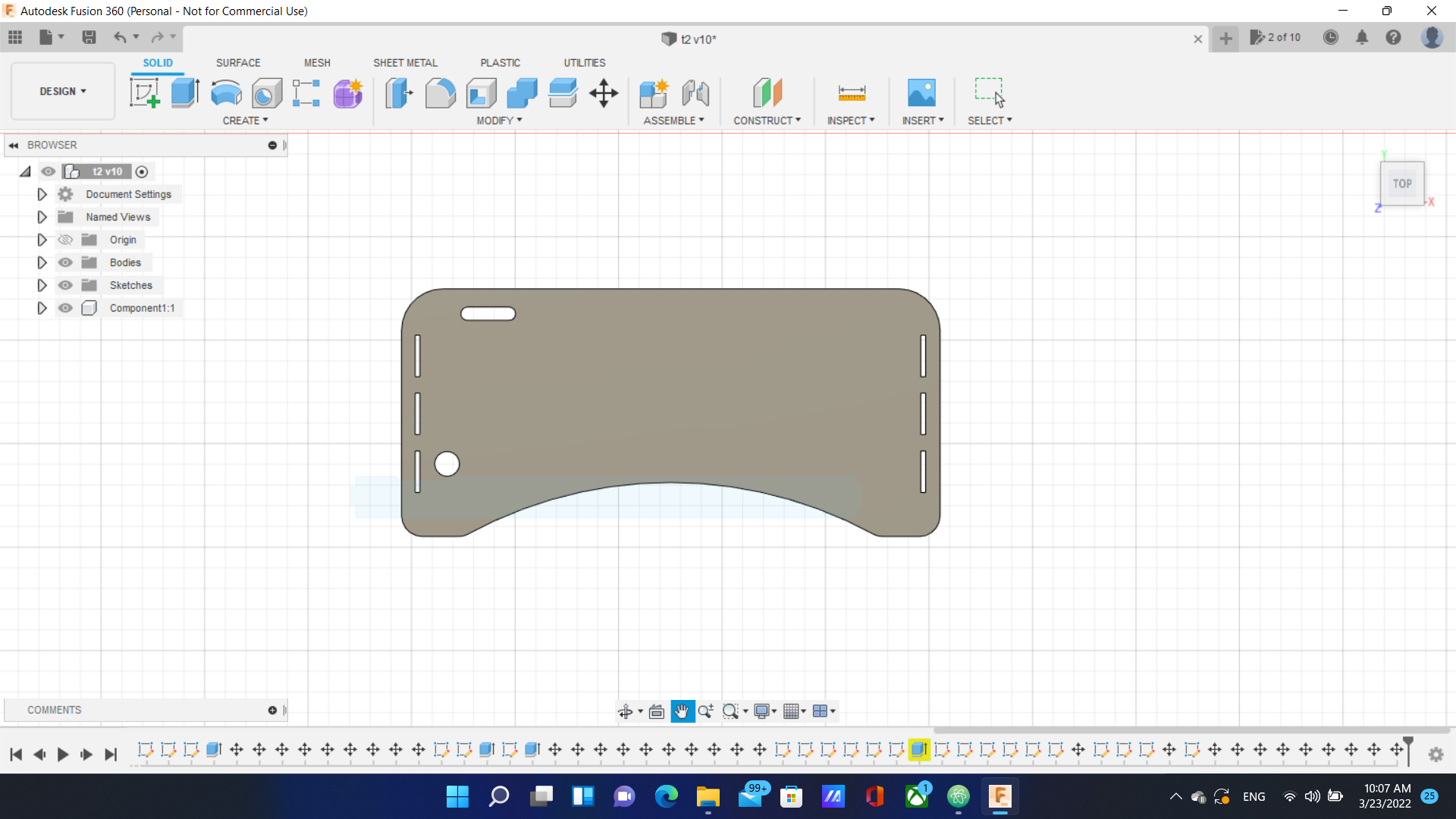
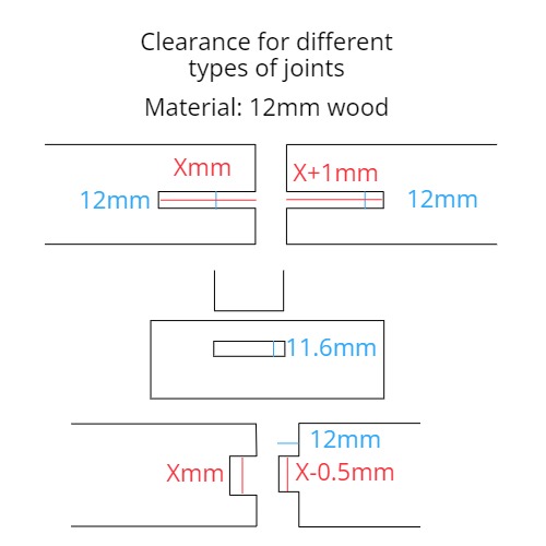
I chose the length to be 130cm and the width 60cm. I also added holes for the joints with widths of 1.16cm, lengths of 10cm and separated by 4cm. The width is the standard for the type of joint I chose for the specific wood type as shown below:
I also added a hole for drinks and another one for wires and rounded the edges to my liking.
Next, I designed the legs. I took the total height to be 1m and made 3 joints of 1.2cm height with rounded edges. I made the distance between the joints 4cm and their base length 10cm as shown below:
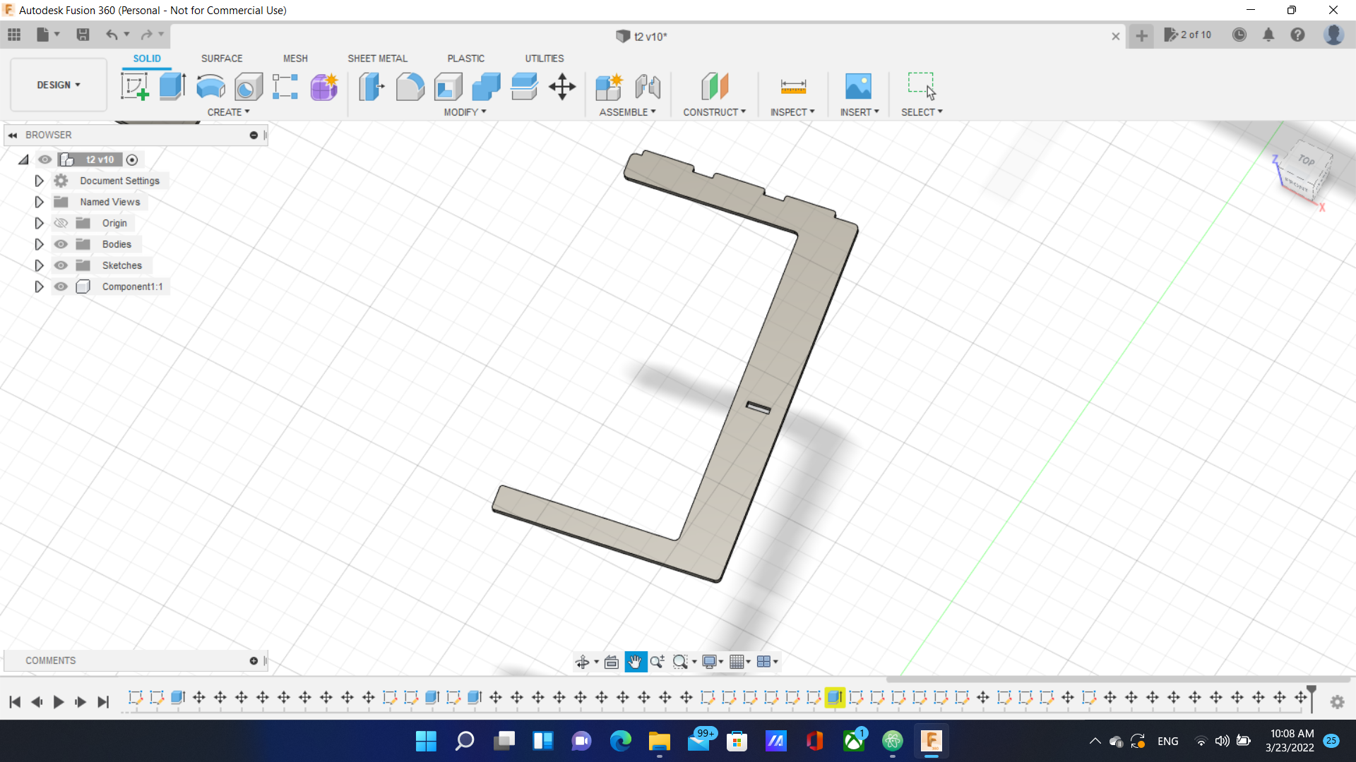
I also added a hole of length 4.5cm, width 1.16cm on both legs.
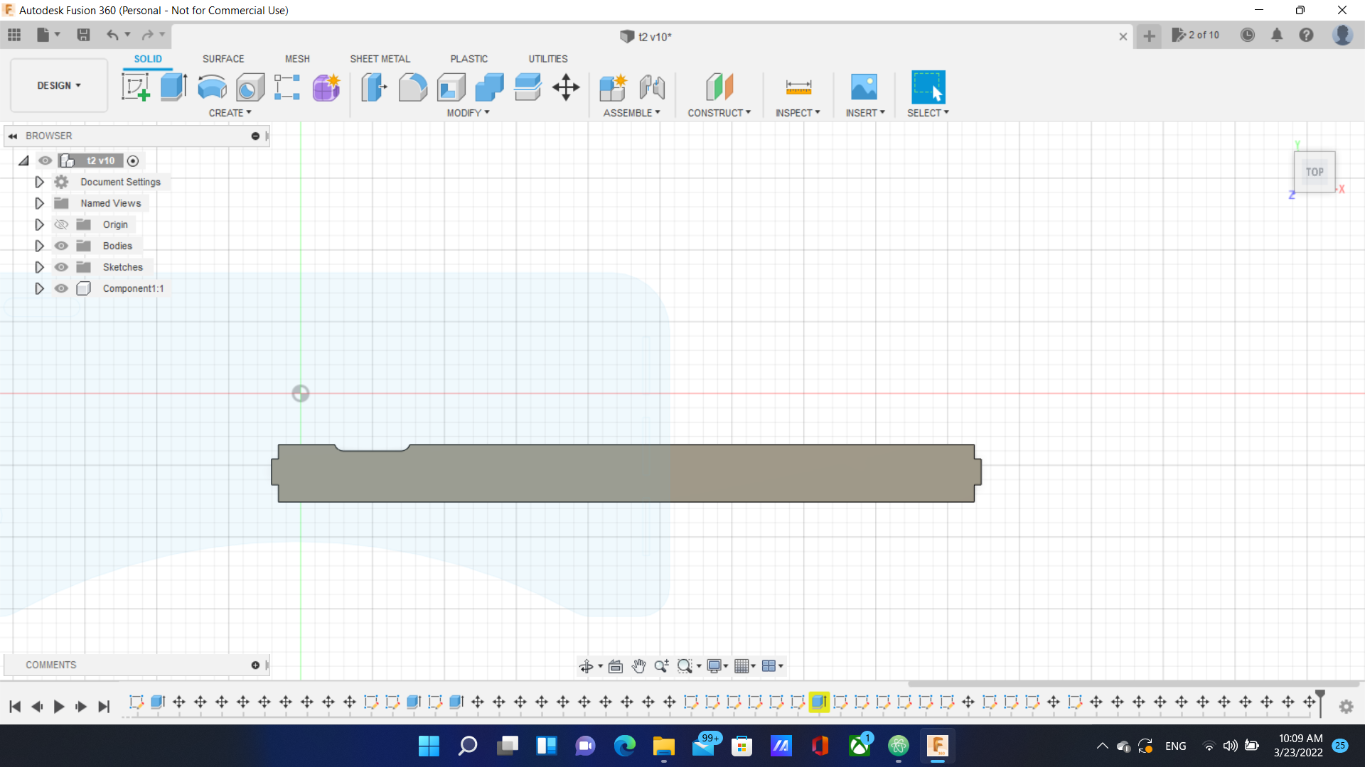
Next, I made a support piece that goes between the legs of total length 123.4cm. I made a joint of length 1.2 cm on each end and rounded the edges as shown below:
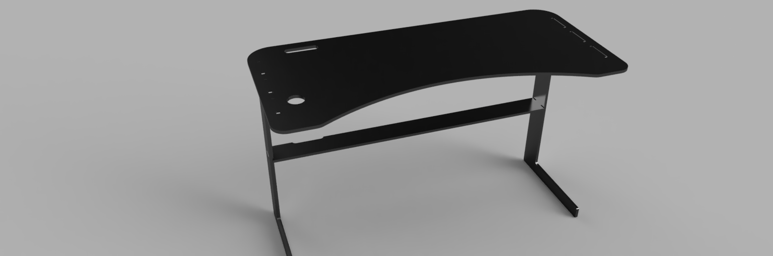
Finally, I extruded the parts by 1.2cm and assembled the table:
you can download the design from here and the editable fusion version.
Toolpath and Cutting
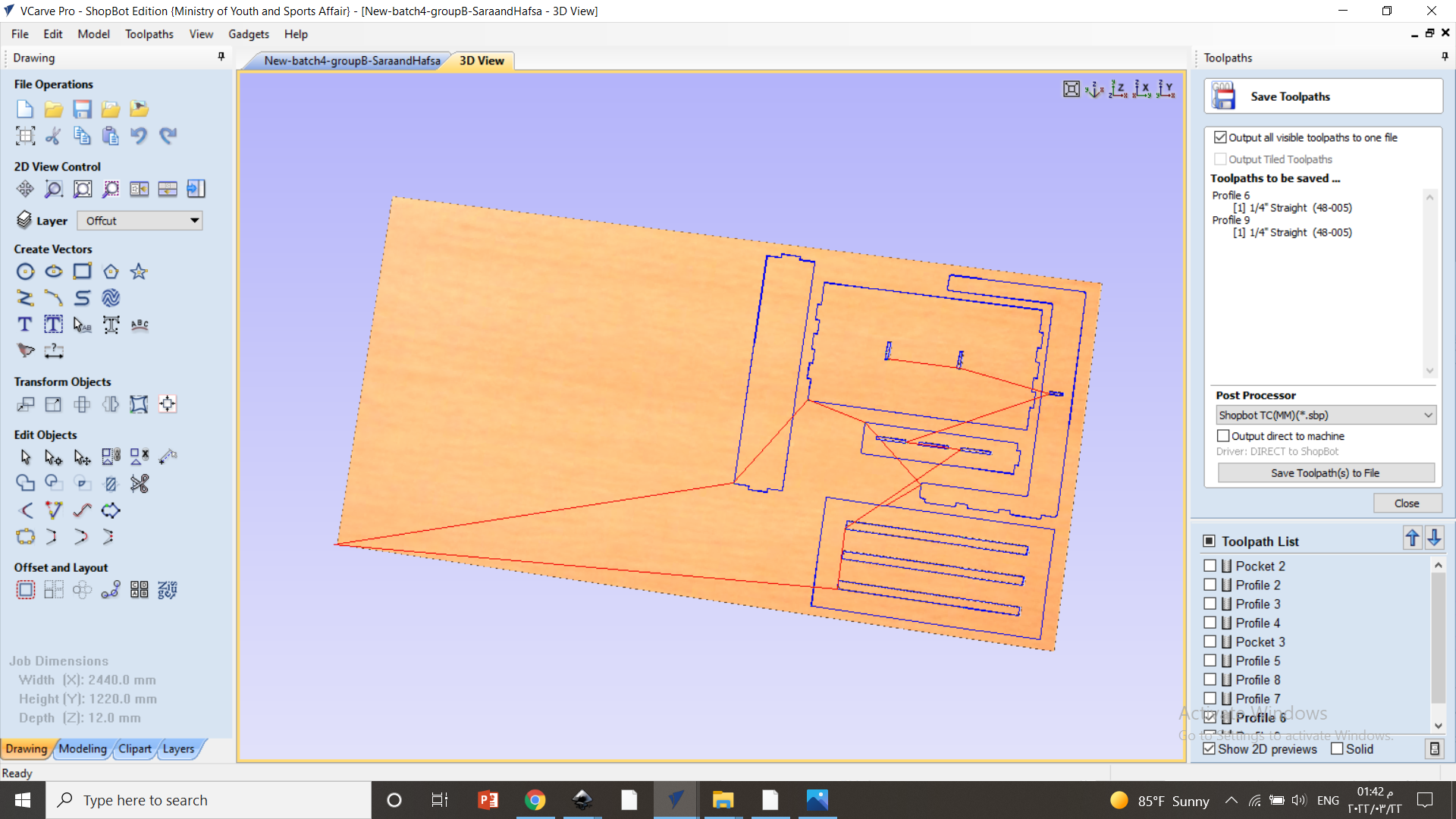
The next steps was to cut the table. I started with uploading the exported dxf file into the special software Vcarve PRO and the 3D parts were converted to 2D parts.
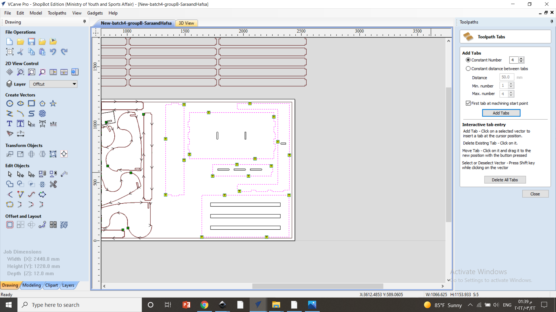
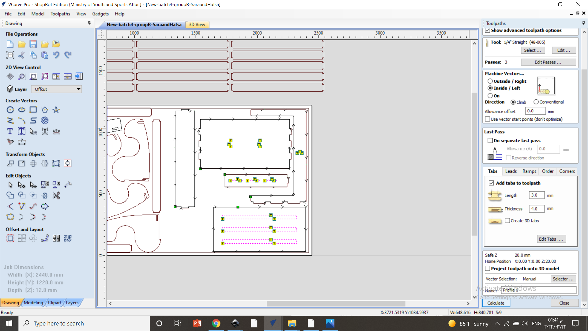
I arranged the pieces on the board in a way that conserves as much space as possible. Then, I added tabes (thickness of 4mm and length of 3mm) along the defining lines of the parts. These tabes are used to keep the parts intact while the cutting process continues to prevent deformities.
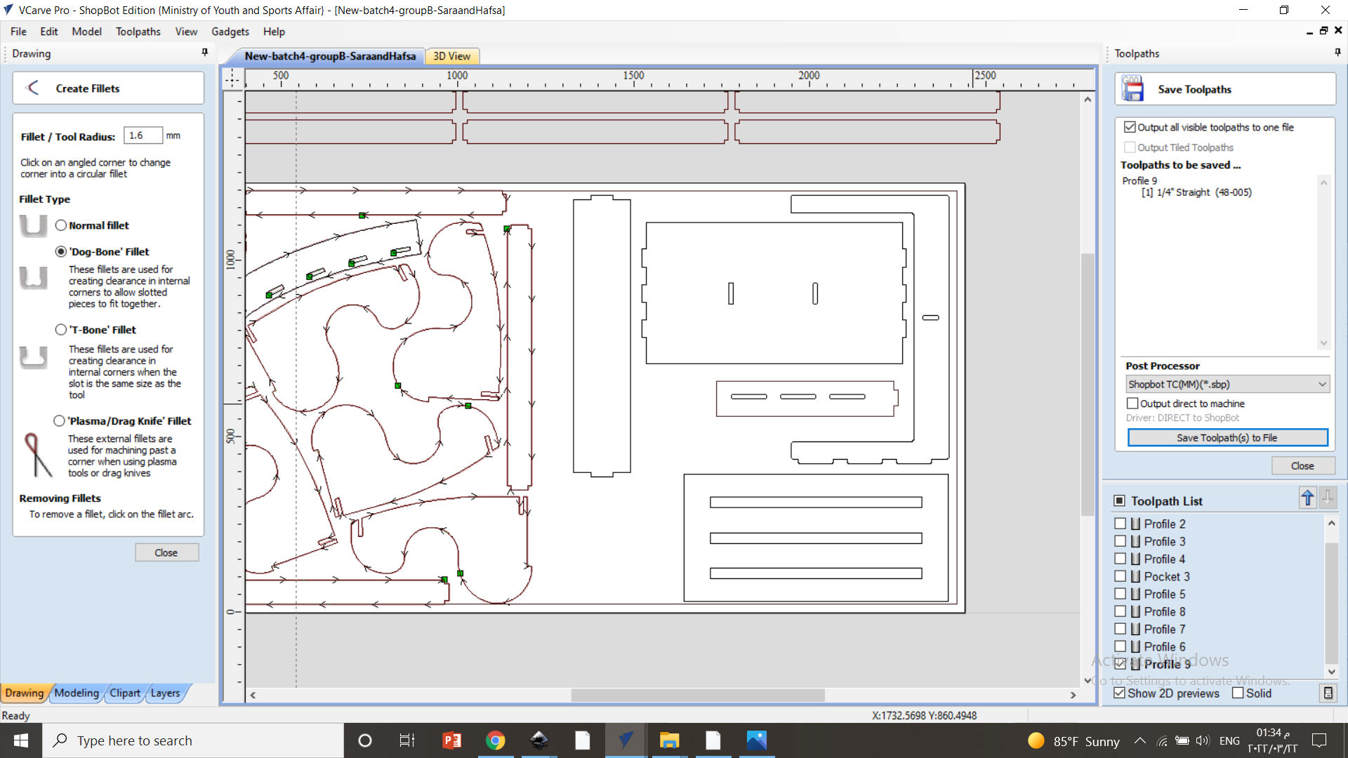
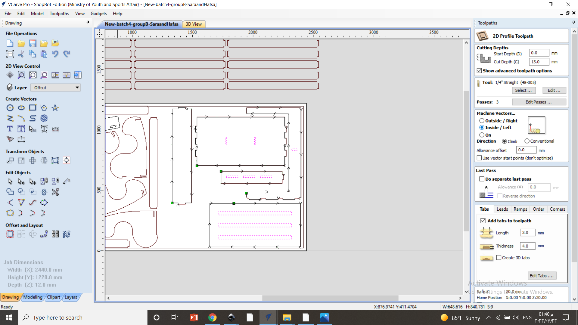
I adjusted the setting for cutting the holes such that the cutting blade starts cutting from the inner rim of the lines that represent the holes as shown below.
After that, I added tabes for the holes as well.
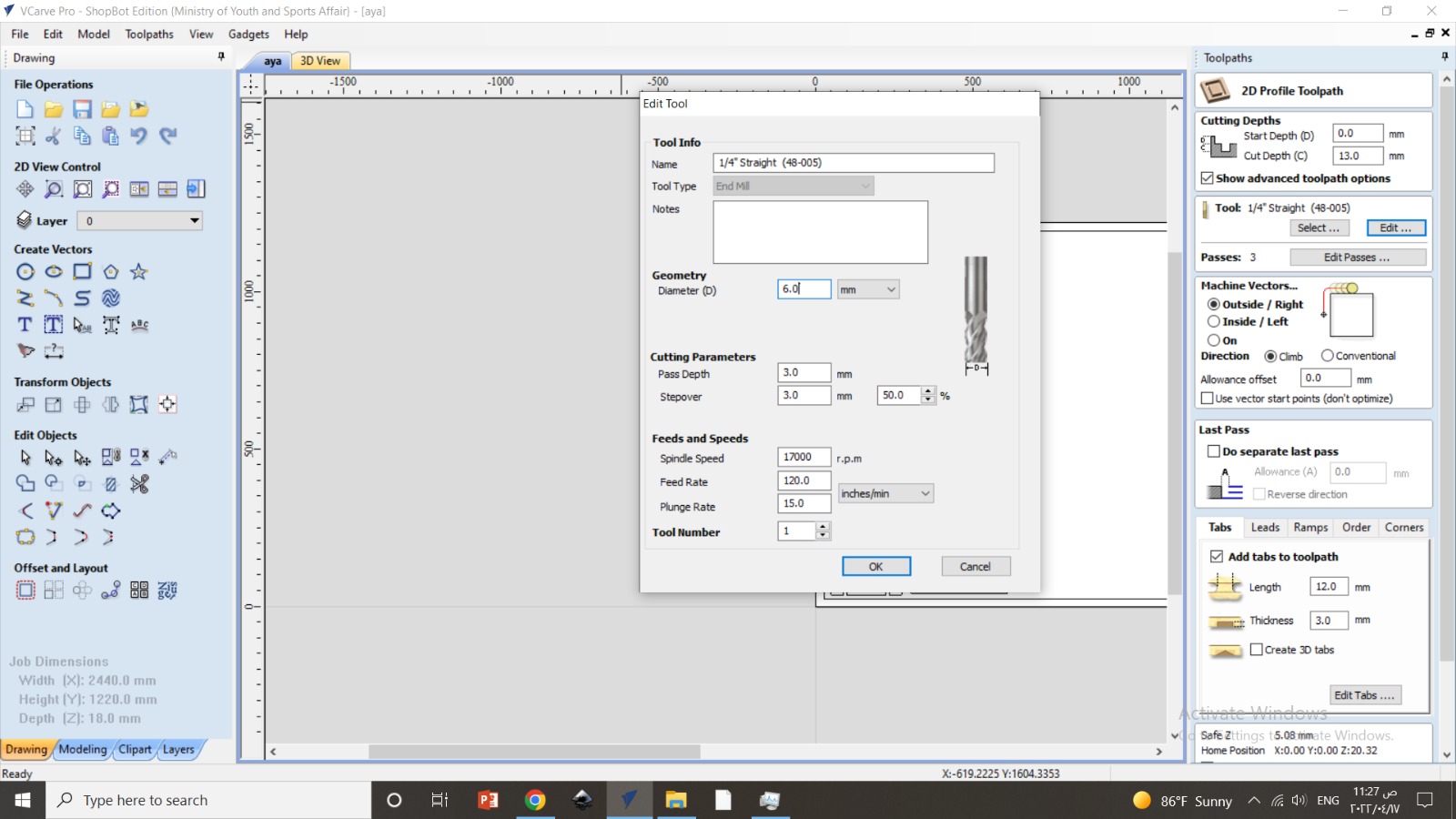
I also defined the cutting depth (13mm), the thickness of the blade (initially 3mm) and the speed of the moving blade head (15 inch/min), The feed rate (120), and the rotational speed of the blade (17000 rpm).
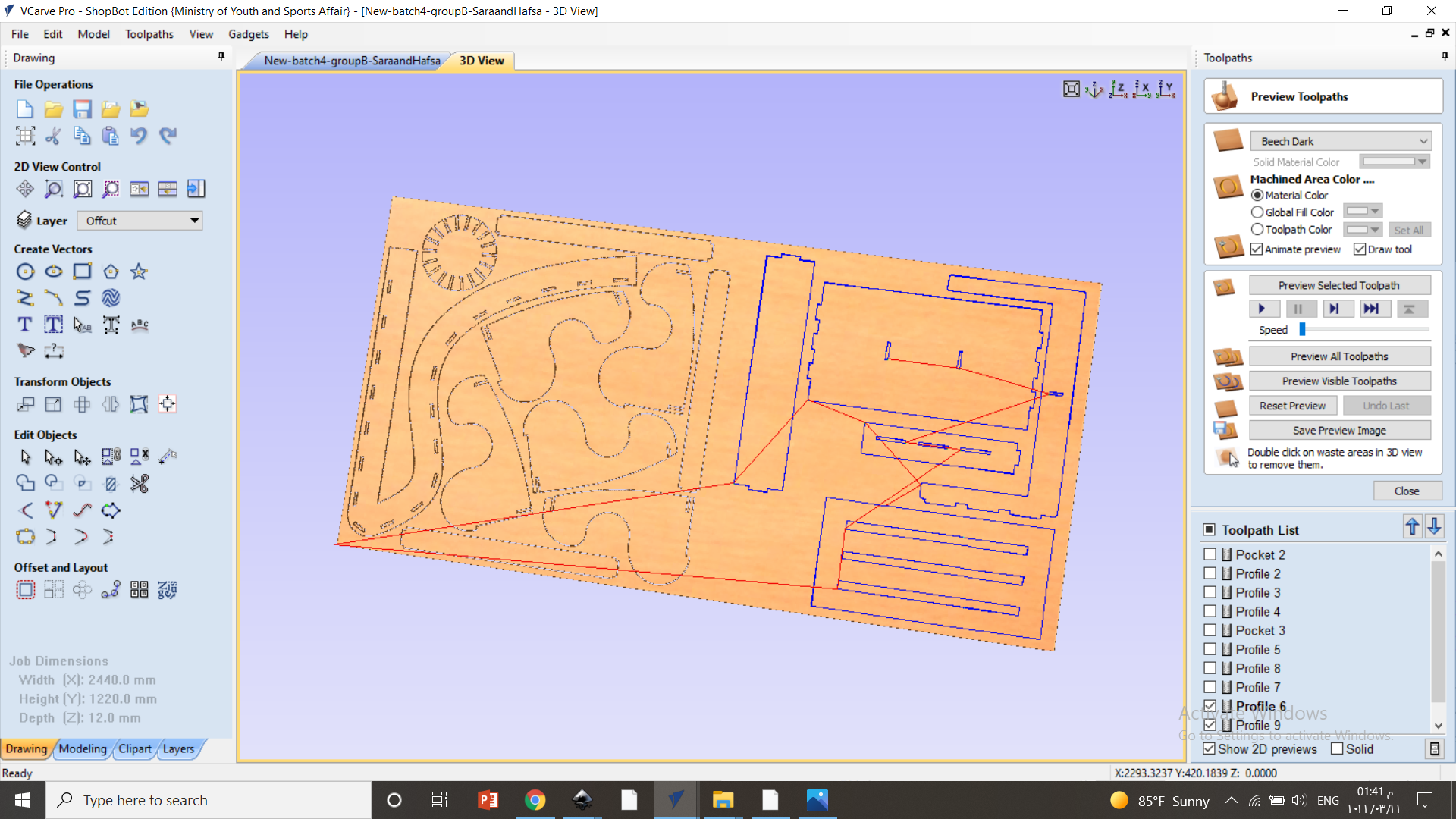
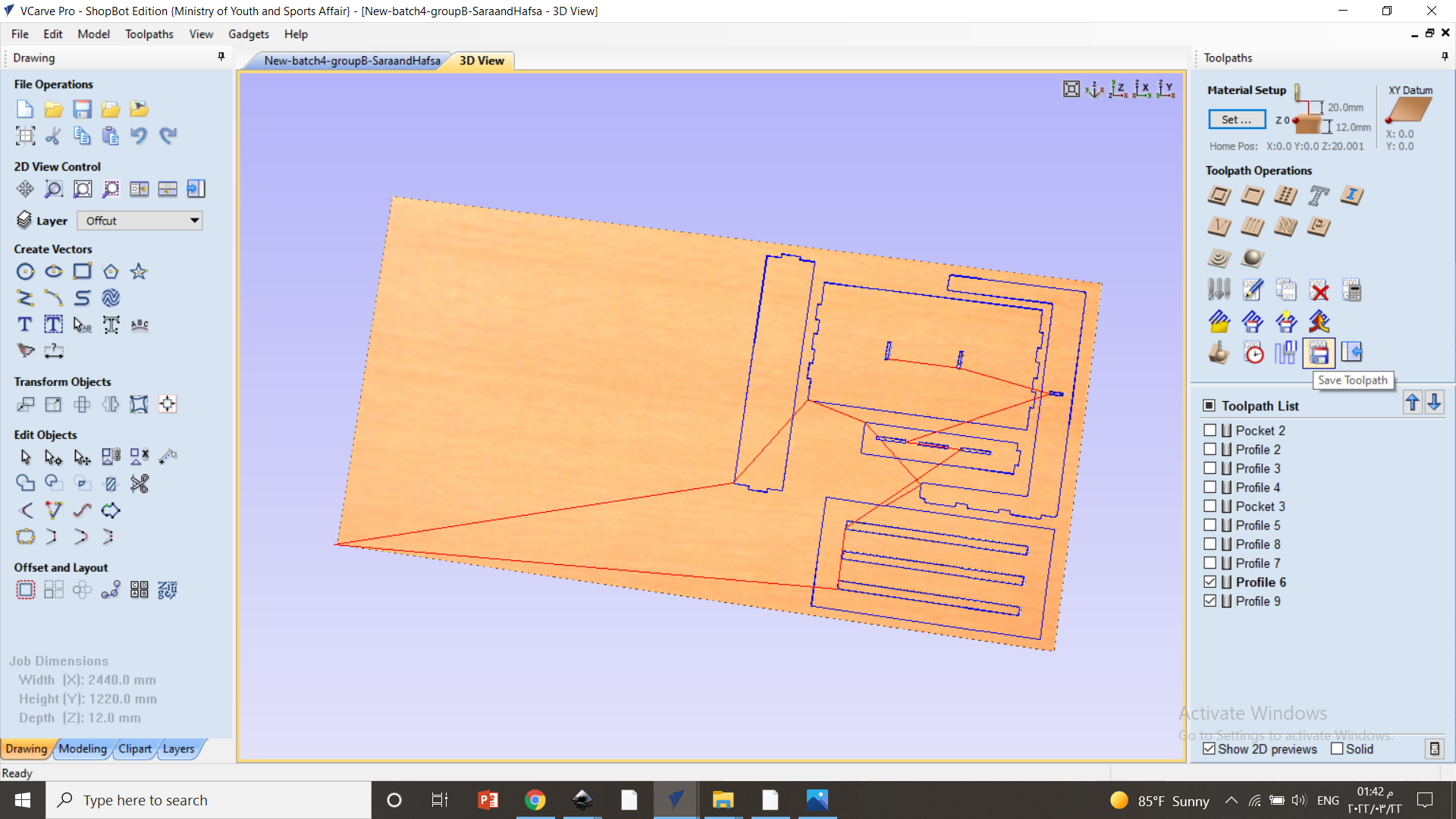
Then, I did a preview of the toolpath.
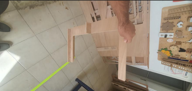
To test the Toolpath I made, I started by cutting a leg and a small piece to test the strength of the joints. The joint turn out to be incredibly strong:
It is worth mentioning that before every cutting process started, I sat the blade location to the origin and above it.
After the testing process, The pieces were ready to be cut. So I started the cutting process after turning on the vacuum pump and the process took around 30 minutes to complete. After the pieces were cut, I took them home to assemble them.
Unfortunately, I discovered that the machine cut the holes from outside their rim even though I selected the option to cut from inside the rim which made the holes wider. so I couldn’t fit the parts perfectly together.
These are the final cut pieces:
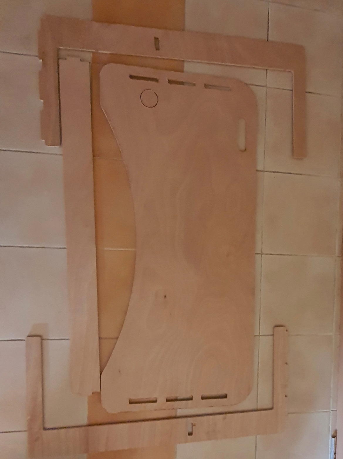
Due to the holes not being of desired size, I couldn’t join the pieces together.
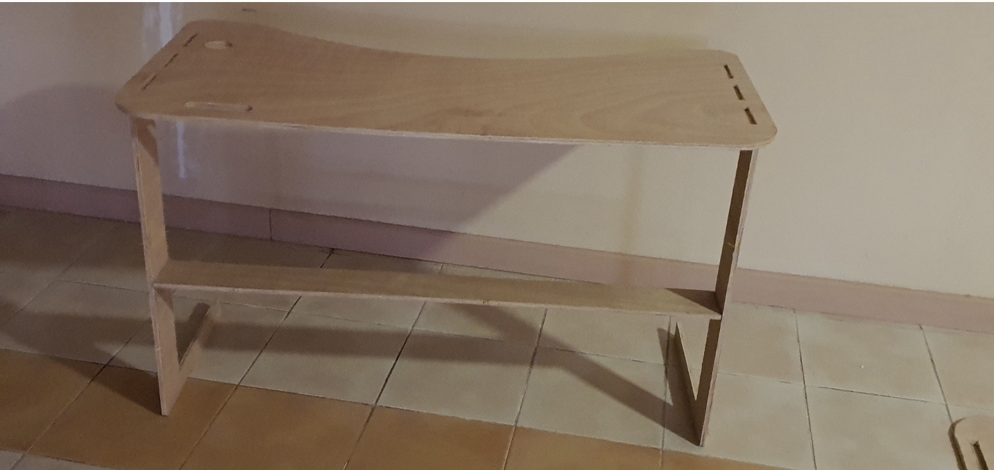
After re-cutting the pieces, I was able to join them together and use the table.
Problems I faced
Midway through the cutting process, the blade broke and we had to replace it with the 6mm one and then continue the cutting process.
Group assignment
You can check Yousif’s website to view the group assignment.