4. Embedded programming
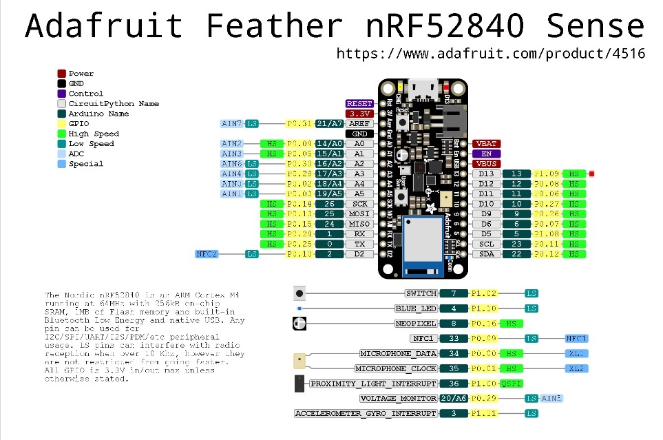
this week I learned and implemented Embedded programming in my microcontroller board , the microcontroller board I Used is Adafruit nRF52840 Feather , there are 3 led attached to it and a temperature sensor , which I believe will useful for me in my final project.
Power Pins
3V: This pin is connected to the output of the on board 3.3V regulator. It can be used to supply 3.3V power to external sensors, breakouts or FeatherWings.
USB Power (USB): This is the voltage supply off USB connector, nominally 4.5-5.2V.
and as shown in the figure there are 6 analog pins (A0 TO A5).
Embedded system is a system that contains a software and hardware , together they aim to reach a specific target, like a washing machine for example. why this so important ? because the circuits used to be fixed , but after the addition of microcontrollers we were able to make so many changes without changing the circuit configuration.
4.1 Embedded programing and Arduino board
4.1.2 Individual assignment
Arduino board is simple inexpensive open source development board (hardware and software).
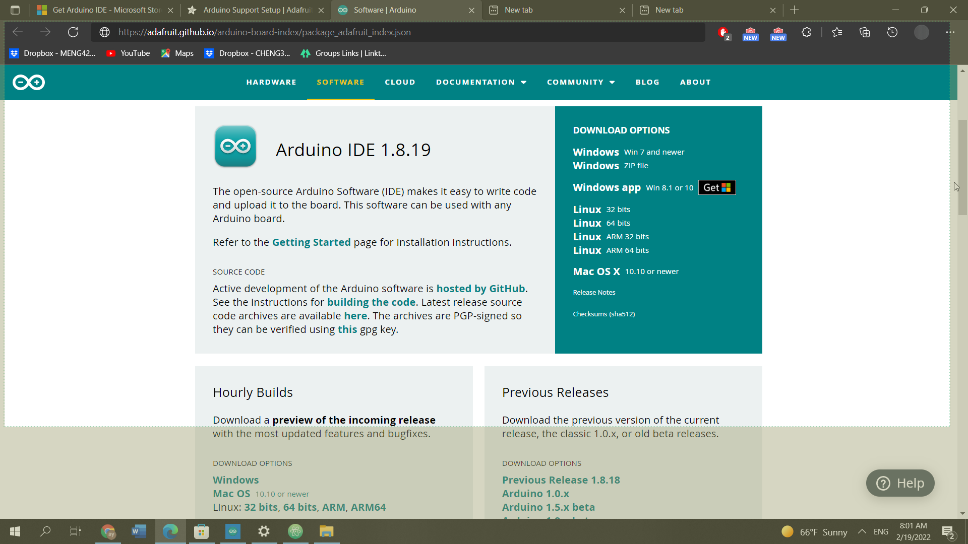
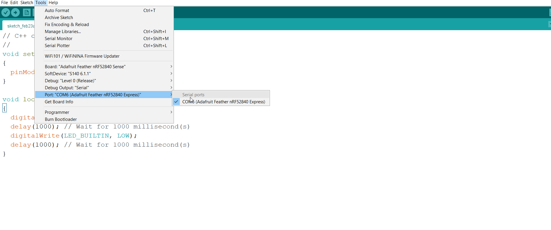
first , I started by downloading the Arduino software from this link arduino
and then I managed to follow the steps shown here Adafruit Feather nRF52840 to install my board (Adafruit Feather nRF52840) setup in the Arduino software, hence my computer will be able to identify the board.
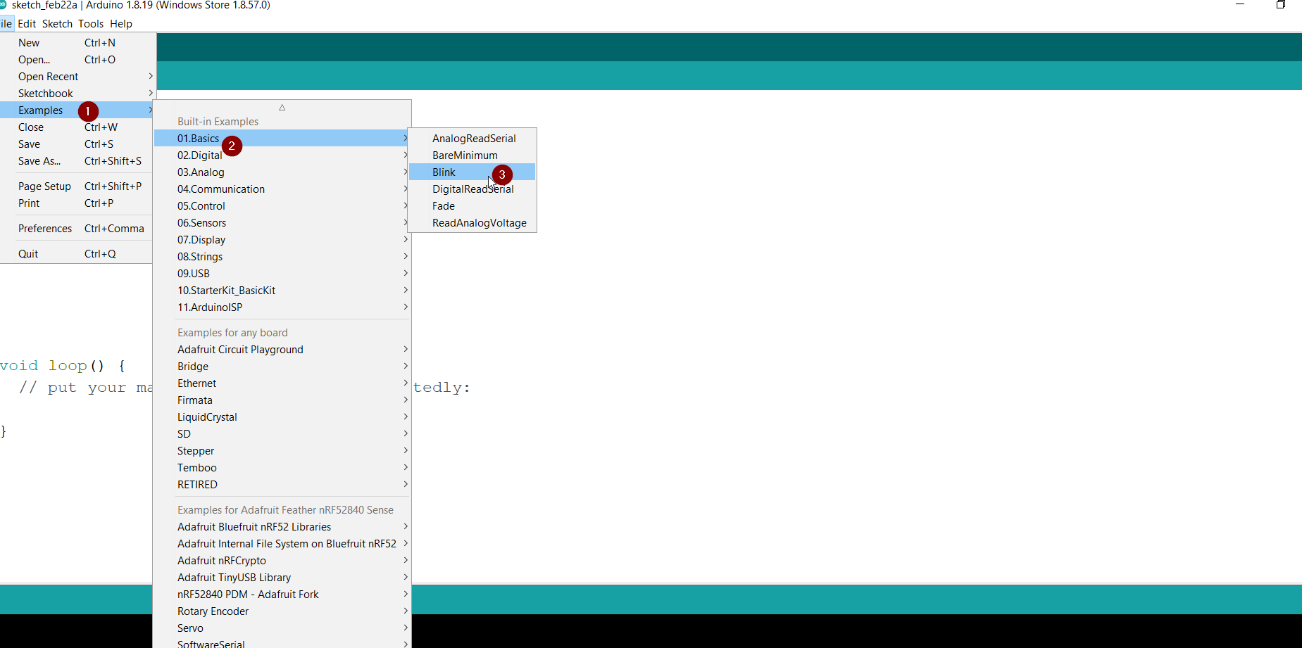
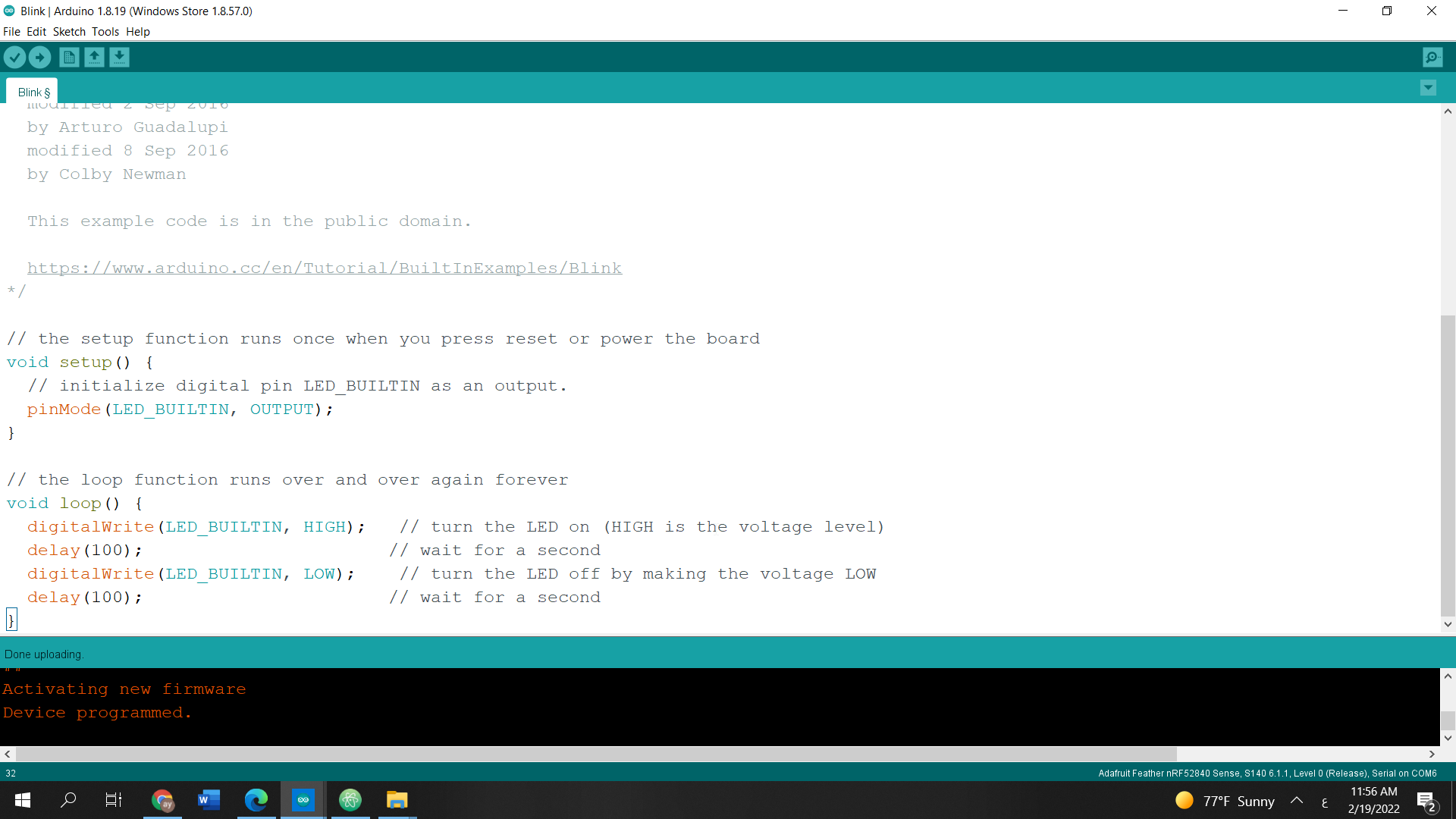
and once I managed that successfully I Tried one of the examples “blink ” in my microcontroller board , the purpose of program is to make the led light attached to the board blink for one second
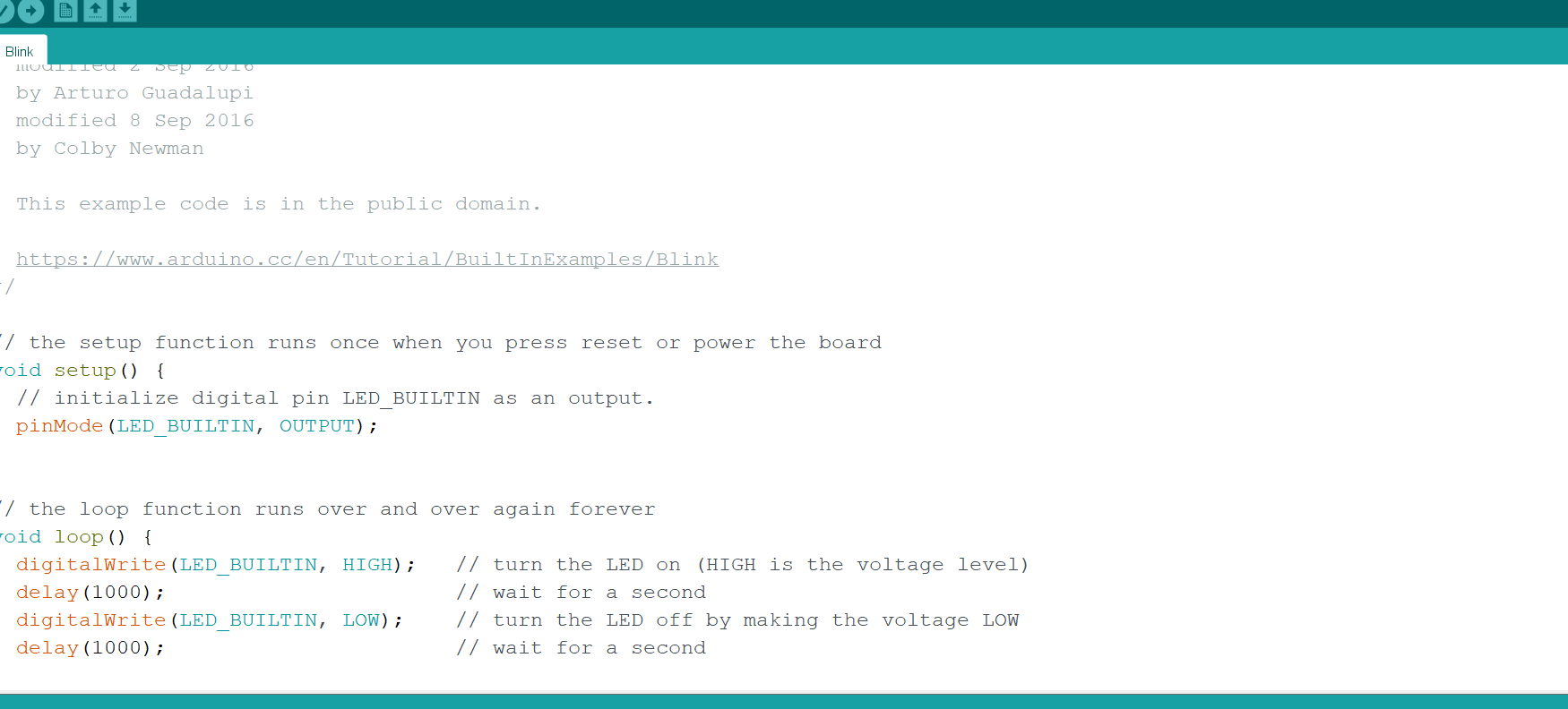
and the result was as shown first trail
and then I just changed the blinking timings from 1000 millisecond (1 second) to 0.1 second (100)
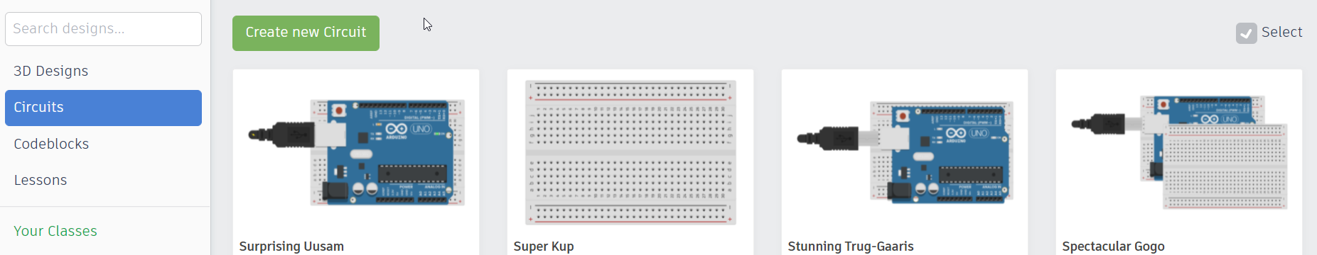
Then I Tried tinkerCAD app to tryout some different codes that I can Virtually simulate it first in the Arduino board before transferring it to my adafruit microcontroller board
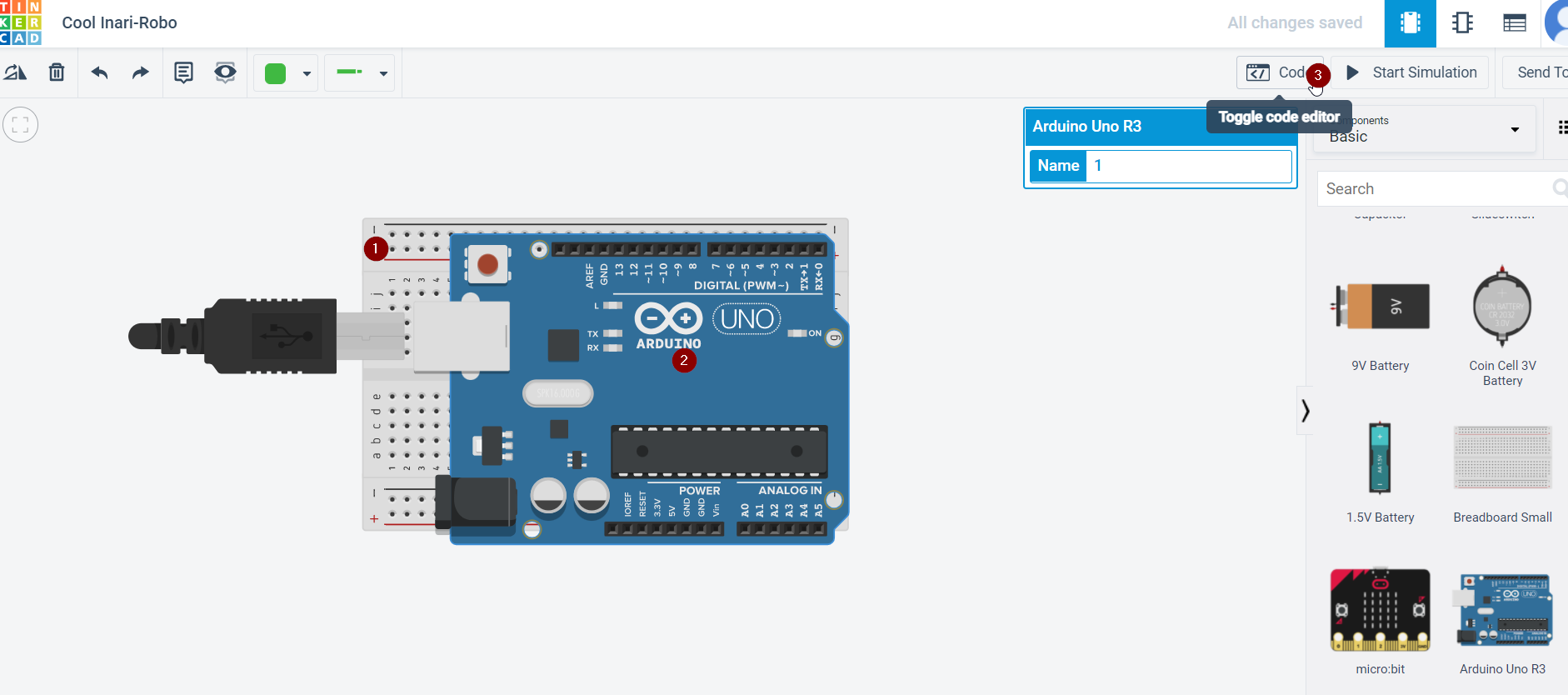
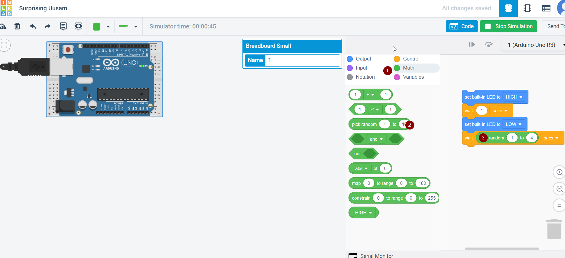
then I tried to make the delays of blinking to be a random number between 1-5 second , so I used tinkercad circuit simulation and then I implemented the code IN MY microcontroller the my board
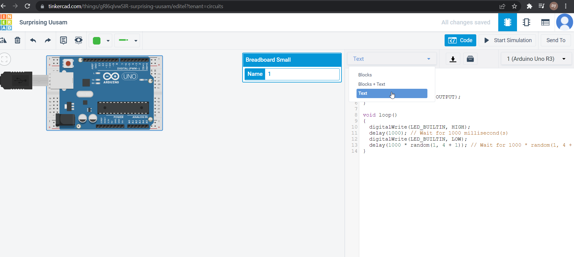
and before that I made sure that my microcontroller is properly attached to my board , by clicking twice in button and then press port and I download it
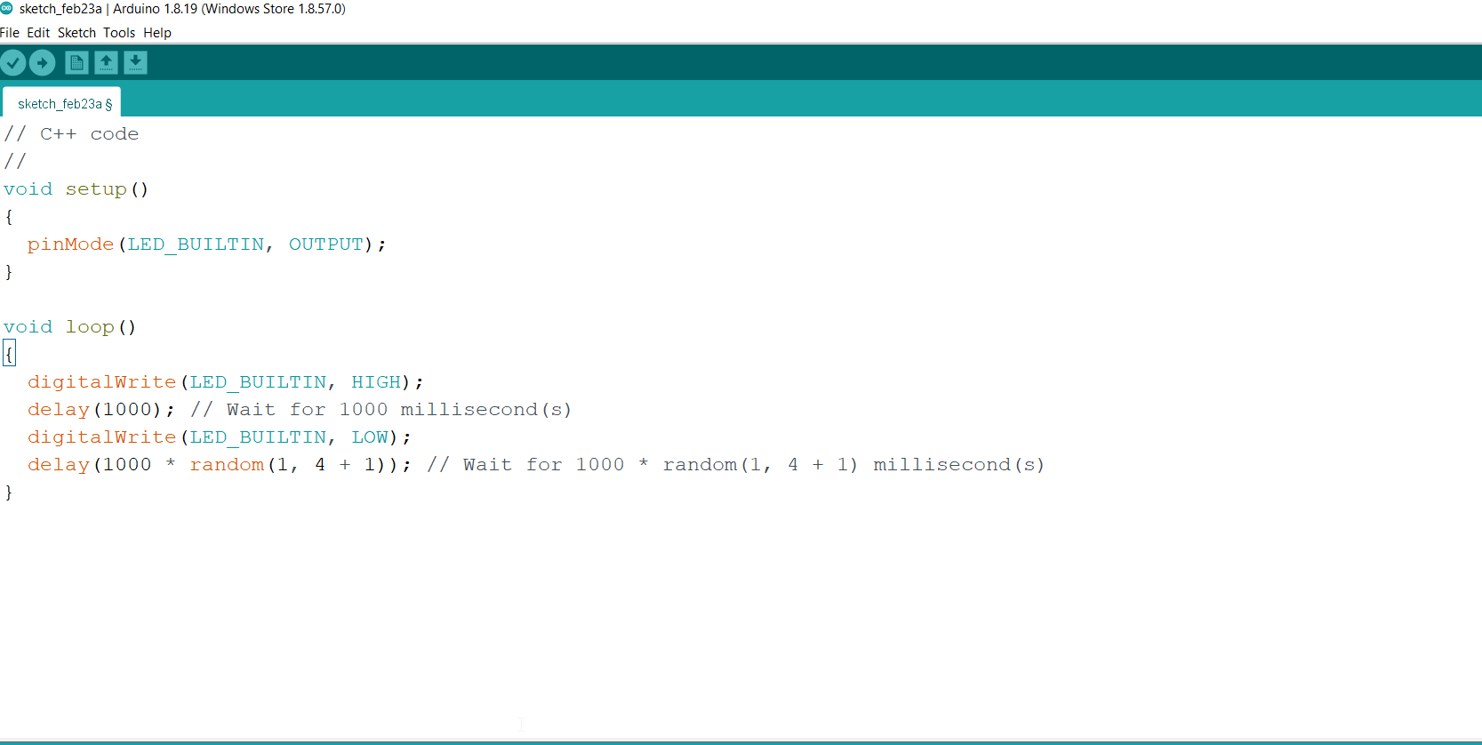
// C++ code
//
void setup()
{
  pinMode(LED_BUILTIN, OUTPUT);
}

void loop()
{
  digitalWrite(LED_BUILTIN, HIGH);
  delay(1000); // Wait for 1000 millisecond(s)
  digitalWrite(LED_BUILTIN, LOW);
  delay(1000 * random(1, 5 + 1)); // Wait for 1000 * random(1, 5 + 1) millisecond(s)
}
and the result is shown here
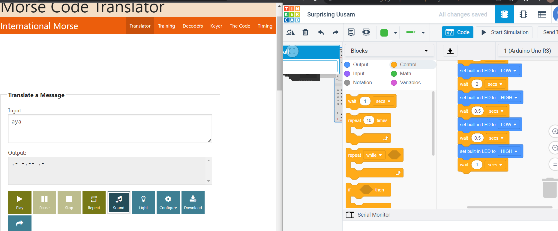
and then I Tried to write my name (aya) in Morse code and then translate it through the led
// C++ code
 //
 void setup()
 {
   pinMode(LED_BUILTIN, OUTPUT);
 }

 void loop()
 {
   digitalWrite(LED_BUILTIN, HIGH);
   delay(500); // Wait for 500 millisecond(s)
   digitalWrite(LED_BUILTIN, LOW);
   delay(500); // Wait for 500 millisecond(s)
   delay(1000); // Wait for 1000 millisecond(s)
   digitalWrite(LED_BUILTIN, LOW);
   delay(2000); // Wait for 2000 millisecond(s)
   digitalWrite(LED_BUILTIN, HIGH);
   delay(1000); // Wait for 1000 millisecond(s)
   digitalWrite(LED_BUILTIN, LOW);
   delay(500); // Wait for 500 millisecond(s)
   digitalWrite(LED_BUILTIN, HIGH);
   delay(1000); // Wait for 1000 millisecond(s)
   digitalWrite(LED_BUILTIN, LOW);
   delay(1000); // Wait for 1000 millisecond(s)
   digitalWrite(LED_BUILTIN, LOW);
   delay(2000); // Wait for 2000 millisecond(s)
   digitalWrite(LED_BUILTIN, HIGH);
   delay(500); // Wait for 500 millisecond(s)
   digitalWrite(LED_BUILTIN, LOW);
   delay(500); // Wait for 500 millisecond(s)
   digitalWrite(LED_BUILTIN, HIGH);
   delay(1000); // Wait for 1000 millisecond(s)
and the final challenge was to control the led from serial monitor , serial monitor allows the user to send commands from the pc to the board.
here I tried to control the LED light by simply sending a command 1 to open and 0 TO close and this was the result third trial
and here the code , I started it first from the Blink example and then tried to modify it a bit bu following a youtube tutorial
  */

  // the setup function runs once when you press reset or power theboard
  int entry =0;
  void setup() {
    // initialize digital pin LED_BUILTIN as an output.
    pinMode(LED_BUILTIN, OUTPUT);
    Serial.begin(9600);
  }

  // the loop function runs over and over again forever
  void loop() {

  if(Serial.available()>0){

    entry= Serial.read ();

    if(entry=='1'){

  digitalWrite(LED_BUILTIN, HIGH);

      }
    else if(entry=='0'){digitalWrite(LED_BUILTIN, LOW);
    }


    }

  }
4.1.2 group assignment
the documentation of the group assignment are in fatima.helal website
4.3 references
3 Adafruit Feather nRF52840 data sheet