6. Large format CNC (computer controlled Machining)
this weeK I learned how to set up and use CNC machine.
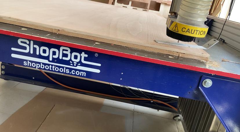
A CNC router is a machine . Steel, wood, aluminum, plastic,can all be cut with this type of CNC machine.
A CNC router has the ability to route tool paths using computer numerical control, allowing the machine to function. CNC routers decrease waste and boost production by creating a wide range of things in a fraction of the time it takes traditional machines.
6.1 CNC SET Up
for this assignment I used plywood to fabricate my design.
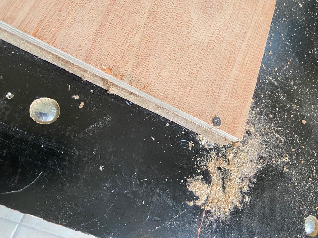
first my instructor made sure that the workplace is clean and to do that we used something similar to a vacuum cleaner cleaning by a vaccum this plywood shown in the video is what we call a sacrifice layer , because when the CNC router cut through the plywood to make a design it may go a little bit deeper and damage the needle or the machine , hence we are putting such a layer to be safe , after that we brought the new plywood and install it above the sacrifice layer and used nails and drill to stick it , you may notice that the nail are near the edges , again this a common safety practice, to make sure the cnc needle wont hit the nails.
here the Z axies been set up using this piece of meta that attached to the machine
6.2 safety measures
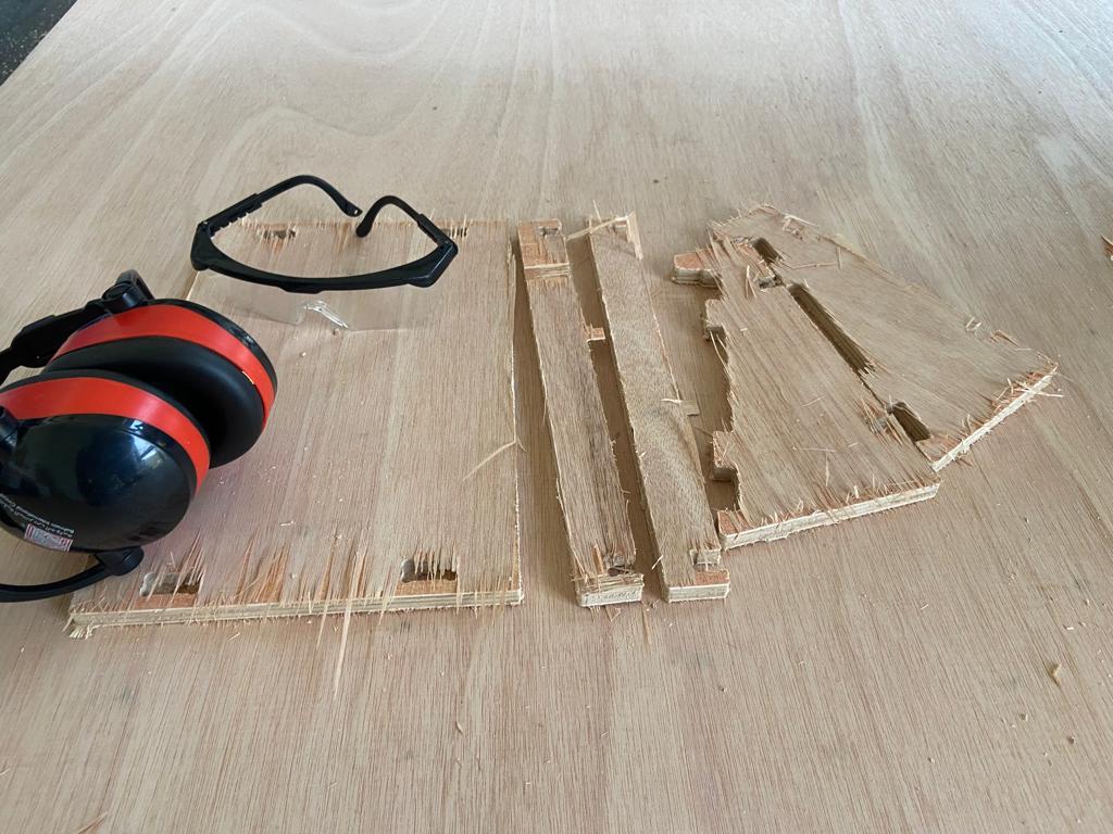
before goning to the class we made sure that we weare close shoses , and also we were given a glasses and noise cancleing headphones.
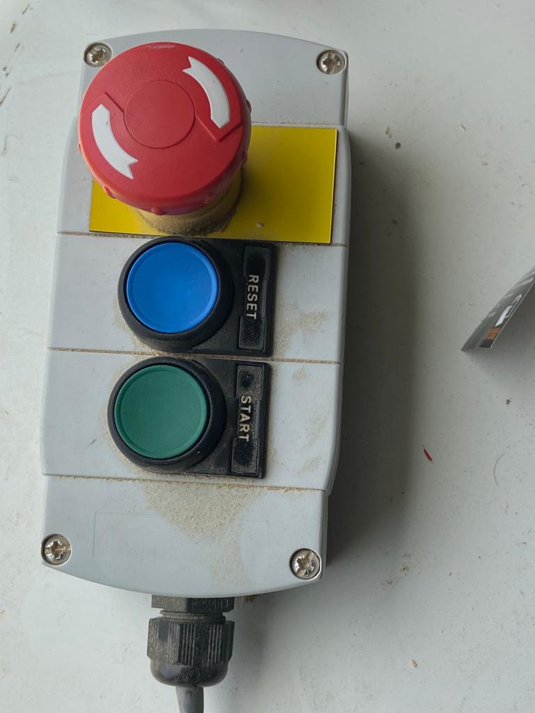
the red button is to stop the machine in case something happen (emergencies )
desgin
my sister was looking for a labtop stand for while , so I thought to design one for her using fusion 360 by follwoing this tutorial labtop stand tutorial
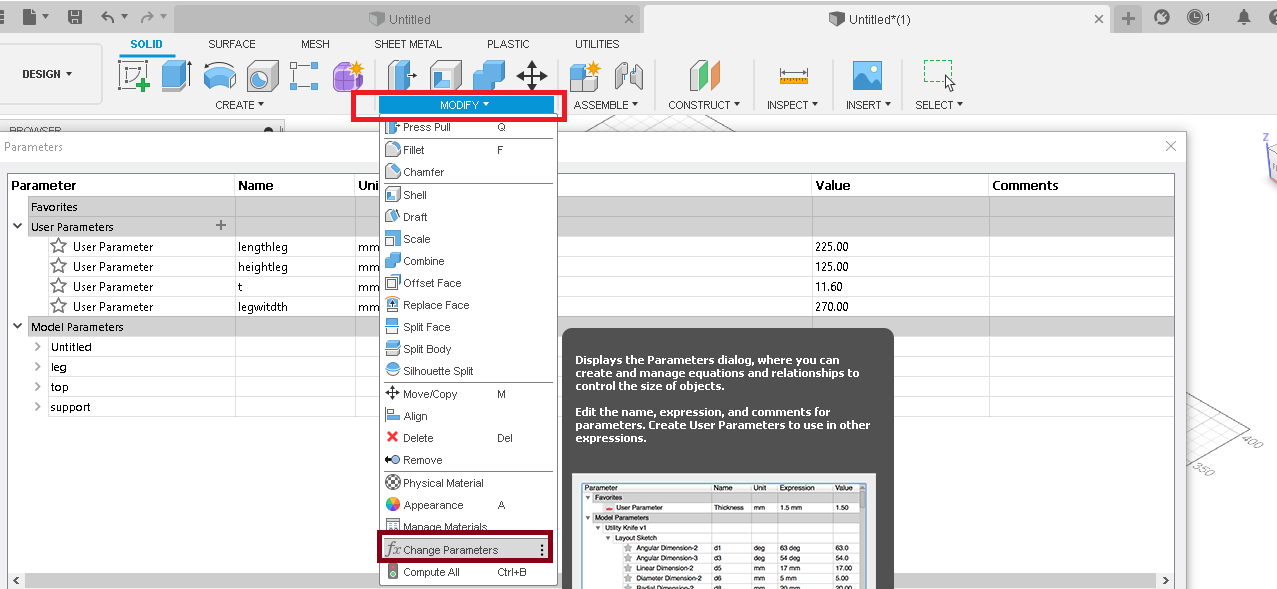
first Ive set the parametric table , and made sure that the thikness is equal to my plywod thikness 12mm , then my instructer suggested to decrease the thikness 1o 11.6mm as in the trails showed that 11.6mm is the perfect size for the joints
first I started by setting a parametric table that’s suits my sister laptop and the thickness of the material that I am gonna use , which was tested to be around 12mm hence the one I used was 11.6mm to ensure that the joints would tight enough with no lose ends
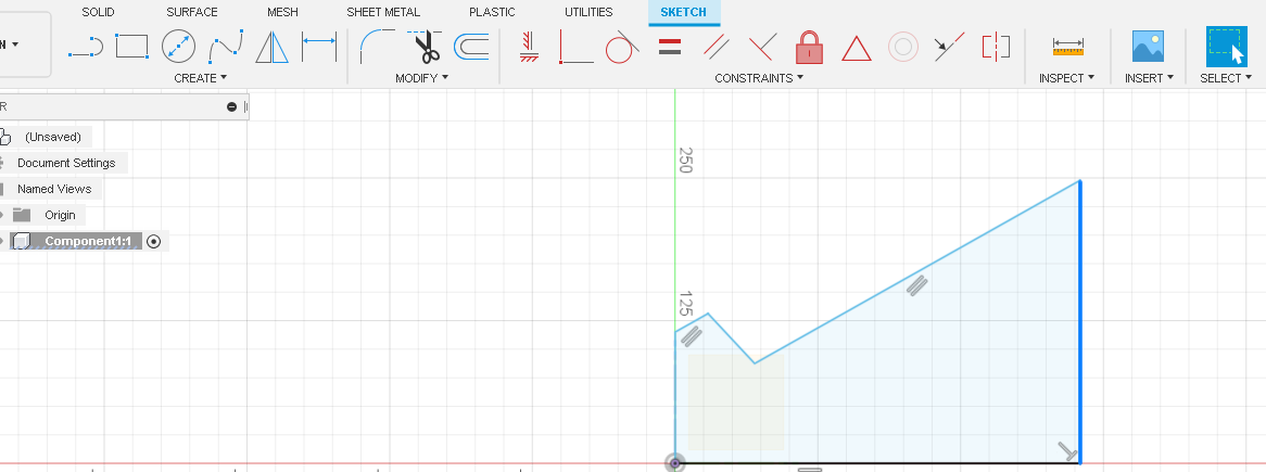
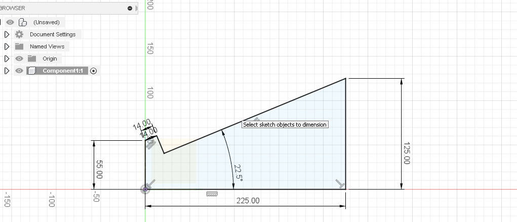
then I did a very rough shape for the stand leg then I used the dimension and set all the dimensions and constraints
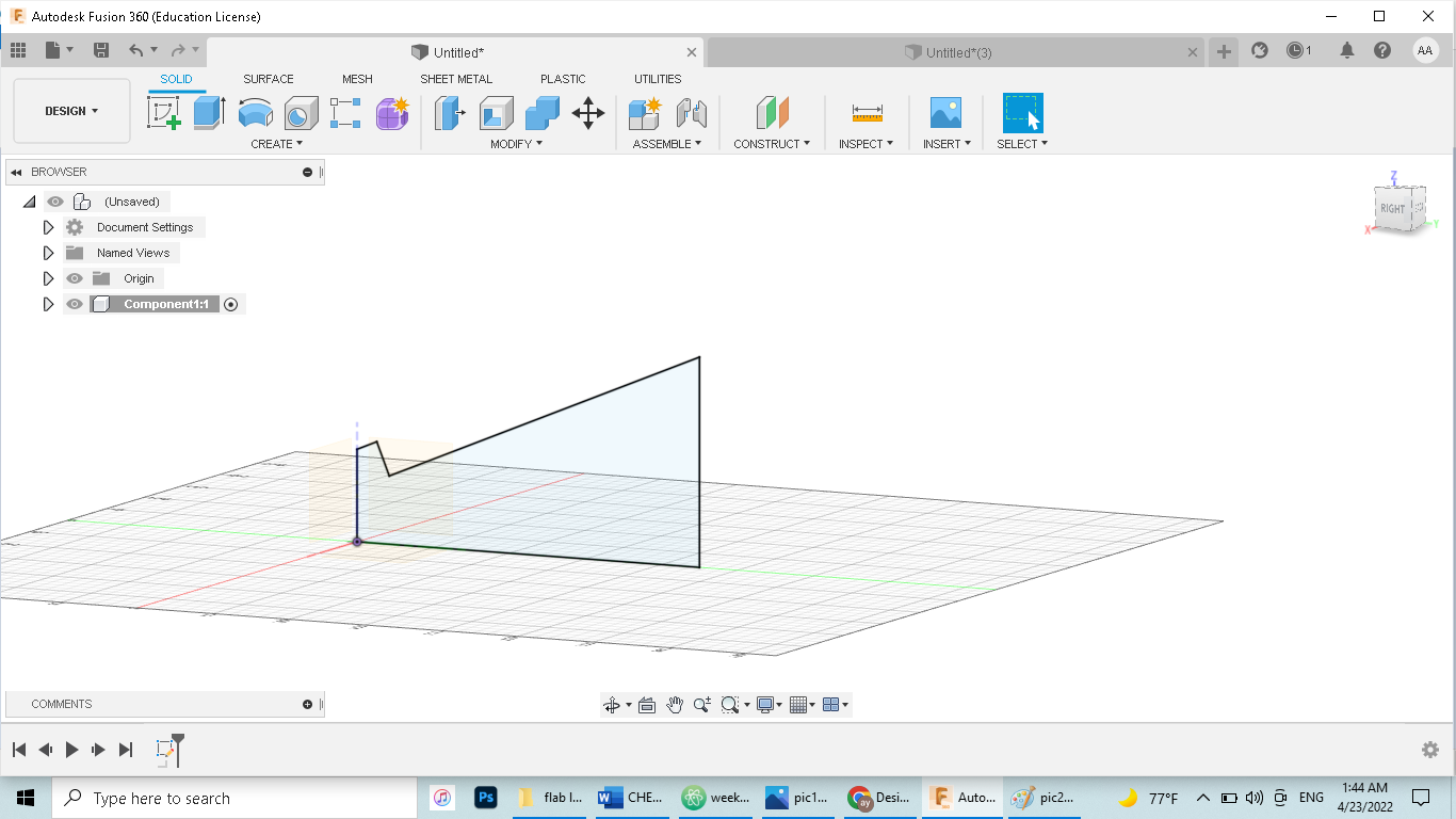
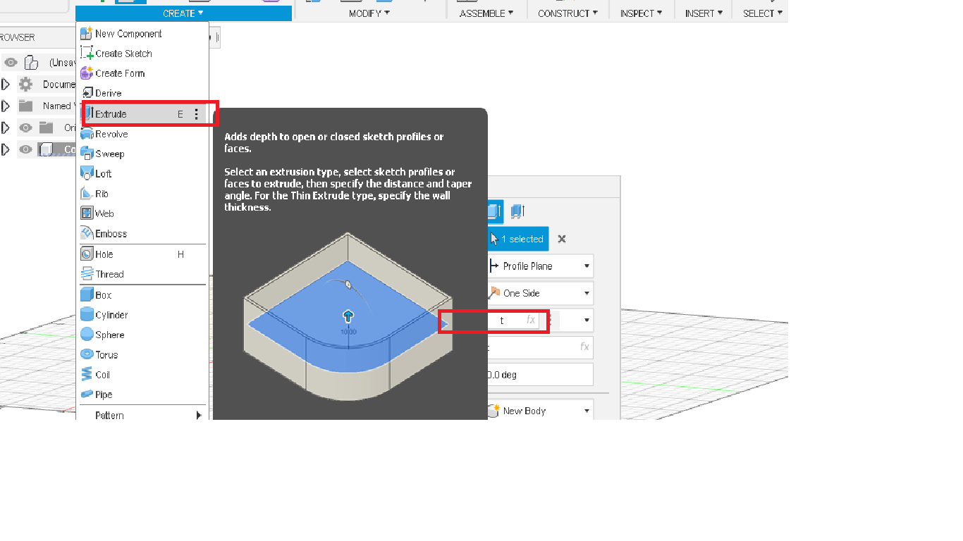
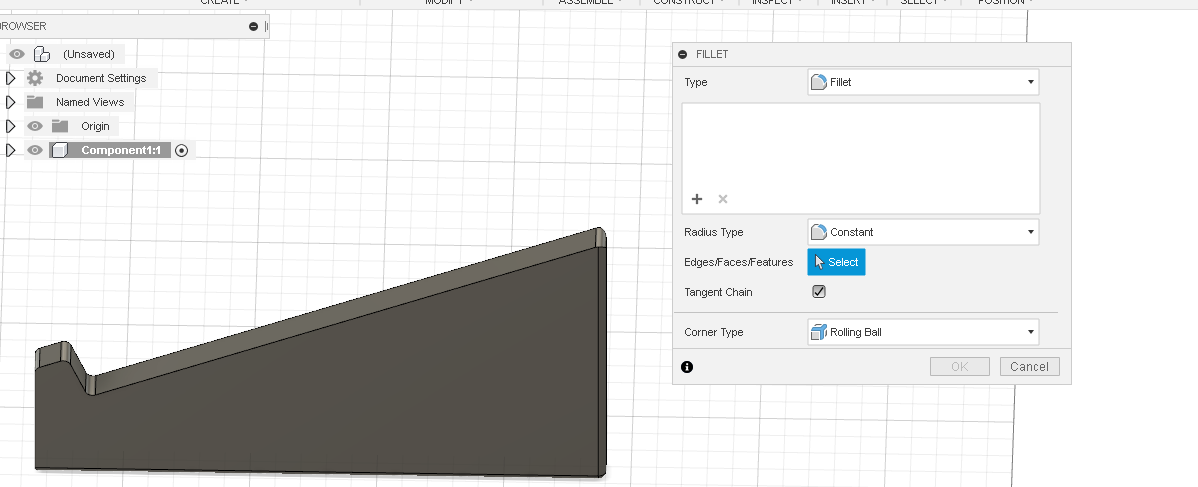
then I extruded the shape into the desired thikness and made sure to soften out the edges with 3mm fillet
\
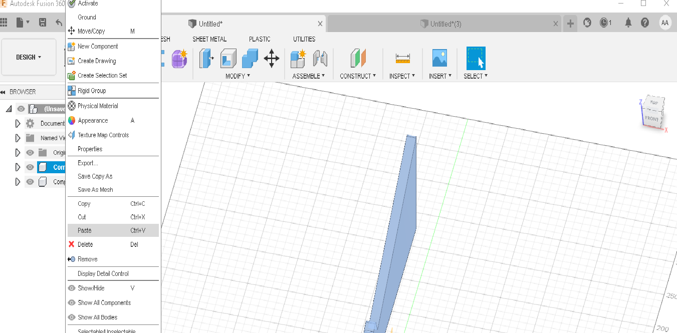
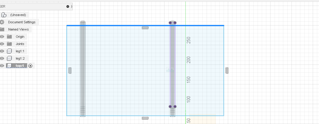
and to save time I copied one led and paste it in it , hence any thing I do in one leg , would occur in the other leg to , and then I used the joints tool and set the offset between the two legs to be 270mm which is almost equal to my sister laptop , note that the distance between the two legs is from the parametric table , hence it could be easily changed and customized to suits any laptop
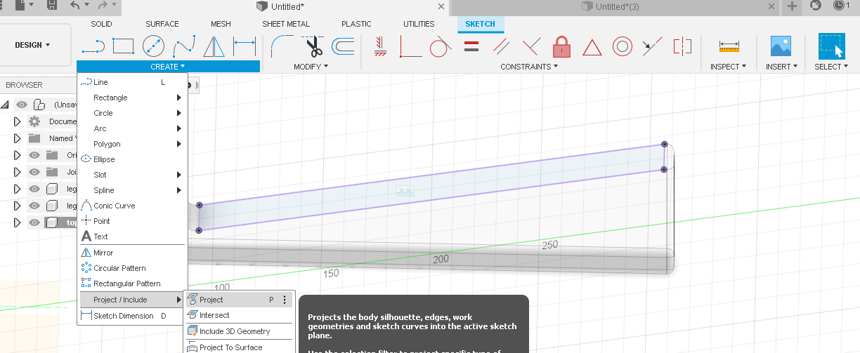
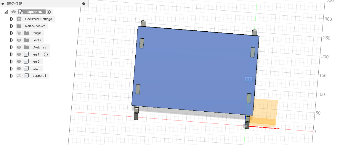
then I used the project table to project a new component in the legs which is the laptop top , and repeated the steps again (rough shape and then dimensions + constraints ) and add small rectangles and constrained them on the projected area and with the help of the mirror tools the result became like this after I extruded it
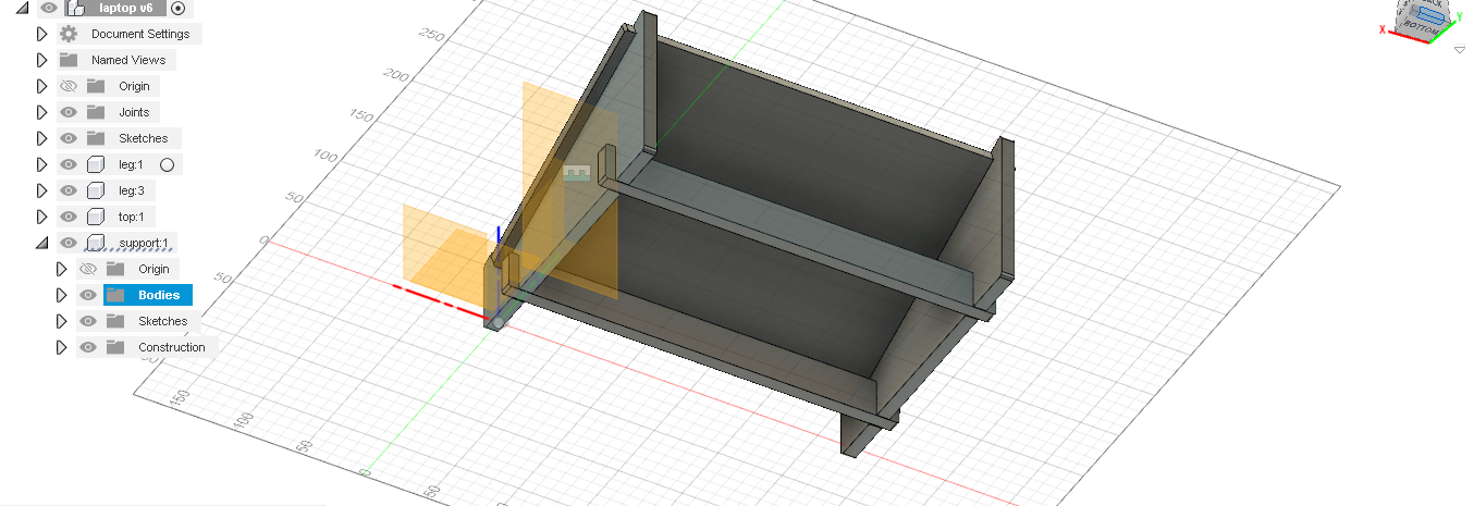
and lastly for the stand to not be wobbly , I added two supports , I designed one support with the process (rough shape then add dimensions and extruded it by negative t) and finally mirrored the support on mid-plane and the final result looked like this
Vcarve set up
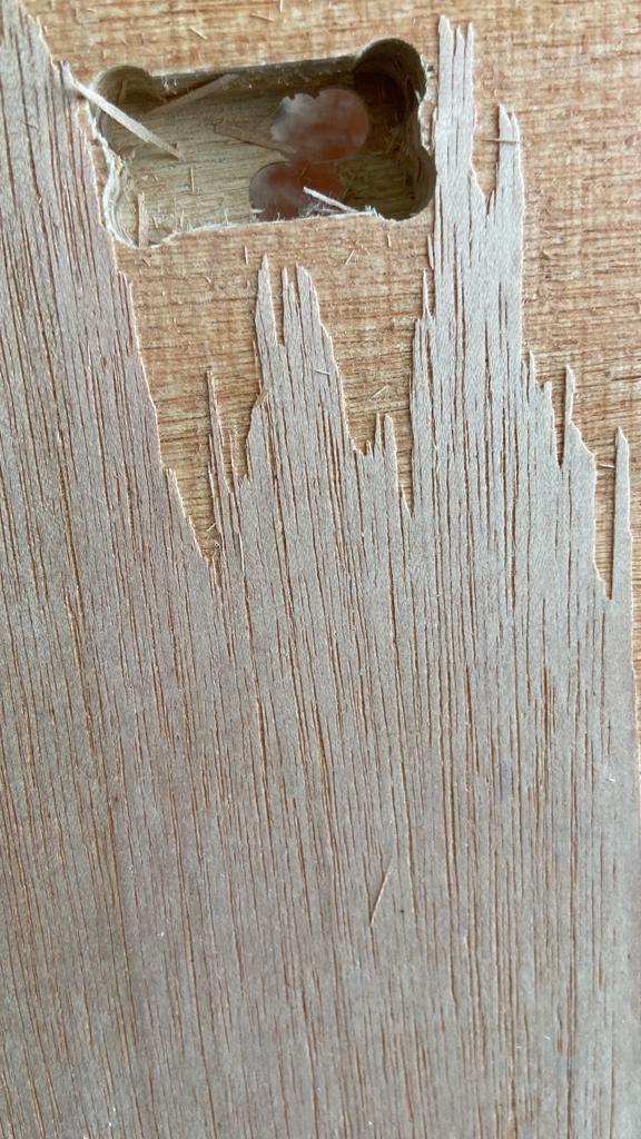
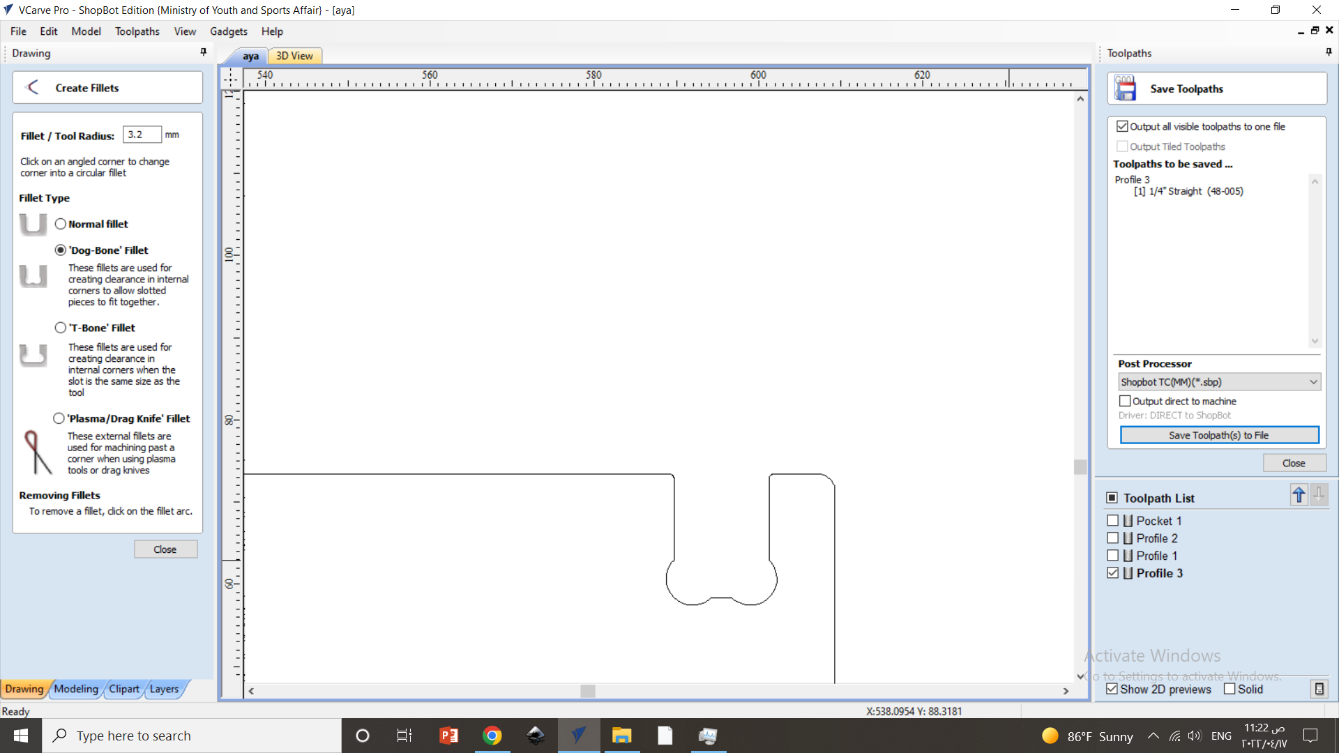
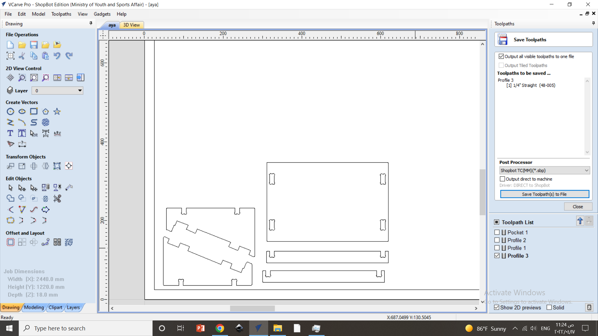
the first thing was to to set the fillets in dog-bone shape , to ensure that joints corner are been cut thoroughly and the diameter of the shape been set to 6 mm (3.2mm radius) same as the CNC needle diameter 6mm
after that all the dxf files been et together , and notice that unlike the laser cutter machine here you have to left enough space between the pieces.
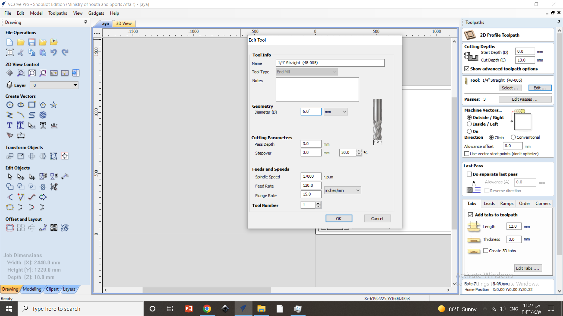
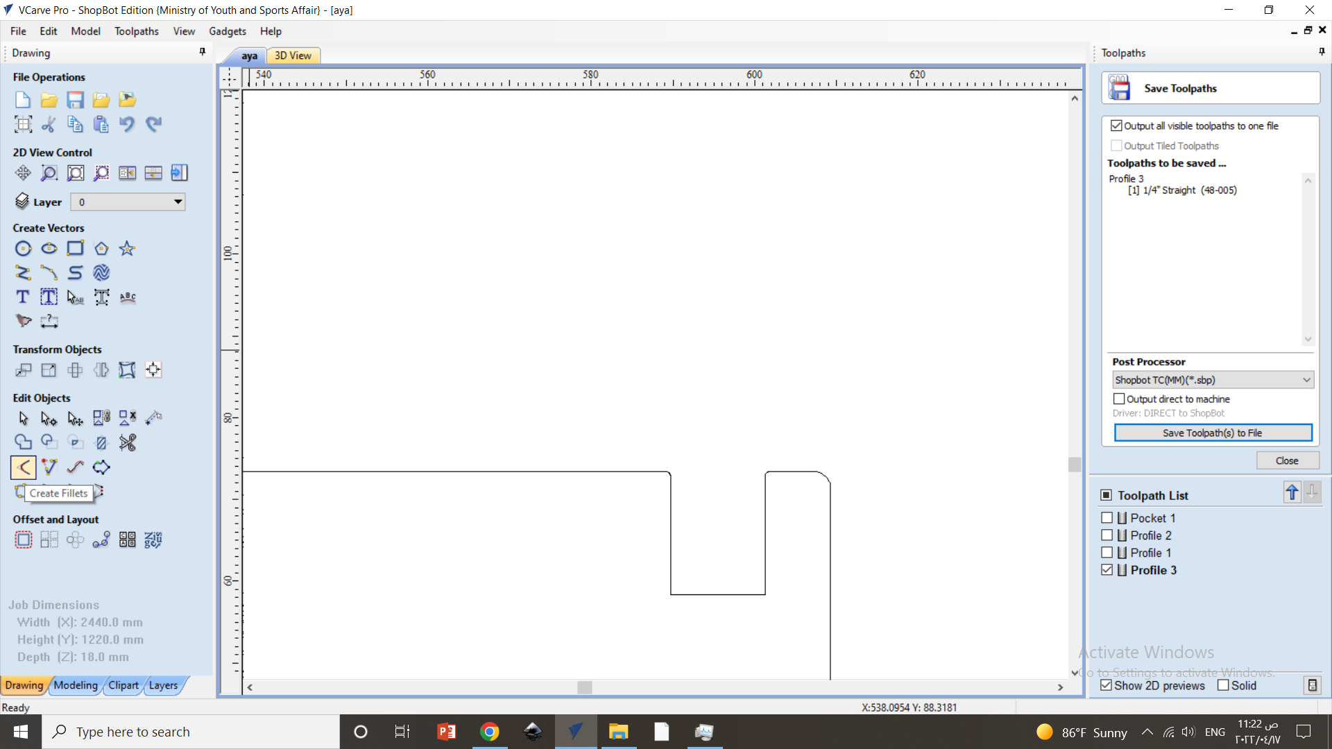
moving to the tool path , first you notice that the cut depth is set to be 13mm almost equal to the plywood thickness 12mm and the 1mm to ensure that the material been cut efficiently, after that the diameter of the needle been specified and the speed. note that the that there are two types of speed to specify rotational and normal one , the rotational is the number of spins per minute (Revolutions per minute) and the higher the r.p.m the stronger the cut gonna be, for plywood the standard r.p.m is 17000 , for harder materials the r.p.m is higher.
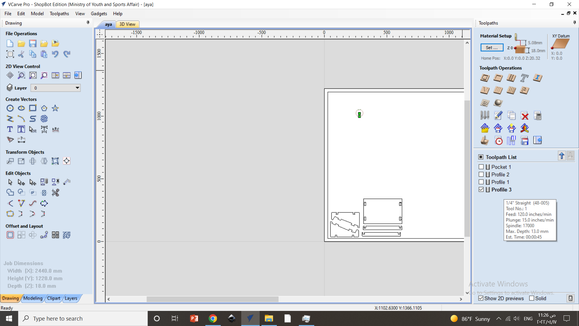
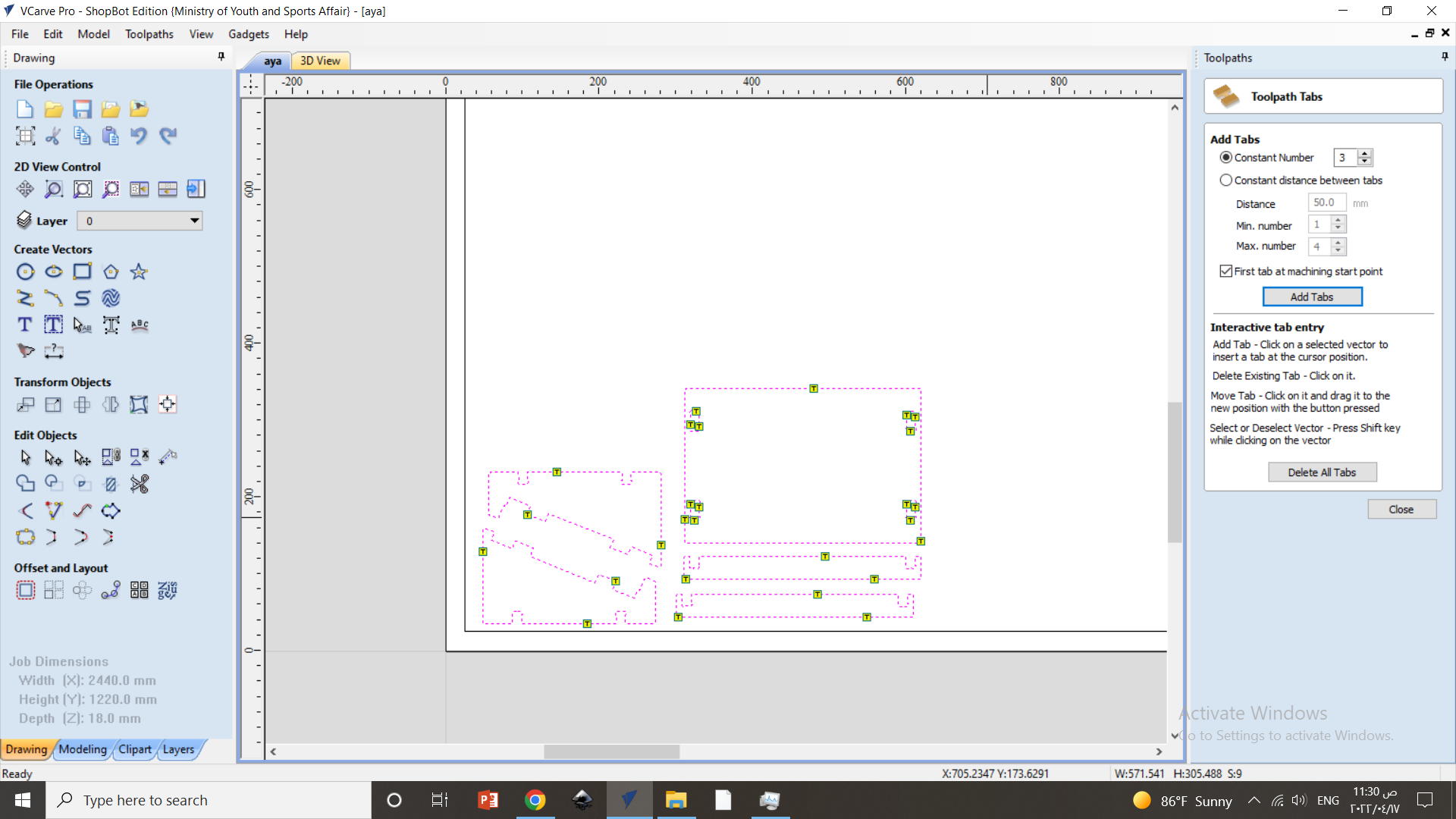
and the final step in tool path is to add tabs (3), the reason for that is to ensure that once the the pieces will intact in the plywood after they been cut.
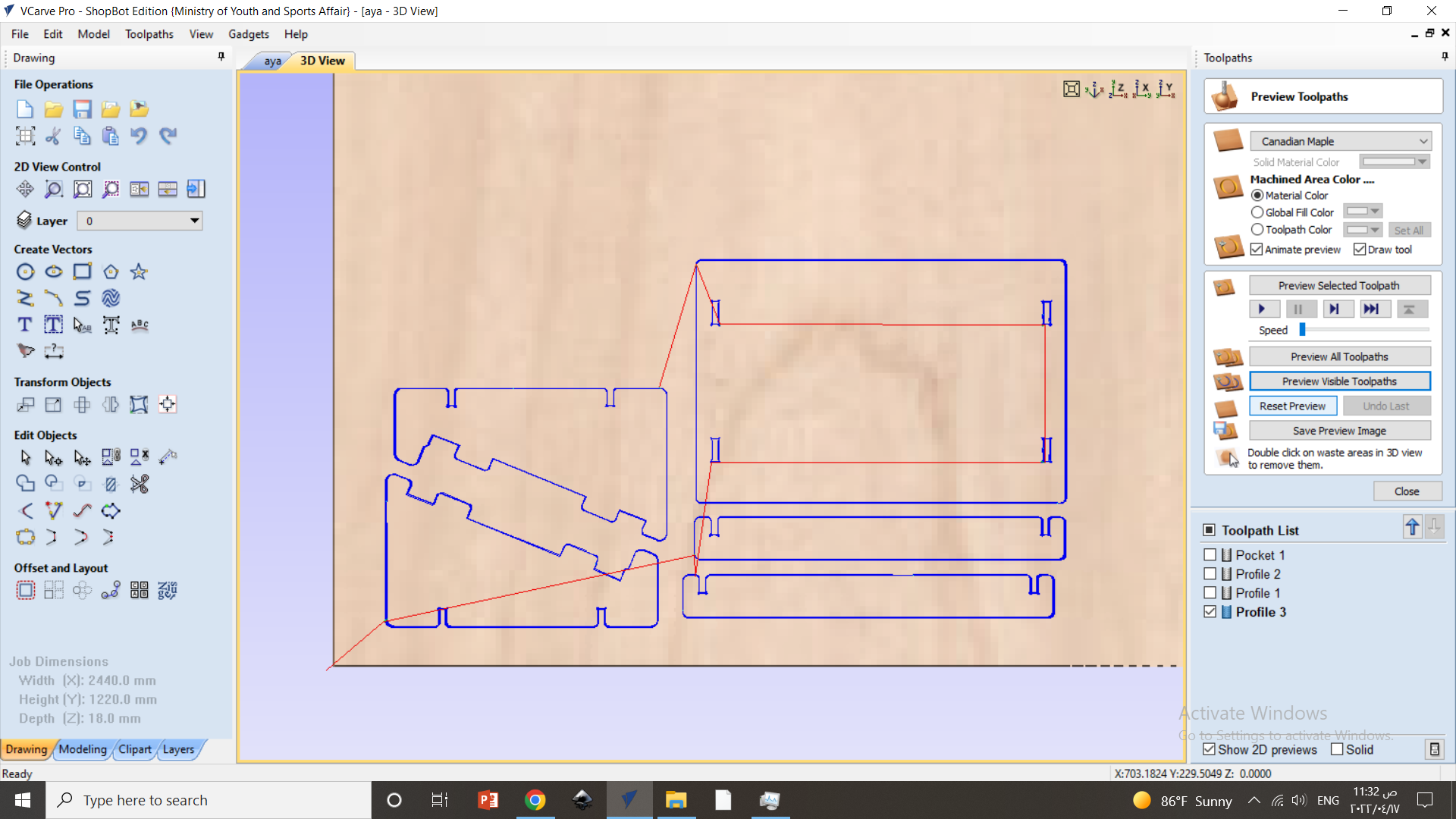
note that the red line indicates the path of the needle in the air
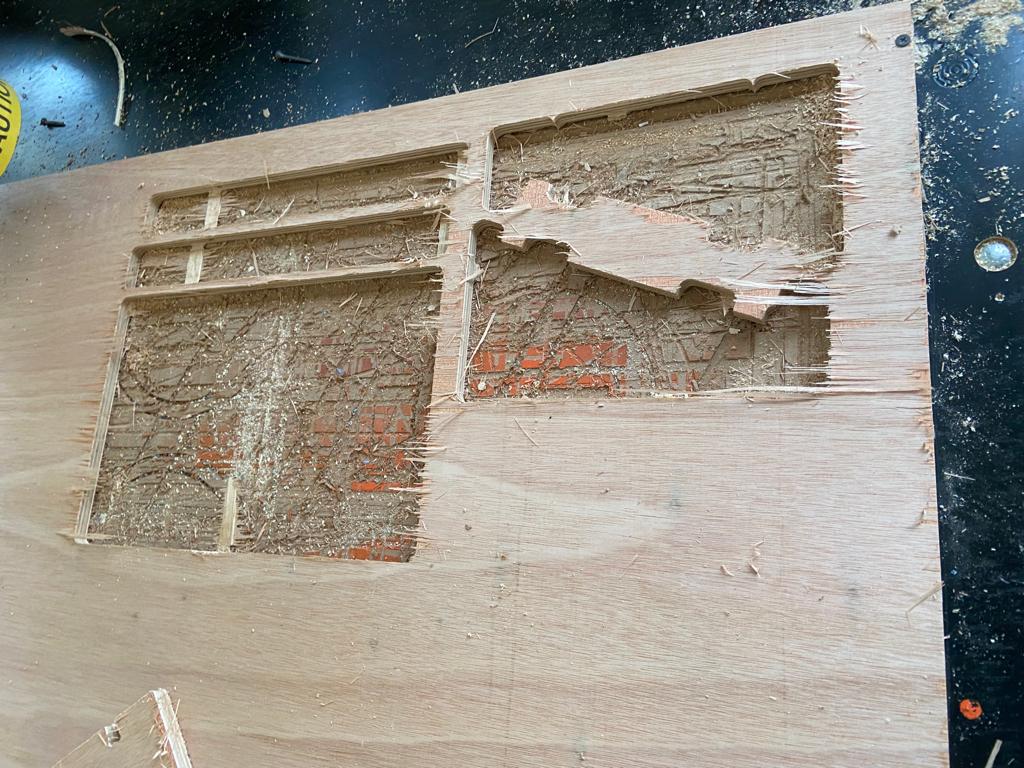
fabrication in cnc
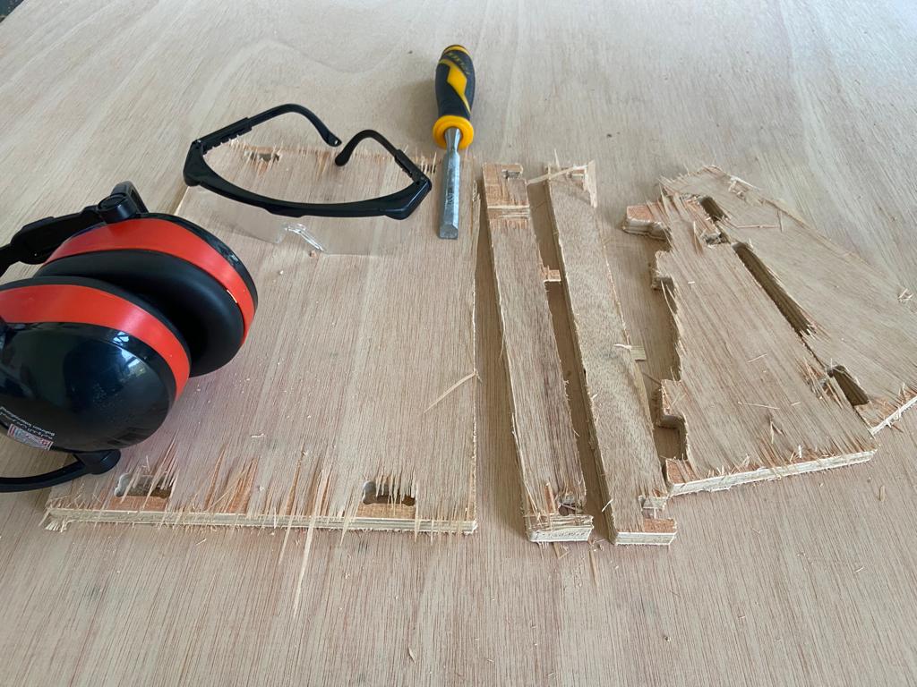
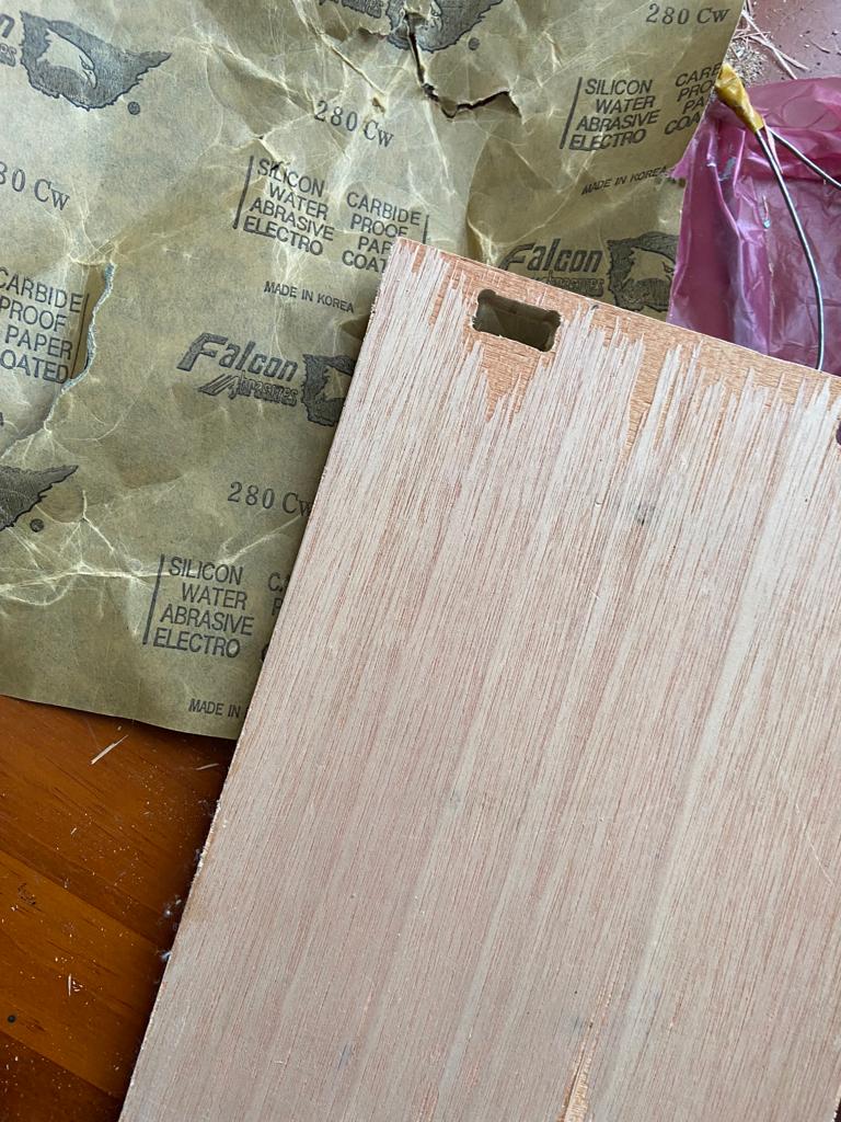
you can see obviously that the pieces needs some sanding to make it more neat and clean
and when I took them of I realized that there is some parts that need to be taken off from the joints
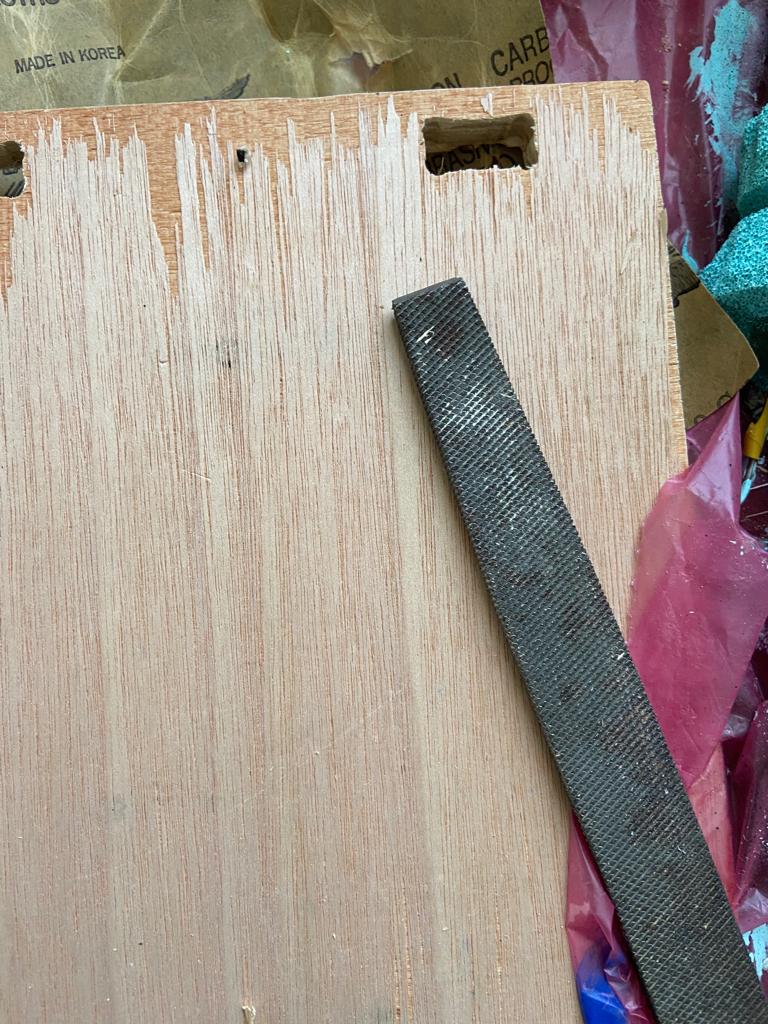
so I used this tool to sand and remove off these pieces
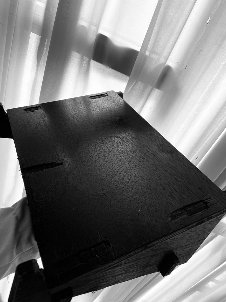
and for the assembling I used this hammer to bring the pieces together , and after spraying it with black paint the final result was like This , and the joy I saw in my sister face made me even more happy
>>
>>
design files