7. Input & Output device
This week I worked in input sensors, and output devices, connected to the Arduino MKR1010 microcontroller.
The difference between an input and output device
An input device sends information to a computer system for processing, and an output device reproduces or displays the results of that processing. Input devices only allow for input of data to a computer and output devices only receive the output of data from another device.
Pulse-width modulation (PWM)
PWM or Pulse Width Modulation is a technique used to control analog devices, using a digital signal. This technique can be used to output an analog-like signal from a digital device, like a microcontroller. We can control motors, lights, actuators, and more using the generated PWM signal. An important thing to note here is that PWM is not a true analog signal. The digital signal is modified in a way to fake an analog signal.
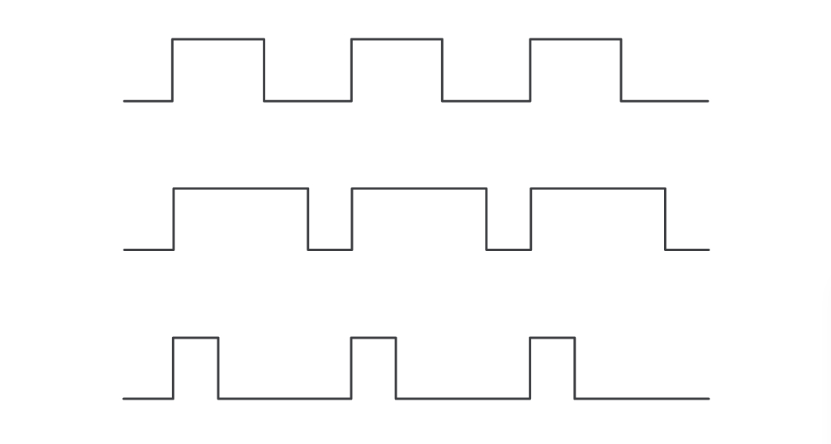 PWM Signal Waveforms
Task 1(DHT11 sensor)
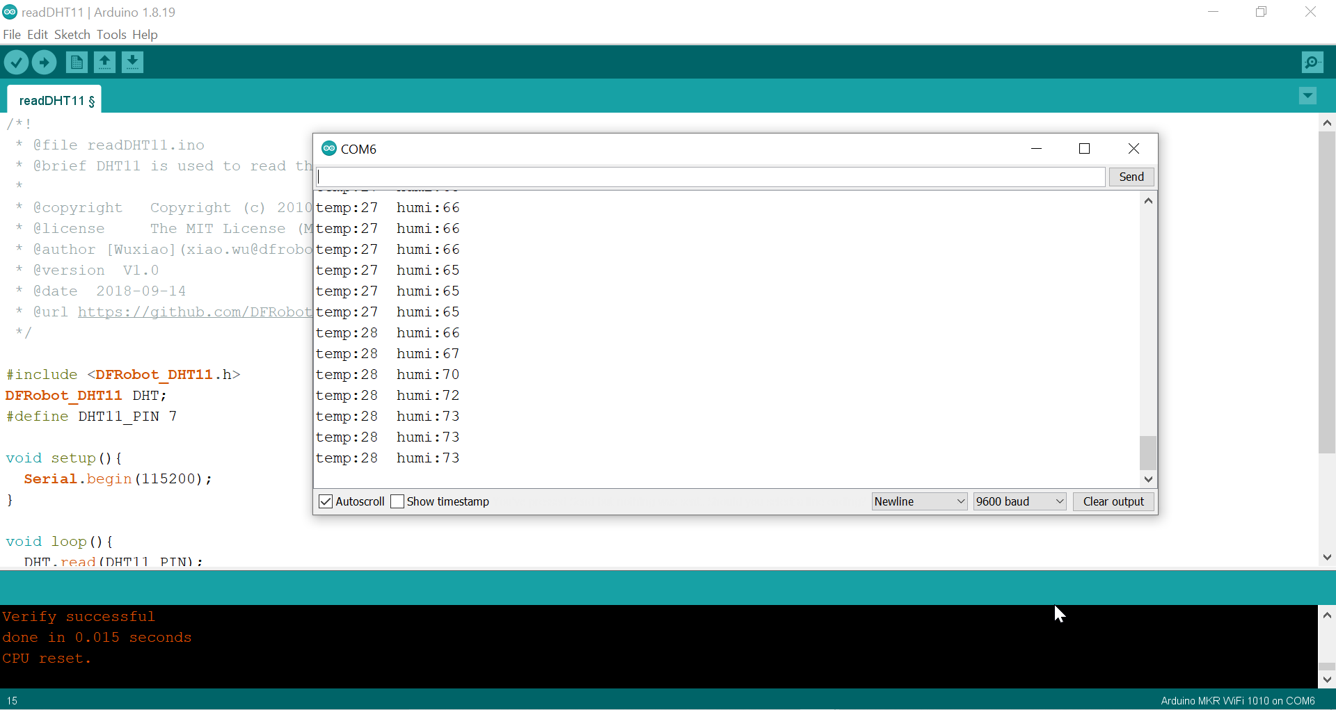
The DHT11 is a commonly used Temperature and humidity sensor that comes with a dedicated NTC to measure temperature and an 8-bit microcontroller to output the values of temperature and humidity as serial data.
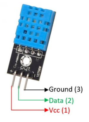
Steps of connection The sensor to microcontroller
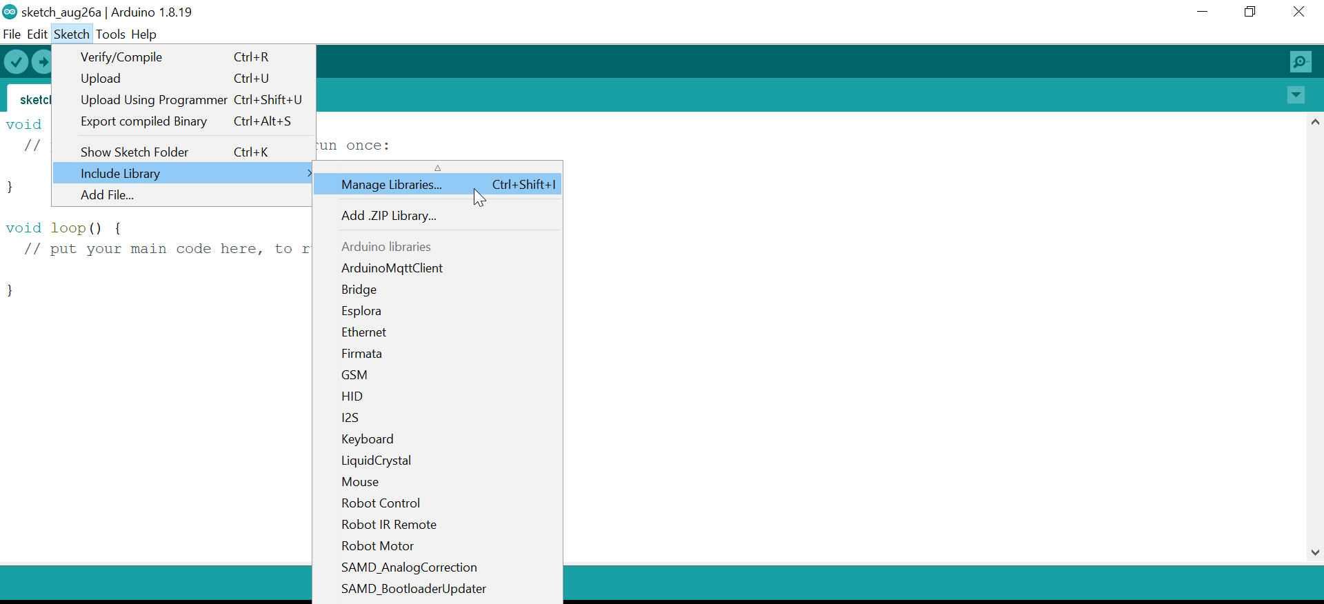
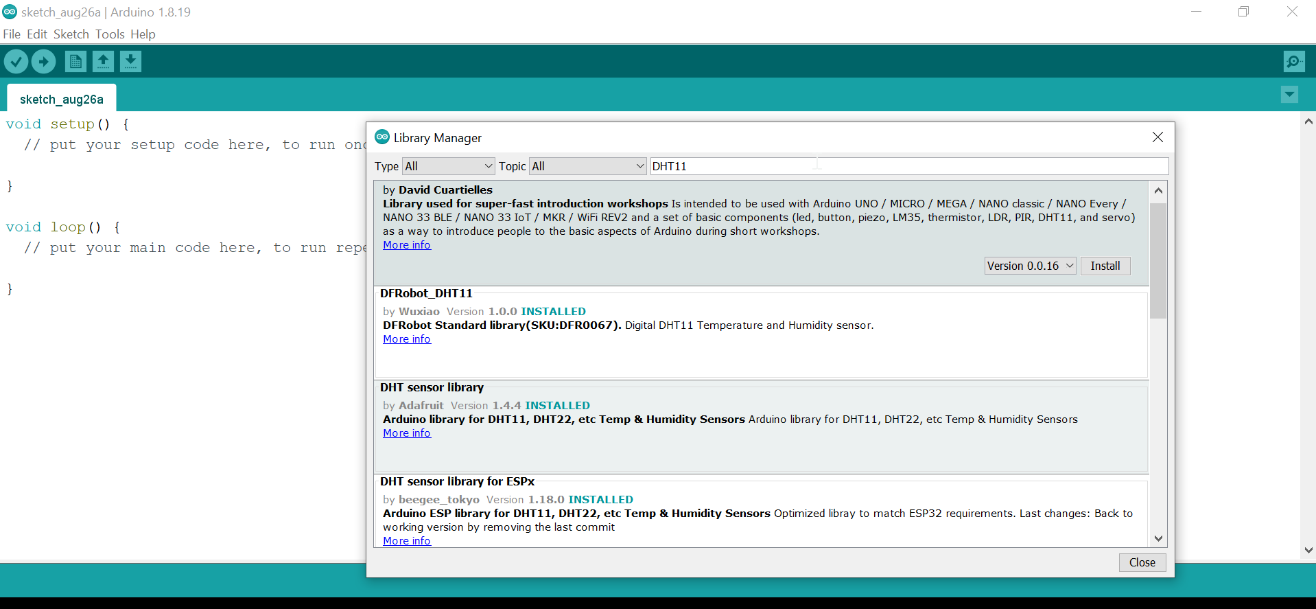
1.First open the Arduino and download the library of DHT11 sensor
Sketch>Include library>Manage libraries
2.Open the code from examples
#include <DFRobot_DHT11.h>
DFRobot_DHT11 DHT;
#define DHT11_PIN 7

void setup(){
  Serial.begin(115200);
}

void loop(){
  DHT.read(DHT11_PIN);
  Serial.print("temp:");
  Serial.print(DHT.temperature);
  Serial.print("  humi:");
  Serial.println(DHT.humidity);
  delay(1000);
}
The result
Task 2 (Servo motor)
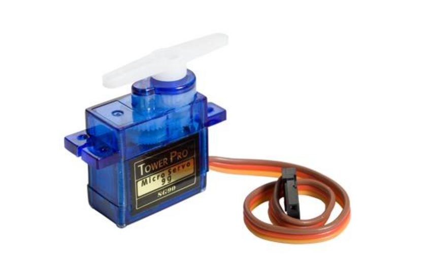
Servo motors have three wires: power, ground, and signal. The power wire is typically red, and should be connected to the 5V pin on the Arduino board. The ground wire is typically black or brown and should be connected to a ground pin on the board. The signal pin is typically yellow or orange and should be connected to PWM pin on the board. In these examples, it is pin number 9.
The code from examples
#include <Servo.h>

Servo myservo;  // create servo object to control a servo
// twelve servo objects can be created on most boards

int pos = 0;    // variable to store the servo position

void setup() {
  myservo.attach(9);  // attaches the servo on pin 9 to the servo object
}

void loop() {
  for (pos = 0; pos <= 180; pos += 1) { // goes from 0 degrees to 180 degrees
    // in steps of 1 degree
    myservo.write(pos);              // tell servo to go to position in variable 'pos'
    delay(15);                       // waits 15 ms for the servo to reach the position
  }
  for (pos = 180; pos >= 0; pos -= 1) { // goes from 180 degrees to 0 degrees
    myservo.write(pos);              // tell servo to go to position in variable 'pos'
    delay(15);                       // waits 15 ms for the servo to reach the position
  }
}
The result
Task 3 (DHT11 sensor with Servo motor)
I controlled the servo motor by tempreture using this code
#include<Servo.h>
Servo Myservo;
int pos;

#include "DHT.h"

#define DHTPIN 7     // Digital pin connected to the DHT sensor

#define DHTTYPE DHT11   // DHT 11

DHT dht(DHTPIN, DHTTYPE);

void setup() {
  Serial.begin(9600);
  Serial.println(F("DHTxx test!"));
  Myservo.attach(3);

  dht.begin();
}

void loop() {
  // Wait a few seconds between measurements.
  delay(2000);

  // Reading temperature or humidity takes about 250 milliseconds!
  // Sensor readings may also be up to 2 seconds 'old' (its a very slow sensor)
  float h = dht.readHumidity();
  // Read temperature as Celsius (the default)
  float t = dht.readTemperature();
  // Read temperature as Fahrenheit (isFahrenheit = true)
  float f = dht.readTemperature(true);

  // Check if any reads failed and exit early (to try again).
  if (isnan(h) || isnan(t) || isnan(f)) {
    Serial.println(F("Failed to read from DHT sensor!"));
    return;
  }

  // Compute heat index in Fahrenheit (the default)
  float hif = dht.computeHeatIndex(f, h);
  // Compute heat index in Celsius (isFahreheit = false)
  float hic = dht.computeHeatIndex(t, h, false);

  Serial.print(F(" Humidity: "));
  Serial.print(h);
  Serial.print(F("%  Temperature: "));
  Serial.print(t);
  Serial.print(F("C "));
  Serial.print(f);
  Serial.print(F("F  Heat index: "));
  Serial.print(hic);
  Serial.print(F("C "));
  Serial.print(hif);
  Serial.println(F("F"));

if(t>20){
  for(pos=0;pos<=180;pos++){
Myservo.write(pos);
delay(15);
}
  delay(1000);

  for(pos=180;pos>=0;pos--){
Myservo.write(pos);
delay(15);
}
  delay(1000);
}

}
The result
Task 4 (RGB color using KY009 sensor)
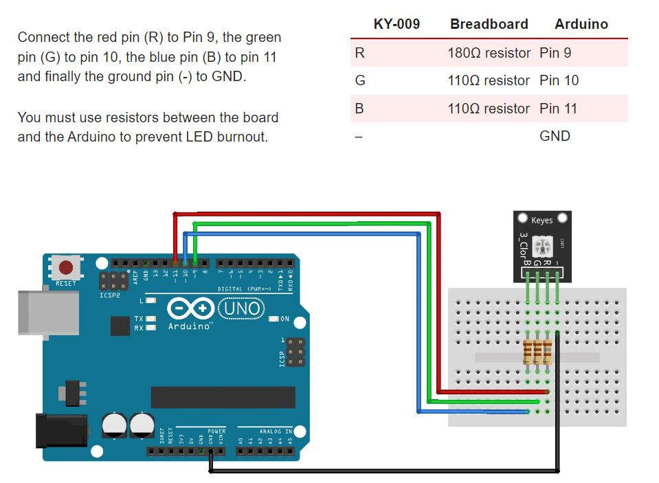
The KY-009 RGB Full Color LED module emits a range of colors by mixing red, green, and blue light. Each color is adjusted by using PWM.

The connection
The code
// Pins
#define BLUE 11
#define GREEN 10
#define RED 9
#define delayTime 10 // fading time
int MAX_LUM = 255;
int redVal,greenVal,blueVal;
void setup()
{
pinMode(RED, OUTPUT);
pinMode(GREEN, OUTPUT);
pinMode(BLUE, OUTPUT);
digitalWrite(RED, HIGH);
digitalWrite(GREEN, LOW);
digitalWrite(BLUE, LOW);
}
void loop()
{
redVal = MAX_LUM; // choose a Val between 1 and 255 to change the color.
greenVal = 0;
blueVal = 0;
for(int i = 0; i < MAX_LUM; i += 1) // fades out red bring green full when i=255
{
redVal -= 1;
greenVal += 1;
lightRGB(redVal, greenVal, blueVal);
delay(delayTime);
}
redVal = 0;
greenVal = MAX_LUM;
blueVal = 0;
for(int i = 0; i < MAX_LUM; i += 1) // fades out green bring blue full when i=255
{
greenVal -= 1;
blueVal += 1;
lightRGB(redVal, greenVal, blueVal);
delay(delayTime);
}
redVal = 0;
greenVal = 0;
blueVal = MAX_LUM;
for(int i = 0; i < MAX_LUM; i += 1) // fades out blue bring red full when i=255
{
// The following code has been rearranged to match the other two similar sections
blueVal -= 1;
redVal += 1;
lightRGB(redVal, greenVal, blueVal);
delay(delayTime);
}
}
void lightRGB(int r, int g, int b){
analogWrite(RED, r);
analogWrite(GREEN, g);
analogWrite(BLUE, b);
}
The result
Problems
My problem was in getting the KY-009 RGB to work. As the sensor we were using was a common anode sensor while we were following the connections for the common cathode sensor as it was labeled. So we fixed this problem by putting the ground pin in the Vcc pin instead.