4. Embedded programming
This week focuses more on the electrical side, and programming is also covered.
Microcontroller
An embedded system’s microcontroller is a small integrated circuit that controls a single process. On a single chip, a typical microcontroller has a CPU, memory, and input/output (I/O) peripherals.
Group Assignment
Evaluating the number of programming languages that can be utilized in a single microcontroller and how they compare.
Link to the comparison done by the whole Group
What have been learnt from reading a microcontroller data sheet
-
The Arduino Uno board has pins at the top and bottom where we may attach the inputs and outputs.
-
When connected to a computer, the board can receive power through the side-mounted pins.
- A widely used and standard microcontroller board is the Arduino Uno.
- A microcontroller can be linked to inputs and outputs, each having a particular set of specifications.
- The brain is often a black chip in the middle.
Individual Assignment
Arduino
I downloaded and installed the “Arduino IDE” software on my computer in order to program a microcontroller. Android IDE
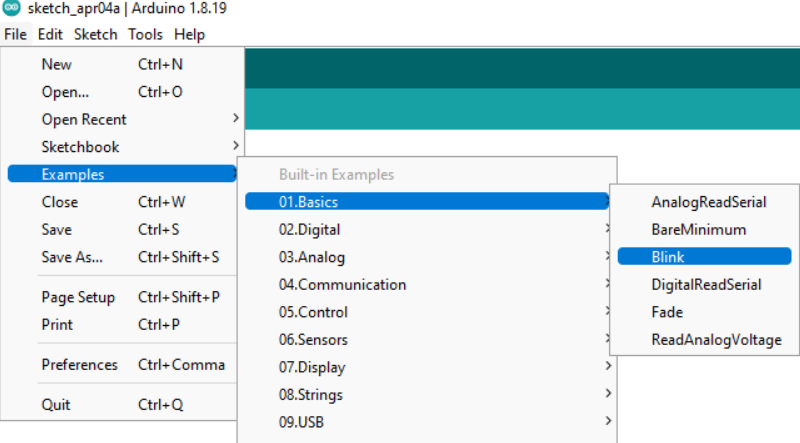
The image below depicts how the software’s workspace looks. The software’s format is displayed on the home screen. In the “void setup,” you first define the parameters of your work or programming. Second, you use the “void loop” command to input the code you wish to execute repeatedly in a loop. In between the curly brackets, you should place your code.

Numerous distinct templates are provided. I began by using the controller’s fundamental feature, which was the blink light.
To begin programming, I was handed an Adafruit microcontroller (nrf52840 feather). In accordance with the instructions on the page for setting up Arduino support, a Board Support Package was installed. The Adafruit controller may be programmed using this board library.
Copy the code from the aforementioned site, then put it in the Additional Boards Manager URL field under Files>Preferences. After installing the “Adafruit nrF52” and opening the boards manager from the “tools” menu, the Adafruit board is now visible.

I used a USB connection to connect my controller to the PC. Then choose the “Port” option for the specified controller under the “tools” menu.
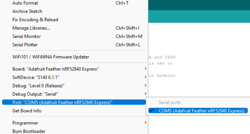
The words “High” and “Low” indicate that the light will turn on and off, accordingly. By using the command “Delay(time in milliseconds),” you may control how long it blinks. The LED was programmed to blink using the code below.

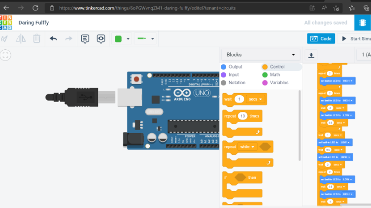
TinkerCad
Similar to the Arduino IDE, Tinkercad may be used to program electronics and then the type of microcontroller. You won’t find it if you use Adafruit, so use an Arduino instead because the coding is the same.

Then on tinkercad I used different codes to see it on the controller shown on the website including the light blink or the morse code I made.