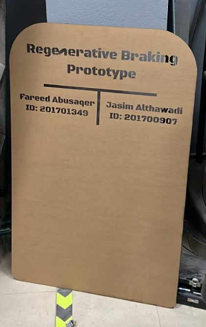
Final Project
More about the project can be found at my project partner’s website Jasim Althawadi Click Here to Visit Jasim’s Final project page
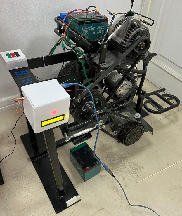
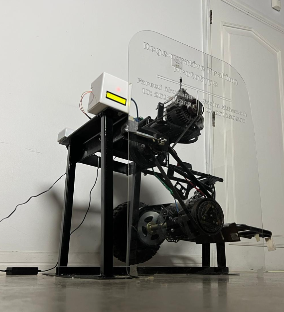
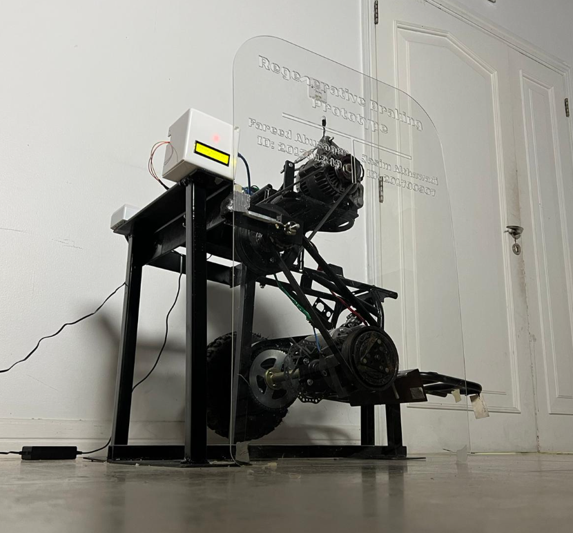
A regenerative braking prototype is to be designed using an Alternator, AC Compressor Clutch, Flywheel and Bicycle sprocket. Energy will be captured from braking showcasing the efficiency of the system. The prototype was built in both FABLAB Bahrain and Bahrain Polytechnic University in partnership with my colleague Jasim Althawadi. In FABLAB, an Acrylic display sheet was designed and laser cut.
A microcontroller with a small LED display was coded to measure the RPM of the flywheel used in the prototype, which was done using a magnet sensor that captures each time the magnet passes by the sensor in rotation. According to the first law of thermodynamics (energy conservation), “Energy cannot be generated or destroyed.” The prototype will be made to transform energy from one form to another by according to this law. By converting the kinetic energy in the drive shaft and wheel to heat energy that is dispersed in the environment without providing any advantage to the spread energy, the normal braking system for vehicles can lower the vehicle speed. Regenerative braking’s primary function is to recover some energy by converting kinetic energy to electric energy rather than transferring it completely to thermal energy.
Project’s Components
The prototype won’t be shrunk and will be made available for use in electric quads or any other hybrid/electric vehicles. For big vehicles, the design may be scaled up, or scaled down for smaller vehicles.
Electric Motor & shaft
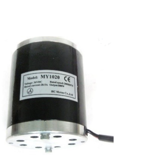 The system will be powered by an electric motor that has been chosen. where a lithium-Ion battery-powered 800W electric motor will be employed. The chosen motor has an RPM of 2800 and an 11-toothed tiny sprocket as the outlet connector.
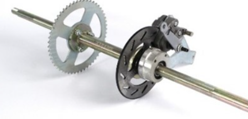 The driving shaft was chosen to be a rear electric quad shaft. The chosen shaft’s length of 560mm gives greater room to attach extra components to it if necessary. A sizable sprocket with 64 teeth is given with the drive shaft to link it to the motor, which will produce a powerful torque to propel the vehicle.
AC Compressor Clutch

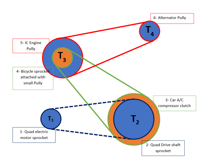
The A/C compressor clutch was chosen since it is simple to attach and disengage. The coil, pulley, and clutch are the three primary components of the A/C clutch. The coil is permanently attached to the compressor and is wired to the batteries. Over the coil, the pully is assembled and will spin freely over the compressor body. The clutch, which has a little gap between it and the pulley and is attached to the driving shaft, comes last. The pulley in the A/C compressor starts spinning when the engine starts, but the compressor is turned off by cutting the power to the coil. The coil will receive electricity when the drive turns on the air conditioning, creating a magnetic field that will allow the clutch to be attached to the pulley and operate the compressor. As a result of the clutch pulley’s 134.4mm diameter, speed may be increased.
Bicycle sprocket

The bicycle’s rear sprocket was chosen due to its mechanics. The fundamental function of the back sprocket is to rotate in one direction, while the shaft is unaffected by rotation in any other direction. Power will be transferred from the A/C clutch to the flywheel thanks to this characteristic of the sprocket (engine poly). In addition, if the drive shaft spins at a low RPM and the flywheel spins at a high RPM, the power from the flywheel will not transfer to the drive shaft when the system is turned on.
Alternator pulley
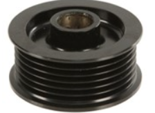
Since the clutch for the vehicle’s air conditioning system is a pully, an alternator pully was chosen to be coupled to the sprocket. This add-on will give you a bicycle sprocket mechanism and enable you to link the car’s A/C compressor clutch and the sprocket with a belt. The ability to raise speed is made possible by the alternator pulley’s 57.35mm diameter.
Bicycle shaft
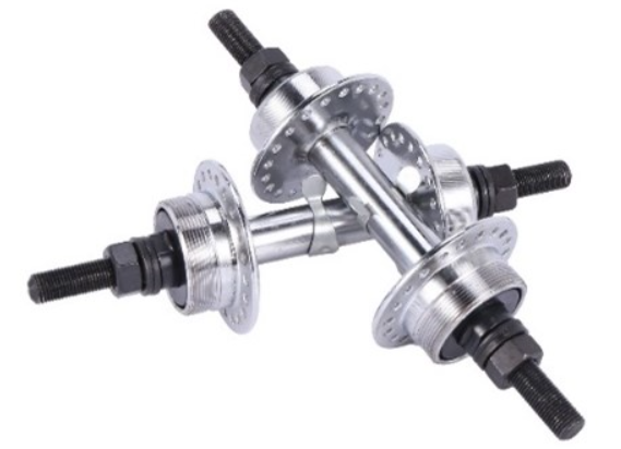
As the bicycle sprocket can be mounted to it simply by the thread portion, a bicycle rear axle was chosen to be the prototype. Additionally, the axel will include a shaft and bearing to link the shaft to the prototype body and to enable smooth rotation of the bearing with its sprocket and pulleys.
Engine pulley
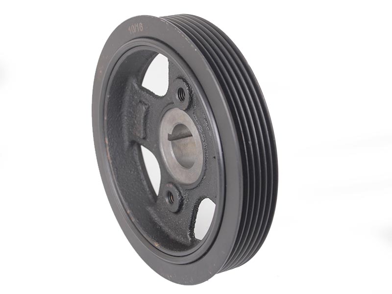
An engine pully was chosen because of its heavy weight and big diameter to be mounted on the same shaft as the bicycle sprocket. The engine pully’s heavy weight will enable it to save part of the available power while applying the brakes. Additionally, because the engine pully rotates at the same rate as a bicycle sprocket, the greater diameter will enable the following component to be given with a faster speed. The engine pulley’s diameter, which is 134.4 mm, will allow for an increase in speed.
alternator

The system’s supplied power was used to power an automobile alternator, which was chosen to create electricity. The alternator generates electricity by converting mechanical energy into electrical energy, which causes the rotor to begin rotating within the stator. Since the alternator requires stimulation to produce power, external electricity is required to start it. A light is attached to the alternator’s two terminals and the battery in order to test the alternator. While the alternator is stopped, the light will shine, but once it begins to spin and supply energy, the light will automatically turn off and the voltage will rise to charge the batteries. Because the pully on a vehicle alternator is smaller in diameter than the pully on an engine, it spins at a higher speed, which is necessary for the alternator to produce energy. The ability to raise speed is made possible by the alternator pulley’s 57.35mm diameter. The alternator must spin at roughly 2400 RPMs, hence an increase in speed is necessary.
Schematic
Below is the schematic of the prototype arrangement decided upon.
Manufacturing

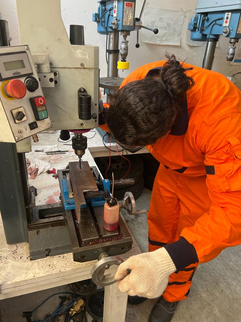
The manufacturing phase was done at the university and FabLab university where it went like this: 1. Cutting The chassis of the quad in half to use the rear one only.
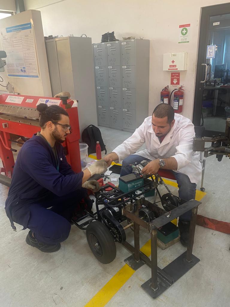
- Taking the necessary batteries and motor for the design.
- Cutting and welding a steel base for the prototype to sit on.
- Building a support steel base for the alternator, pulleys and AC compressor to be fixed on.
- Using tensioners multiple times to adjust the tension on the belts connecting the compressor to the flywheel and the bicycle sprocket to the Alternator.
- Testing the prototype with the power supply provided from a combination of Lithiom ion batteries and Lead Acid.
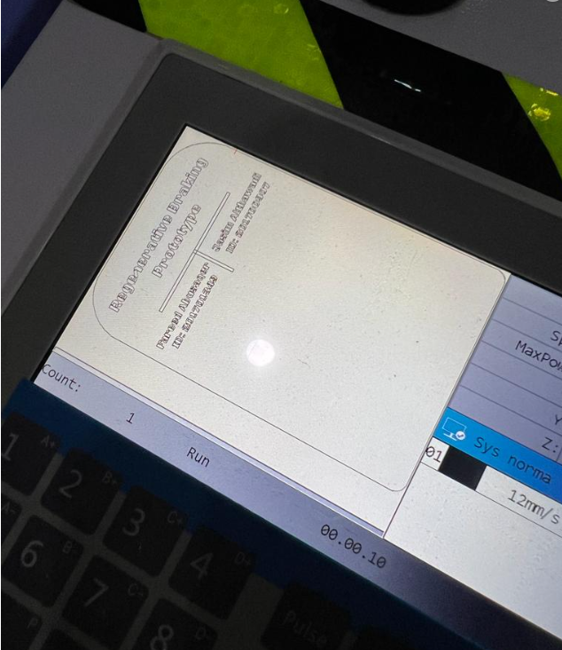
- Coding the Arduino with the magnet sensor and mini LED Screen that is going to be placed on the flywheel. for more information about how this was done visit this link
- Designing a box to cover the Arduino and display the LED screen in a more pleasant way.
- Testing the code and measuring the rpm on the display.
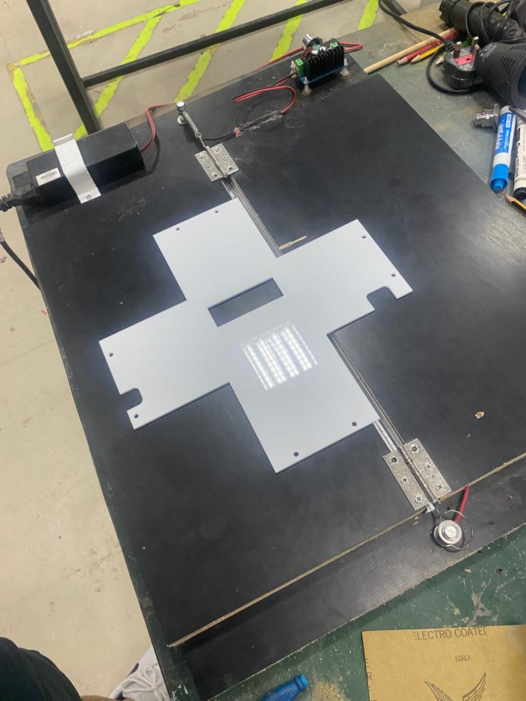
Acrylic Display sheet
The prototype was displayed at the Bahrain Polytechnic Recruitment Expo, and it was discovered that the belt side needs further protection. In order to safeguard anyone who approach the prototype to have a closer look, an acrylic sheet was made using a laser cutter. In order to offer the required protection and to display the names of the project group members, a design was created to cut the acrylic. Utilizing the largest size the laser cutter can cut, the pattern was created using the Inkscape program to cover the most possible space on the constructed side. The names were then delighted on the top of the protection once the dimension was set.

Controller & LED box
To cover up the microcontroller with its wiring connected to the LED Screen and power source, alongside protecting it from dust and external human interferences, an Acrylic box was designed in FUSION360 and laser cut after bending its sides with a heated wire.
Below is the design drawn in FUSION360 where the all holes where drawn to meet the fitting of the Arduino and the LED inside the box.

The design was then laser cut and placed on a heated wire as seen below to bend its edges that will make it turn into a box.

Box Hero Shot

Original FUSION360 design
Code used
Below is the code used to show the rpm of the flywheel on the mini LED Screen. The input was the magnet sensor recording each time the magnet passes through the sensor in rotation, while the output was the rpm value on the LED screen after taking the data for 60 seconds.
#include <SoftwareSerial.h>
#include <Wire.h>
#include <LiquidCrystal_I2C.h>

// Set the LCD address to 0x27 for a 16 chars and 2 line display
LiquidCrystal_I2C lcd(0x27, 16, 2);

const byte interruptPin = 2;
volatile byte countt = 0;
unsigned long startTime;
unsigned long actualstartTime;
bool started = false;
bool actualstarted = false;
int rpm = 0;


void setup() {
  Serial.begin(9600);
  pinMode(interruptPin, INPUT);
  attachInterrupt(digitalPinToInterrupt(interruptPin), blink, RISING);
  // initialize the LCD
  lcd.begin();

  // Turn on the blacklight and print a message.
  lcd.backlight();
}

void loop() {
  Serial.println(countt);
  Serial.println(millis());
  if (countt==1 && started == false ){
    startTime = millis();
    Serial.println("two second start");
    started = true;
  }
  if (millis() - startTime > 2000 && started == true && actualstarted == false ){
    actualstartTime = millis();
    Serial.println(countt);
    Serial.println("real  time started");
    actualstarted = true;
    countt = 0;
    startTime = 0;
  }
  if (millis() - actualstartTime > 6000 && actualstarted == true ){
    Serial.println("6 seconds passed");
    //actualstarted = true;
    rpm = countt * 10;
    countt = 0;
    actualstartTime = millis();

   lcd.clear();
   lcd.setCursor(0,0);
   lcd.print("Engine Pulley RPM");

   lcd.setCursor(6,1);
   lcd.print(rpm);
  }

  Serial.println("-------------------------");
  Serial.print("rpm");
  Serial.println(rpm);
}

void blink() {
  countt = countt + 1;
}
Final Project Hero Shots: -