7. Input & Output device
I spent this last week working on the input and output devices. when it is used to portray or regulate a certain motion or movement. The action you want the sensor or device to do is known as the input, and the action that the sensor actually produces is known as the output. There are several examples of input and output systems that may be found, seen, and utilized in daily life. For instance, a sensor programmed to unlock a lock when the right password is written will do so after the proper password is entered. The projects below were created in order to learn more and get more information on the input and output system: -.
RPM Indicator
After producing and testing regenerative braking, the concept for a sensor to measure the rotational speed of a pulley emerged. The pulley connects the automobile AC clutch to the alternator and is mounted on the final project (Regenerative Braking System). To complete this project, two tests were undertaken, and the results are shown below:-
Limit Switch (first test)
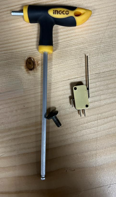
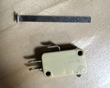
Using a Limit switch is the first suggestion for counting the rotation of the pulley. A limit switch may be triggered by the motion of a machine component or the presence of an object. A limit switch can be used to run machinery as part of a control system, as a safety interlock, or as a counter to keep track of items that cross a certain point. When the engine pulley completes one full rotation, a bolt that was used to activate the switch will press the limit switch. The limit switch, alinkey, and bolt used to make the first test are shown in the image below:
The pulley that the test will made on it:-
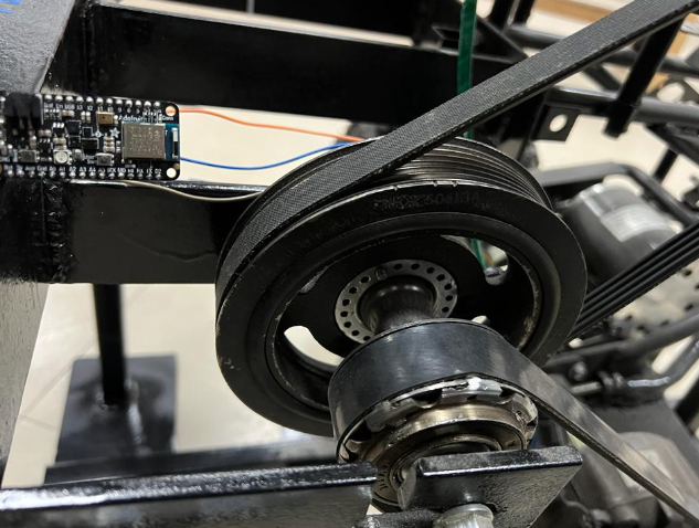
The limit switch was attached to the microcontroller that would be programmed to count the RPM after the components had been fixed to the prototype.

The limit switch broke after starting the motor and reaching a high speed, therefore we had to devise another way to determine the RPM:
Magnetic field sensor (Second Test)
A magnetic sensor was employed for the second test, which can count the RPM when a magnet comes close by. A magnet was mounted to the engine pulley while the sensor was fastened into the pulley stand to conduct the test. The magnet was fixed using two layers of double-sided tape in order to ensure that it was close enough to be noticed by the sensor once the sensor had been properly installed.
The sensor’s goal is to measure the engine pulley’s RPM by keeping track of each time it completes a full rotation. When we run the test, it turns out that the sensor counts up to 254 rotations before starting over at zero. Because of this, the RPM count is calculated by counting the rotations in 6 seconds, then multiplying that number by 10 to get the number of rotations in one minute. Additionally, it is discovered that the regenerative braking system reaches its maximum speed two seconds after it is turned on; as a result, calculations begin two seconds after the initial spin.
#include <SoftwareSerial.h>

const byte interruptPin = 5;
volatile byte countt = 0;
unsigned long startTime;
unsigned long actualstartTime;
bool started = false;
bool actualstarted = false;


void setup() {
  Serial.begin(9600);
  pinMode(interruptPin, INPUT);
  attachInterrupt(digitalPinToInterrupt(interruptPin), blink, RISING);
}

void loop() {
  Serial.println(countt);
  Serial.println(millis());
  if (countt==1 && started == false ){
    startTime = millis();
    Serial.println("two second start");
    started = true;
  }
  if (millis() - startTime > 2000 && started == true && actualstarted == false ){
    actualstartTime = millis();
    Serial.println(countt);
    Serial.println("real  time started");
    actualstarted = true;
    countt = 0;
  }
  if (millis() - actualstartTime > 6000 && actualstarted == true ){
    Serial.println("6 seconds passed");
    actualstarted = true;
  }
}

void blink() {
  countt = countt + 1;
}
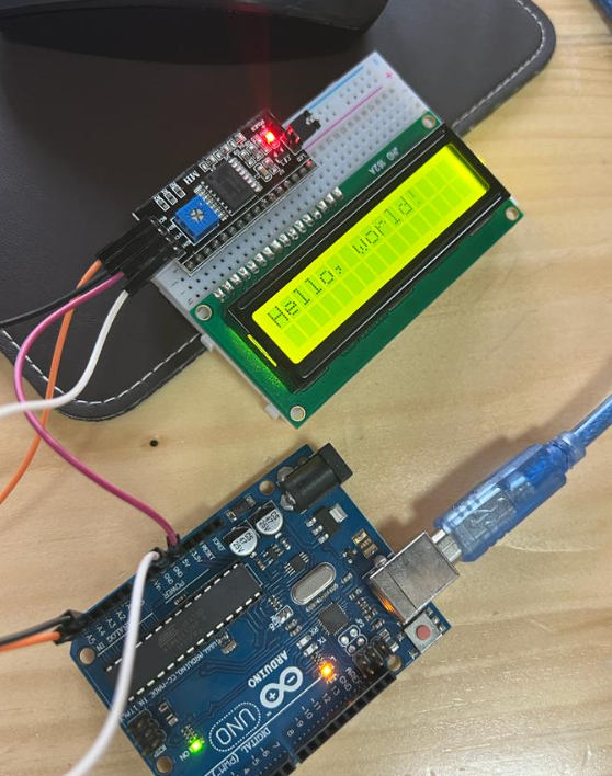
Once the sensore has produced an acceptable result, it is time to begin programming an LCD panel to display the engine pulley RPM. In order to learn how to code the LCD panel, considerable study was done. The LCD was tested by printing (Hello, world) on the LCD screen using the following commands.
#include <Wire.h>
#include <LiquidCrystal_I2C.h>

// Set the LCD address to 0x27 for a 16 chars and 2 line display
LiquidCrystal_I2C lcd(0x27, 16, 2);

void setup()
{
    // initialize the LCD
    lcd.begin();

    // Turn on the blacklight and print a message.
    lcd.backlight();

}

void loop()
{
  lcd.clear();
    lcd.print("Hello, world!");
 delay (1000);
 lcd.clear();
 lcd.print("hh!");
 delay (1000);
}
While we were confident that the code was valid at first, the LCD screen was initially blank. We discovered that the LCD backdrop light is extremely high after inspecting the cables and the LCD screen, and as we turned the light down, the words began to appear.
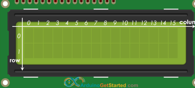
The code was transferred to the original code that was used to operate the sensore after the screen and the code had been tested. The sentence “Hello, world” was modified to include the computed RPM. The screen displaying a word on the first line and the RPM on the second line is one of the challenges encountered during this process. As a result, considerable study was done to determine how to deliver the sentence and the RPM in the desired manner. The LCD panel was discovered to be divided into two rows and 16 columns, and by locating the following image, it was simple to choose the precise location to exhibit the sentences and the RPM:
The final code used for the LCD panel, where all necessary sentences and the RPM are maintained in the proper location, is as follows: -
#include <SoftwareSerial.h>
#include <Wire.h>
#include <LiquidCrystal_I2C.h>

// Set the LCD address to 0x27 for a 16 chars and 2 line display
LiquidCrystal_I2C lcd(0x27, 16, 2);

const byte interruptPin = 2;
volatile byte countt = 0;
unsigned long startTime;
unsigned long actualstartTime;
bool started = false;
bool actualstarted = false;
int rpm = 0;


void setup() {
  Serial.begin(9600);
  pinMode(interruptPin, INPUT);
  attachInterrupt(digitalPinToInterrupt(interruptPin), blink, RISING);
  // initialize the LCD
  lcd.begin();

  // Turn on the blacklight and print a message.
  lcd.backlight();
}

void loop() {
  Serial.println(countt);
  Serial.println(millis());
  if (countt==1 && started == false ){
    startTime = millis();
    Serial.println("two second start");
    started = true;
  }
  if (millis() - startTime > 2000 && started == true && actualstarted == false ){
    actualstartTime = millis();
    Serial.println(countt);
    Serial.println("real  time started");
    actualstarted = true;
    countt = 0;
    startTime = 0;
  }
  if (millis() - actualstartTime > 6000 && actualstarted == true ){
    Serial.println("6 seconds passed");
    //actualstarted = true;
    rpm = countt * 10;
    countt = 0;
    actualstartTime = millis();

   lcd.clear();
   lcd.setCursor(0,0);
   lcd.print("Engine Pulley RPM");

   lcd.setCursor(6,1);
   lcd.print(rpm);
  }

  Serial.println("-------------------------");
  Serial.print("rpm");
  Serial.println(rpm);
}

void blink() {
  countt = countt + 1;
}
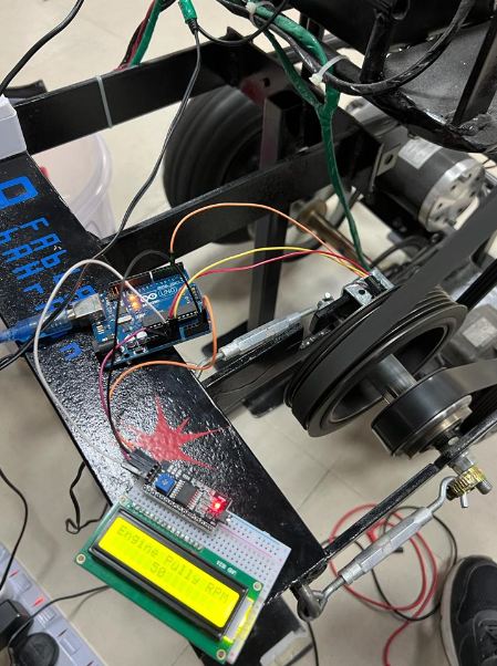
The following photo present the LCD screen after uploading the code to the microcontroller:-

After setting the proper codes, the prototype was tested once again to confirm that the sensor’s given RPM was accurate. The given RPM was not constant like when we first tested it; instead, the screen displayed a fluctuating RPM, as seen in the photographs below:-
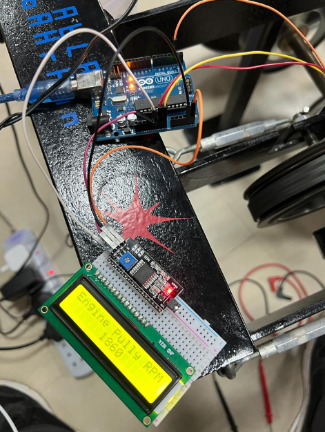
A double check was done in order to identify the issue since, on one actual time RPM, it indicated that the RPM was 50RPM, then it displayed 1860, and the number kept shifting with significant variations. It is discovered that the pulley speed fluctuates together with the engine’s sound on a will. When the battery became very low and the clutch could not be linked to the pulley very well, it was discovered that the car’s AC clutch was to blame for these alterations. This issue was fixed by keeping the battery charged so it would function properly during the final test.