5. Embedded programming
This week I learnt about microcontrollers and how they work.
Microcontroller
A microcontroller is a compact integrated circuit designed to govern a specific operation in an embedded systems like displaying microwave’s information, receiving remote signals, etc. The general microcontroller consists of the processor, the memory (RAM, ROM, EPROM), Serial ports, peripherals (timers, counters), etc.
Group Assignment
Our group assignment was to read about the microcontroller, also the datasheet for the microcontroller board we are programming.
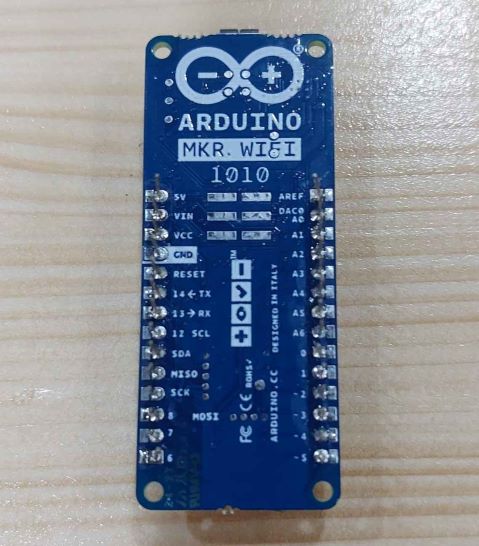
Arduino MKR Wifi 1010
The Arduino MKR WiFi 1010 is a great choice for any beginner, maker or professional to get started with Internet of Things (IoT). Using the popular Arm® Cortex®-M0 32-bit SAMD21 processor, it also features the ECC508 crypto-chip for security. The board is part of the MKR family, where you can choose from a large variety of shields to build projects out of the box with minimal effort! MKR 1010 simplifies the prototyping of WiFi-based IoT applications, easily connected and configured to other Arduino products. You do not need to be a network expert! The hybrid WiFi / BLE connectivity module has a low power consumption mode, improving the life of your batteries. It is Ideal for building wireless sensor networks in minutes and for remotely operated devices. The board can connect to any kind of existing WiFi network, or use it to create your own Arduino Access Point. It is also possible to connect your board to different Cloud services, including Arduino IoT cloud! Simply to power with a USB cable or external Li-Po 3.7V battery. Recharge the battery through the USB port.
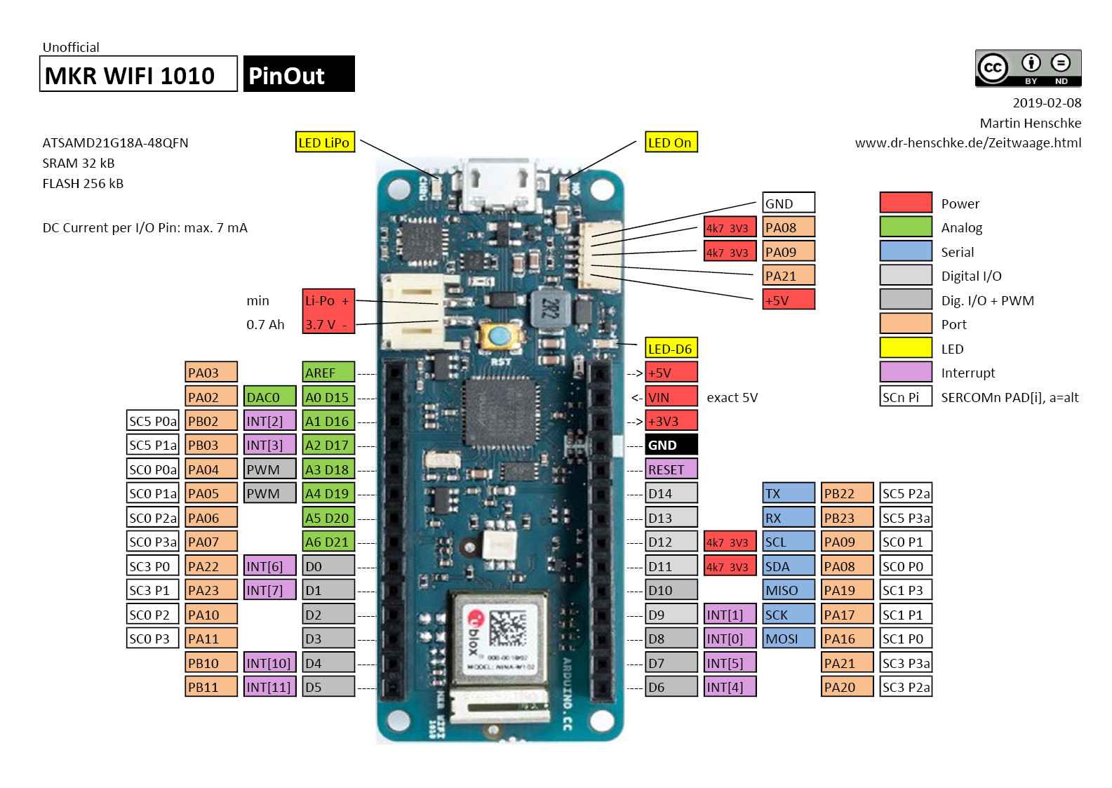
Arduino MKR Wifi 1010 datasheet
Remarks
After reading the datasheet of the Arduino MKR Wifi, I got to know about the specifications of the Arduino MKR Wifi. Most importantly, I learned about its pins, which will be extremely useful in completing my tasks. I got to know about the pins functions, e.g., which pin is analog and which pin is digital and which pins are PWM. Analog pins can be connected to analog sensors, and digital pins can be connected to digital inputs and outputs. PWM stands for Pulse Width Modulation and it is a technique used in controlling the brightness of LED, speed control of DC motor, controlling a servo motor or where you have to get analog output with digital means. The PWM pins are labeled with ~ sign on Arduino MKR Wifi. This information about pins will also be very useful for input and output assignment tasks.
Individual Work
Arduino IDE
The Arduino IDE software (Arduino Integrated Development Environment software) contains a text editor for writing code, a message area, a text console, a toolbar with buttons for common functions and a series of menus. It connects to the Arduino hardware to upload programs and communicate with them. The open-source Arduino Software (IDE) makes it easy to write code and upload it to the board. This software can be used with any Arduino board.
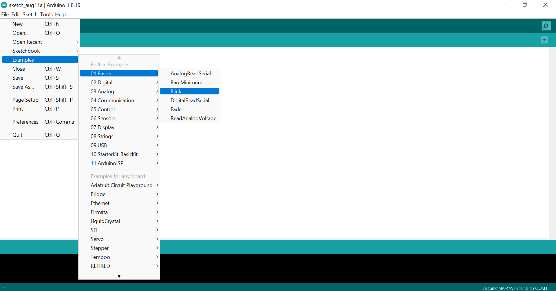
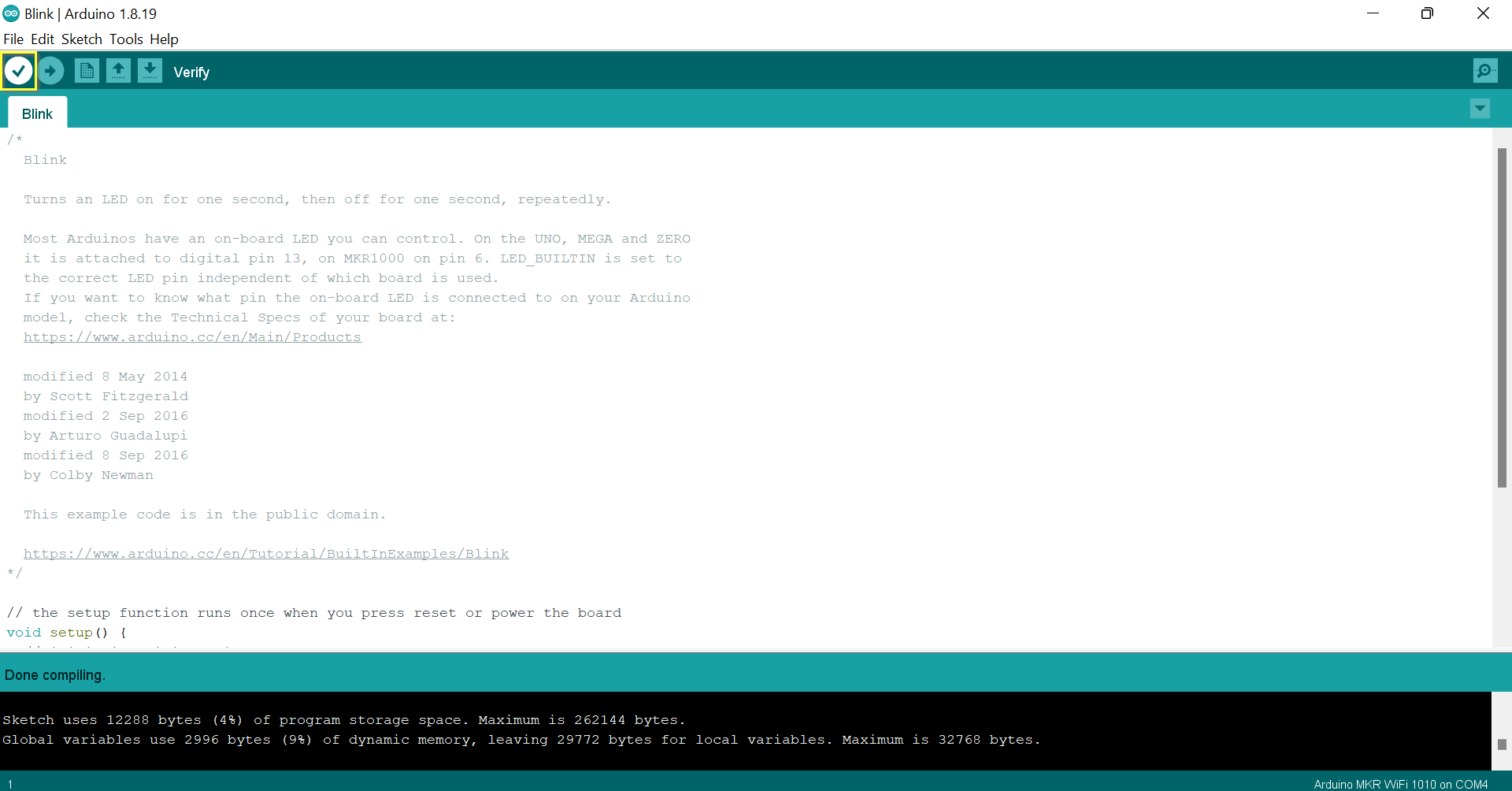
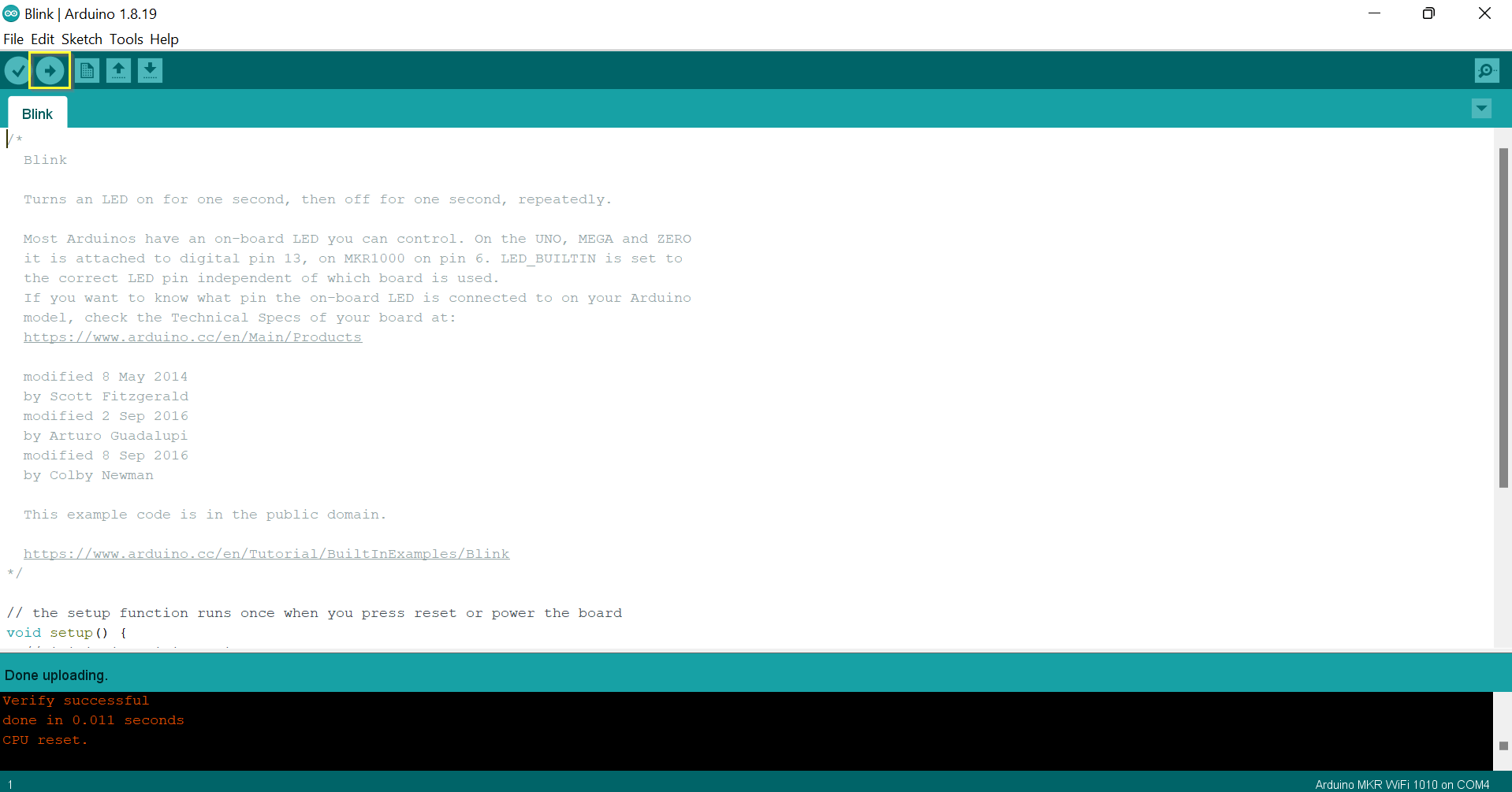
Blink Example
// the setup function runs once when you press reset or power the board
void setup() {
  // initialize digital pin LED_BUILTIN as an output.
  pinMode(LED_BUILTIN, OUTPUT);
}

// the loop function runs over and over again forever
void loop() {
  digitalWrite(LED_BUILTIN, HIGH);   // turn the LED on (HIGH is the voltage level)
  delay(1000);                       // wait for a second
  digitalWrite(LED_BUILTIN, LOW);    // turn the LED off by making the voltage LOW
  delay(1000);                       // wait for a second
}
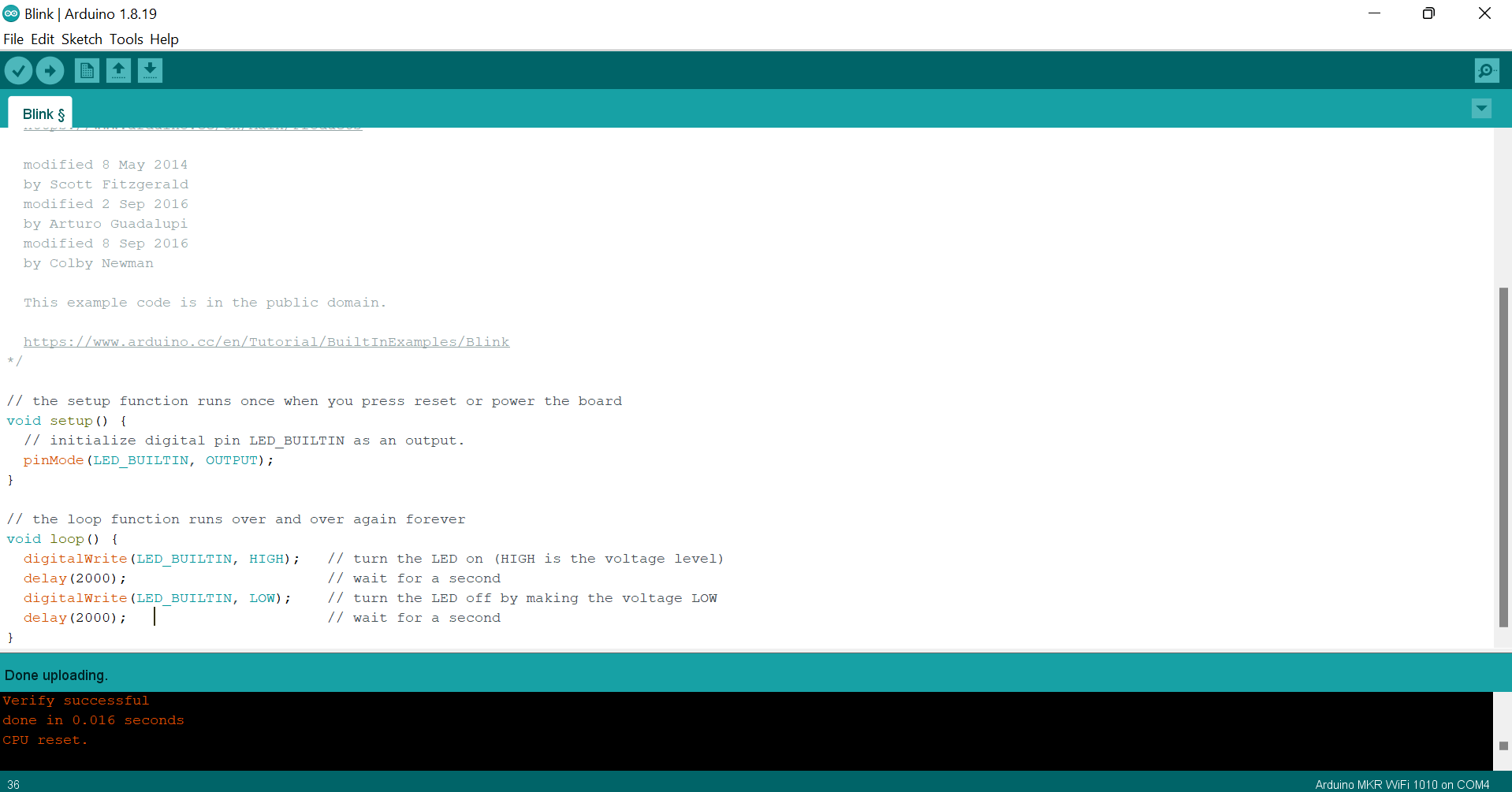
Blink after 2 seconds
// the setup function runs once when you press reset or power the board
void setup() {
  // initialize digital pin LED_BUILTIN as an output.
  pinMode(LED_BUILTIN, OUTPUT);
}

// the loop function runs over and over again forever
void loop() {
  digitalWrite(LED_BUILTIN, HIGH);   // turn the LED on (HIGH is the voltage level)
  delay(2000);                       // wait for two seconds
  digitalWrite(LED_BUILTIN, LOW);    // turn the LED off by making the voltage LOW
  delay(2000);                       // wait for two seconds
}
Tasks
Random Blink
I modified the blink example code by adding the random() function to generate a random number between 300 and 3000 and put it as an input in the delay() function.
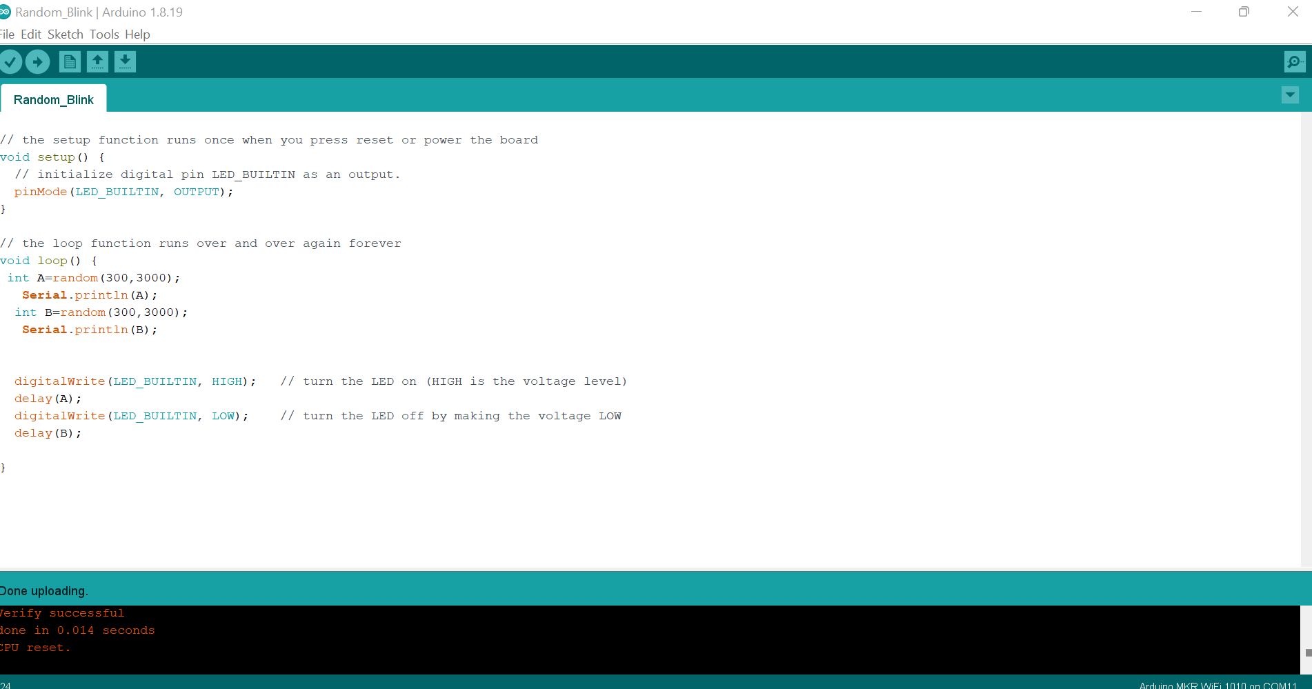
// the setup function runs once when you press reset or power the board
void setup() {
  // initialize digital pin LED_BUILTIN as an output.
  pinMode(LED_BUILTIN, OUTPUT);
}

// the loop function runs over and over again forever
void loop() {
 int A=random(300,3000);
   Serial.println(A);
  int B=random(300,3000);
   Serial.println(B);


  digitalWrite(LED_BUILTIN, HIGH);   // turn the LED on (HIGH is the voltage level)
  delay(A);
  digitalWrite(LED_BUILTIN, LOW);    // turn the LED off by making the voltage LOW
  delay(B);

}
Original code file download link
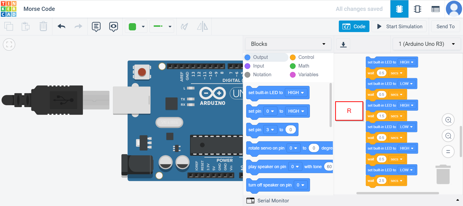
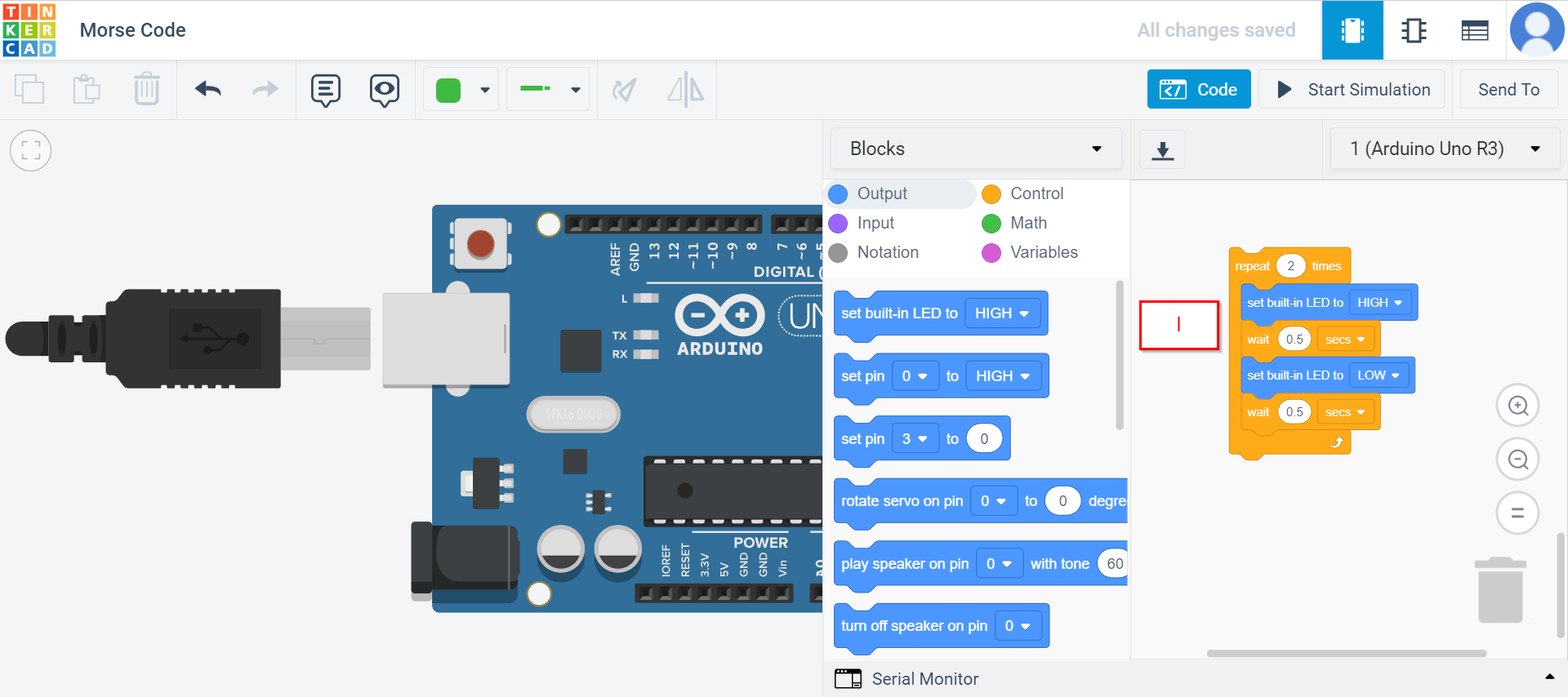
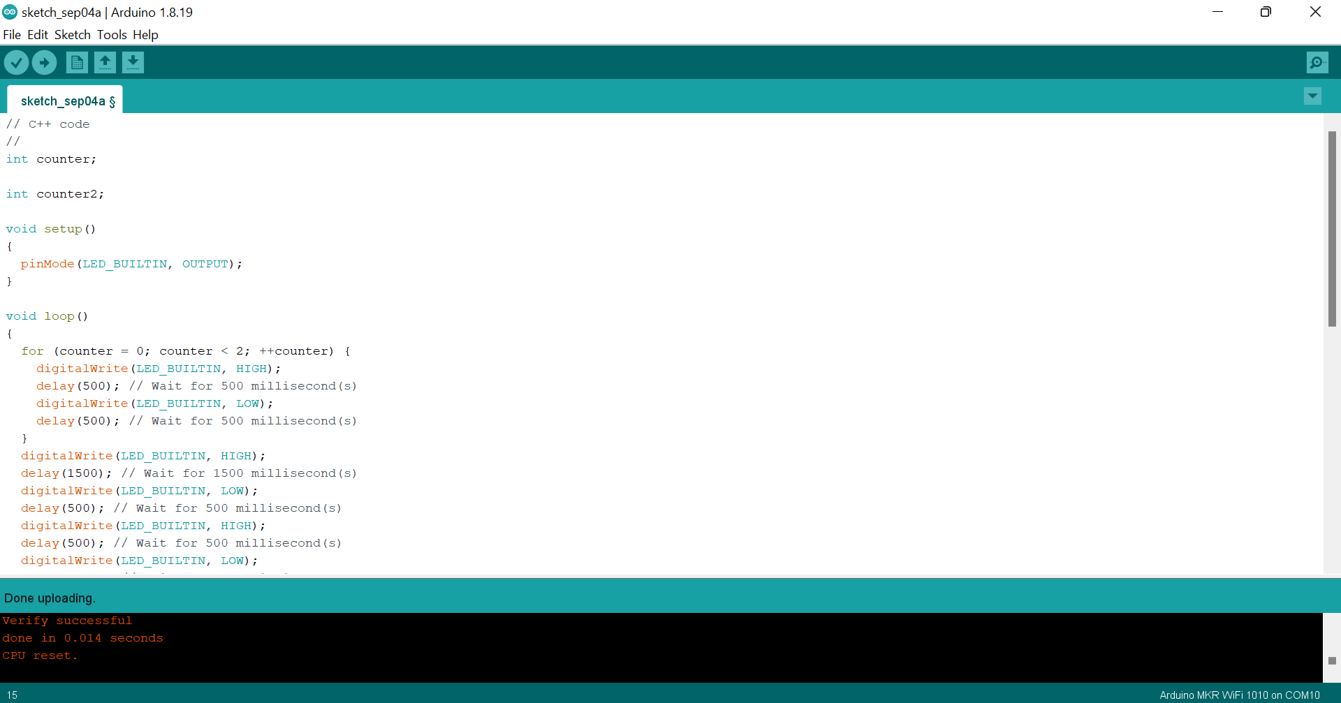
Blink in Morse code
Morse Code is a code for translating letters to dots • and dashes —. These represent a short and long signal duration.
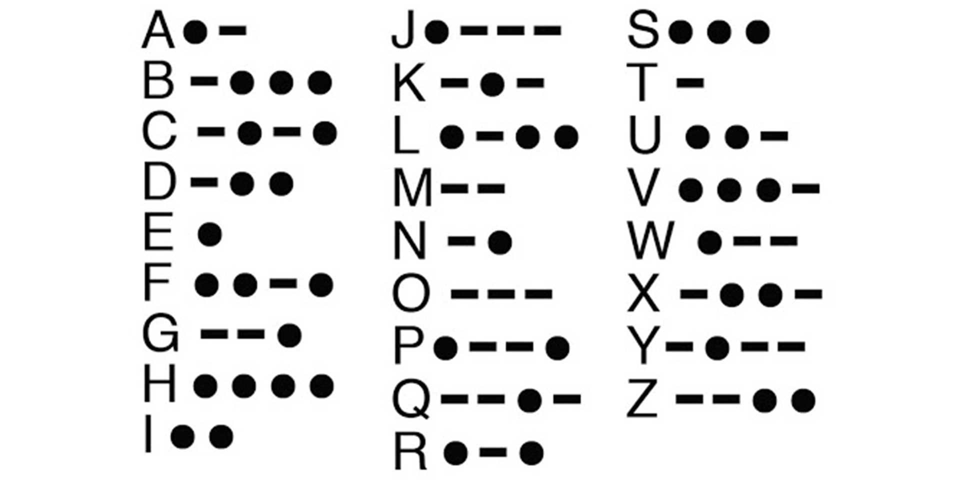
I translated my (nick/half) name in morsecode using Morse code translator.
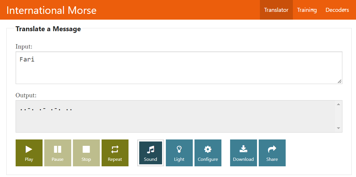
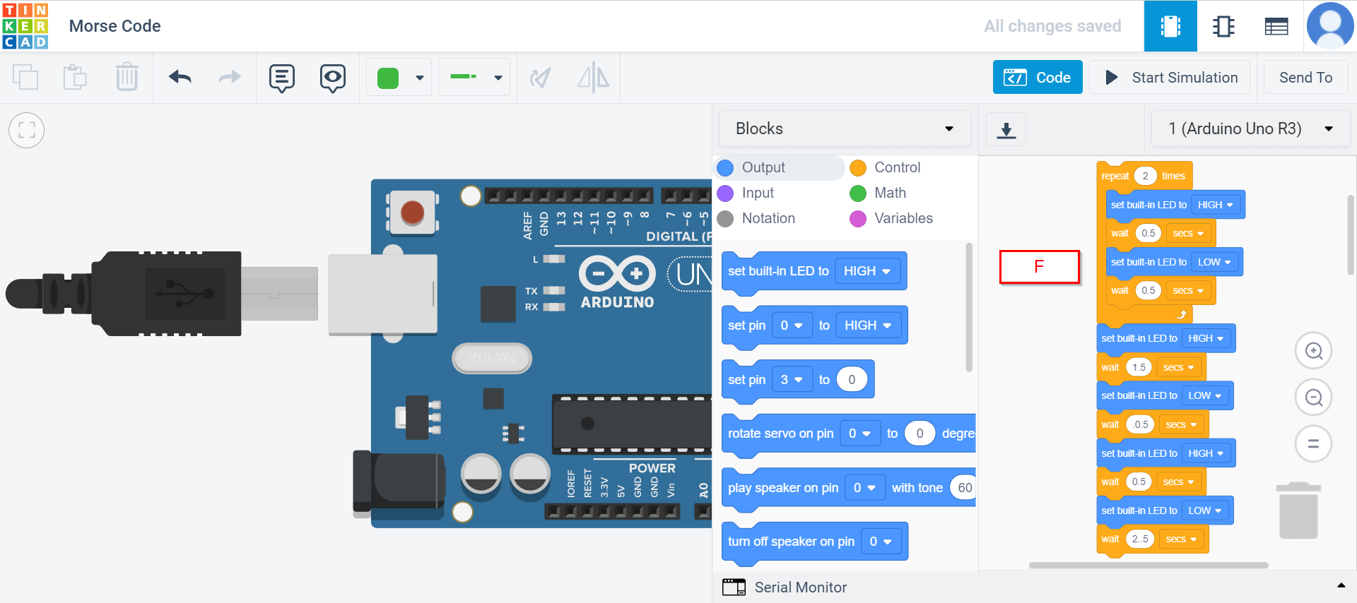
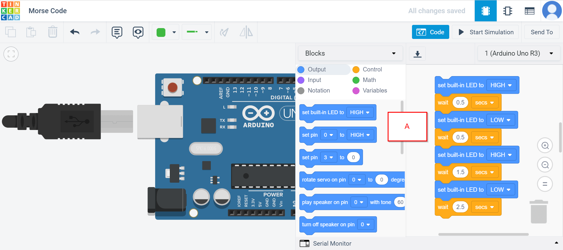
I used tinkercad for this task. In tinkercad, I went to circuits and started functional block programming by keeping these in mind:
- ”.” should be 0.5 seconds (On).
- ”-” should be 1.5 seconds (On).
- Space (off) between “2 dots” or “2 dashes” is (0.5) seconds.
- Space (off) between “one letter” and the “other” should be 2.5 seconds.
// C++ code
//
int counter;

int counter2;

void setup()
{
  pinMode(LED_BUILTIN, OUTPUT);
}

void loop()
{
  for (counter = 0; counter < 2; ++counter) {
    digitalWrite(LED_BUILTIN, HIGH);
    delay(500); // Wait for 500 millisecond(s)
    digitalWrite(LED_BUILTIN, LOW);
    delay(500); // Wait for 500 millisecond(s)
  }
  digitalWrite(LED_BUILTIN, HIGH);
  delay(1500); // Wait for 1500 millisecond(s)
  digitalWrite(LED_BUILTIN, LOW);
  delay(1000); // Wait for 1000 millisecond(s)
  digitalWrite(LED_BUILTIN, HIGH);
  delay(500); // Wait for 500 millisecond(s)
  digitalWrite(LED_BUILTIN, LOW);
  delay(2000); // Wait for 2000 millisecond(s)

  digitalWrite(LED_BUILTIN, HIGH);
  delay(500); // Wait for 500 millisecond(s)
  digitalWrite(LED_BUILTIN, LOW);
  delay(500); // Wait for 500 millisecond(s)
  digitalWrite(LED_BUILTIN, HIGH);
  delay(1500); // Wait for 1500 millisecond(s)
  digitalWrite(LED_BUILTIN, LOW);
  delay(2500); // Wait for 2500 millisecond(s)

  digitalWrite(LED_BUILTIN, HIGH);
  delay(500); // Wait for 500 millisecond(s)
  digitalWrite(LED_BUILTIN, LOW);
  delay(500); // Wait for 500 millisecond(s)
  digitalWrite(LED_BUILTIN, HIGH);
  delay(1500); // Wait for 1500 millisecond(s)
  digitalWrite(LED_BUILTIN, LOW);
  delay(500); // Wait for 500 millisecond(s)
  digitalWrite(LED_BUILTIN, HIGH);
  delay(500); // Wait for 500 millisecond(s)
  digitalWrite(LED_BUILTIN, LOW);
  delay(2500); // Wait for 2500 millisecond(s)

  for (counter2 = 0; counter2 < 2; ++counter2) {
    digitalWrite(LED_BUILTIN, HIGH);
    delay(500); // Wait for 500 millisecond(s)
    digitalWrite(LED_BUILTIN, LOW);
    delay(500); // Wait for 500 millisecond(s)
  }
}
Original code file download link
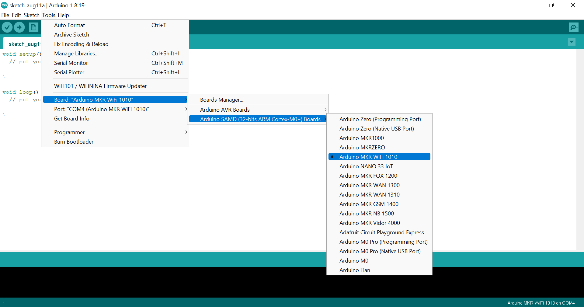
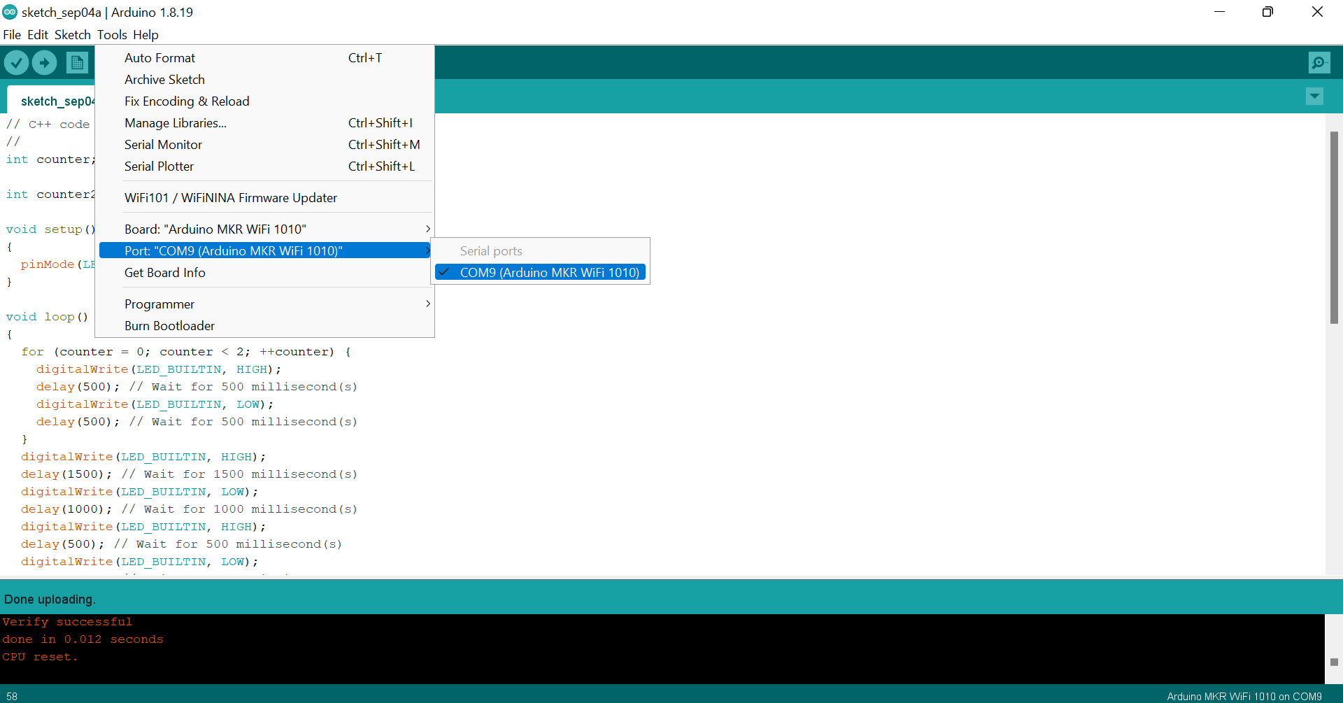
Problem Encountered
I kept getting this message “could not find a board on a selected port”. I thought there is something wrong with USB cables.
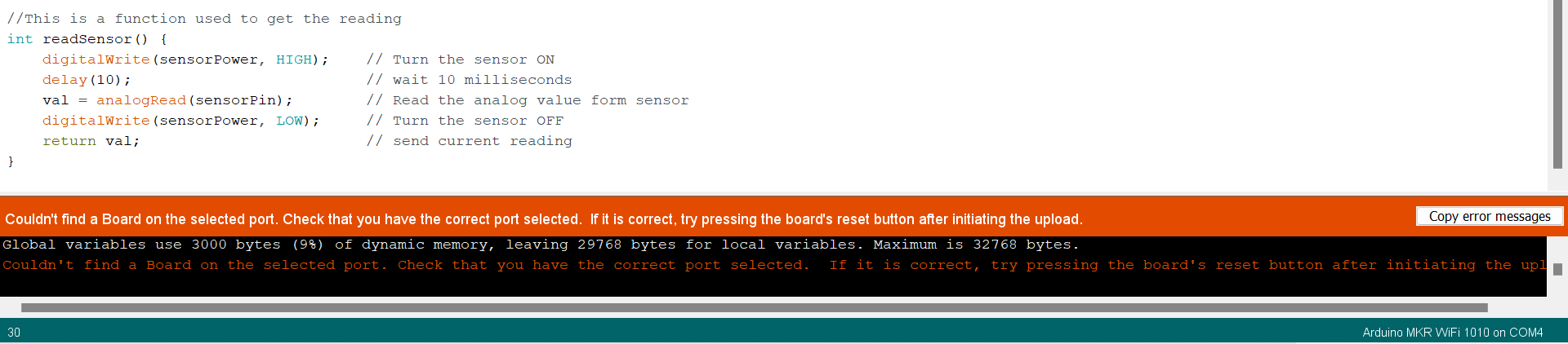
But, I found out that in addition to selecting the right board, I also needed to select the right port.
Useful links
- What is a Microcontroller and How Does it Work?
- Arduino MKR WiFi 1010
- Arduino IDE
- What is morse code?
- Morse code translator