6. Input & Output device
This week I learnt about input and output devices. Also, I learnt how to add a sensor to a microcontroller board and read it, and how to add an output device to a microcontroller board and program it to do something.
Input and Output device
Here’s a brief introduction to input and output devices.
An input device is something you connect to a computer that sends information into the computer. An input device can send data to another device, but it cannot receive data from another device. Examples of output devices include the keyboard, mouse and microphone.
An output device is something you connect to a computer that has information sent to it. An output device can receive data from another device and generate output with that data, but it cannot send data to another device. Examples of input devices include monitor and speaker.
Most devices are only input devices or output devices, as they can only accept data input from a user or output data generated by a computer. However, some devices can accept input and display output, and they are referred to as I/O devices (input/output devices).
In computing, I/O (input/output) is the communication between an information processing system, such as a computer, and the outside world, possibly a human or another information processing system. Inputs are the signals or data received by the system and outputs are the signals or data sent from it. The term can also be used as part of an action; to “perform I/O” is to perform an input or output operation. I/O devices are the items of hardware used by a human (or other system) to communicate with a computer. For instance, a keyboard or computer mouse is an input device for a computer, while monitors and printers are output devices. Devices for communication between computers, such as modems and network cards, typically perform both input and output operations.
Working with Input device
Task 1
- Measure something: Add a sensor to a microcontroller board and read it.
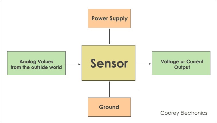
Sensors are devices that detect changes in physical, electrical, or other quantities. So, it produces an electrical or optical signal output as an acknowledgement of the change in that specific quantity. So, a sensor is a module or chip that observes the changes happening in the physical world and sends feedback to the microcontroller or microprocessor. Excitation (power supply) and grounding must be provided to the sensor for it to work properly.
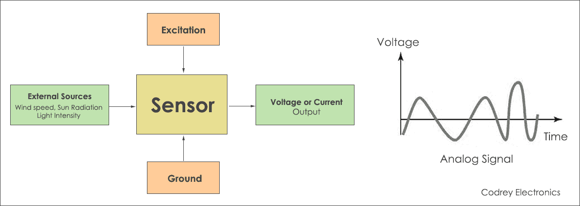
All types of sensors can be basicall classified into analog and digital sensors.
Analog Sensors measure the external parameters and give an analog voltage as an output. They produce a continuous output signal or voltage which is proportional to the quantity being measured. The output voltage may be from the range of 0 to 5V.
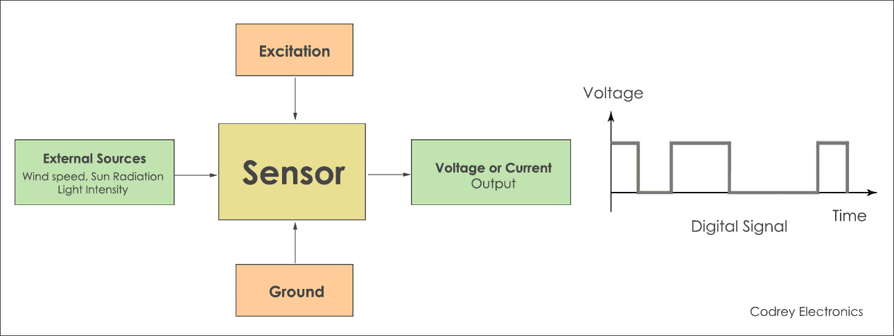
Digital Sensors act as electronic sensors where data is digitally converted and transmitted. Digital sensors produce discrete values (0s and 1s) or ‘binary’ signals.
Water Level Sensor
Water level sensor can be used to measure the water level, monitor a sump pit, detect rainfall or detect leakage. If you have ever had a water heater explode or ever tried to make submersible electronics, then you know how important it is to detect when water is around. With this Water Level Sensor, you can do just that!
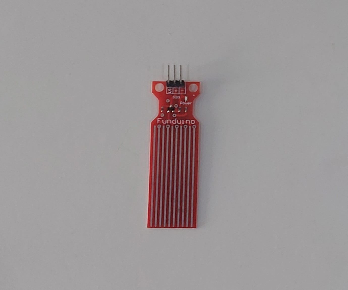
The water level sensor is super easy to use and only has 3 pins to connect.
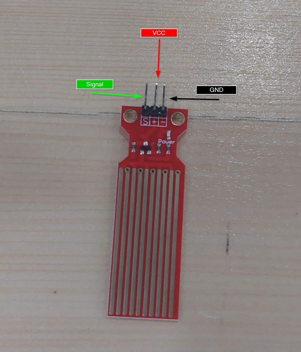
S (Signal) pin is an analog output that will be connected to one of the analog inputs on your Arduino.
+(VCC) pin supplies power for the sensor. It is recommended to power the sensor with between 3.3V – 5V. Please note that the analog output will vary depending on what voltage is provided for the sensor.
–(GND) is a ground connection.
Water Level Sensing Basic Example
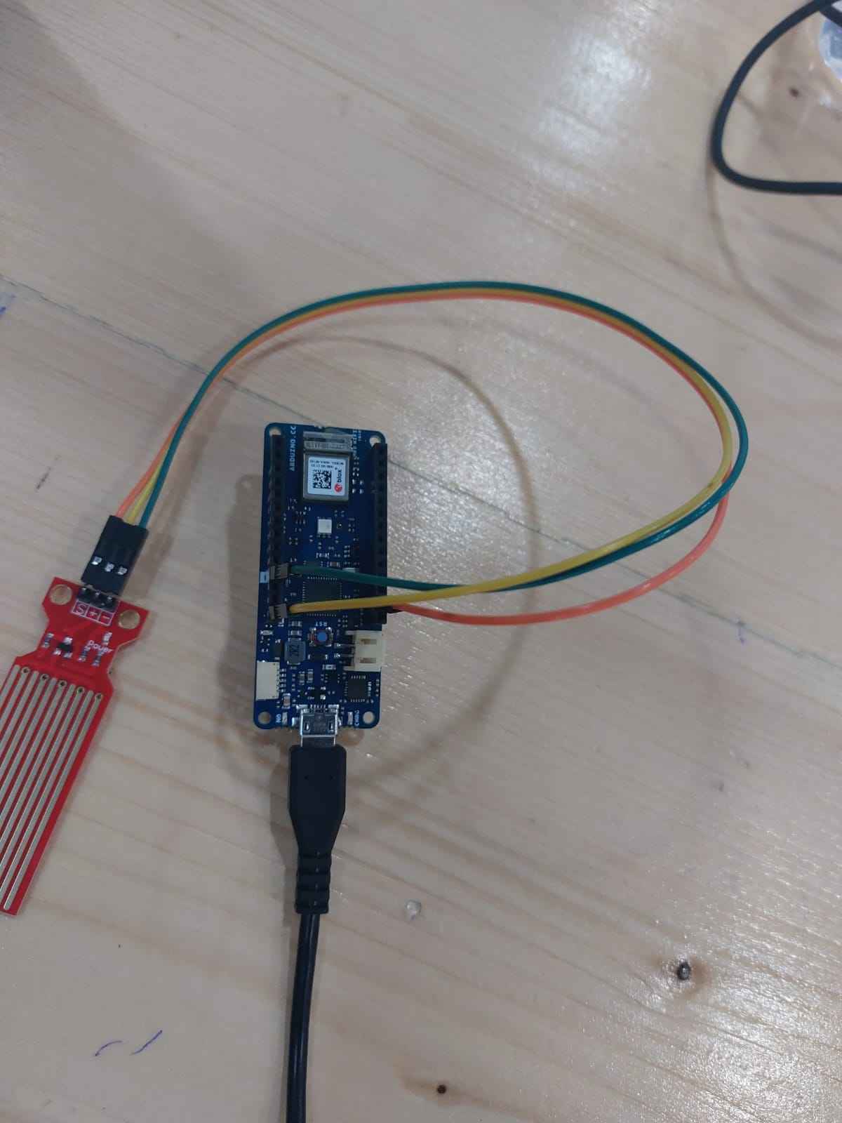
First of all, I wired a Water Level Sensor with Arduino.
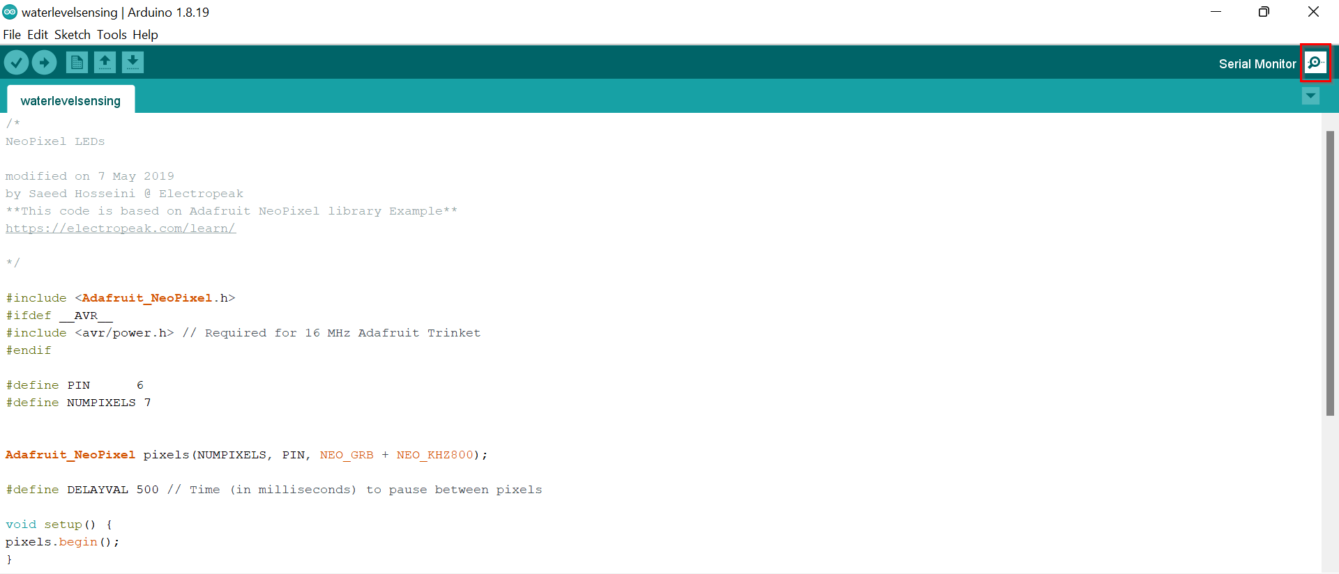
Once the circuit was built, I uploaded the following sketch to Arduino.
// Sensor pins
#define sensorPower 7
#define sensorPin A0

// Value for storing water level
int val = 0;

void setup() {
    // Set D7 as an OUTPUT
    pinMode(sensorPower, OUTPUT);

    // Set to LOW so no power flows through the sensor
    digitalWrite(sensorPower, LOW);

    Serial.begin(9600);
}

void loop() {
    //get the reading from the function below and print it
    int level = readSensor();

    Serial.print("Water level: ");
    Serial.println(level);

    delay(1000);
}

//This is a function used to get the reading
int readSensor() {
    digitalWrite(sensorPower, HIGH);    // Turn the sensor ON
    delay(10);                          // wait 10 milliseconds
    val = analogRead(sensorPin);        // Read the analog value form sensor
    digitalWrite(sensorPower, LOW);     // Turn the sensor OFF
    return val;                         // send current reading
}
Original code file download link
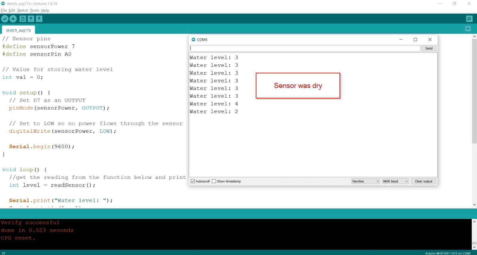
Once the sketch was uploaded, I opened a Serial Monitor window to see the output from the Arduino.
I saw a following values when sensor was dry:
To see it sense water, I took a glass of water and slowly put the sensor in it.
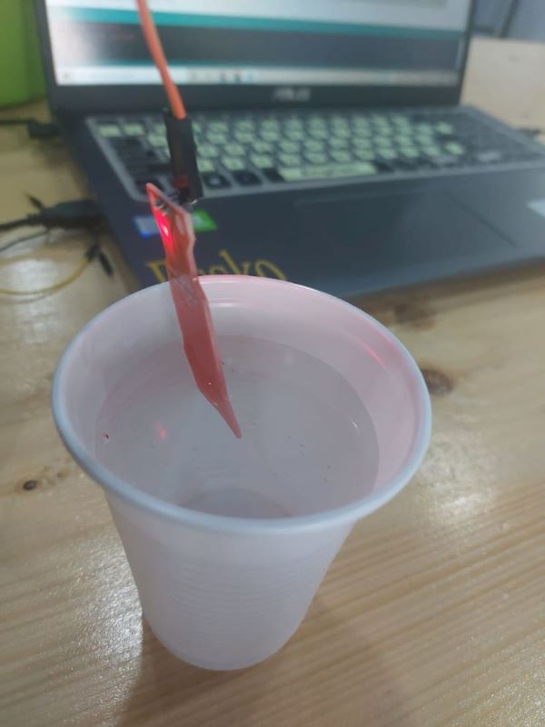
I saw a following values when sensor was submerged partially:
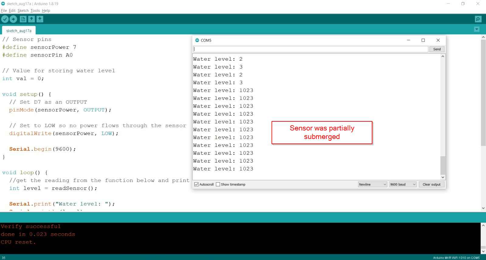
- The sensor is not designed to be fully submersed, be careful to install it so that only the exposed traces on the PCB will come in contact with water.
Explaination
The sketch begins with the declaration of the Arduino pins to which the sensor’s + VCC and signal pins are connected.
#define sensorPower 7
#define sensorPin A0
Next, a variable val is defined that stores the current water level.
int val = 0;
Now in the Setup section, we first declare the power connection to the sensor as output, then we set it low so no power flows through the sensor initially. We also setup the serial monitor.
pinMode(sensorPower, OUTPUT);
digitalWrite(sensorPower, LOW);
Serial.begin(9600);
In the loop section, we call readSensor() function repeatedly at the interval of one second and print the returned value.
Serial.print("Water level: ");
Serial.println(readSensor());
delay(1000);
The readSensor() function is used to get the current water level. It turns the sensor ON, waits for 10 milliseconds, reads the analog value form sensor, turns the sensor OFF and then returns the analog value.
int readSensor() {
    digitalWrite(sensorPower, HIGH);
    delay(10);
    val = analogRead(sensorPin);
    digitalWrite(sensorPower, LOW);
    return val;
}
Remarks
Working with the water level sensor was fun. I got to know about the specifications of a water level sensor and how and where we can use it. The code which I got from the tutorial was simple and had comments written about every line, so it was easy to understand. By interfacing a water level sensor to a microcontroller, I also learnt how we can read input device values on a serial monitor.
Working with Output devices
Task 2
- Add an output device to a microcontroller board and program it to do something.
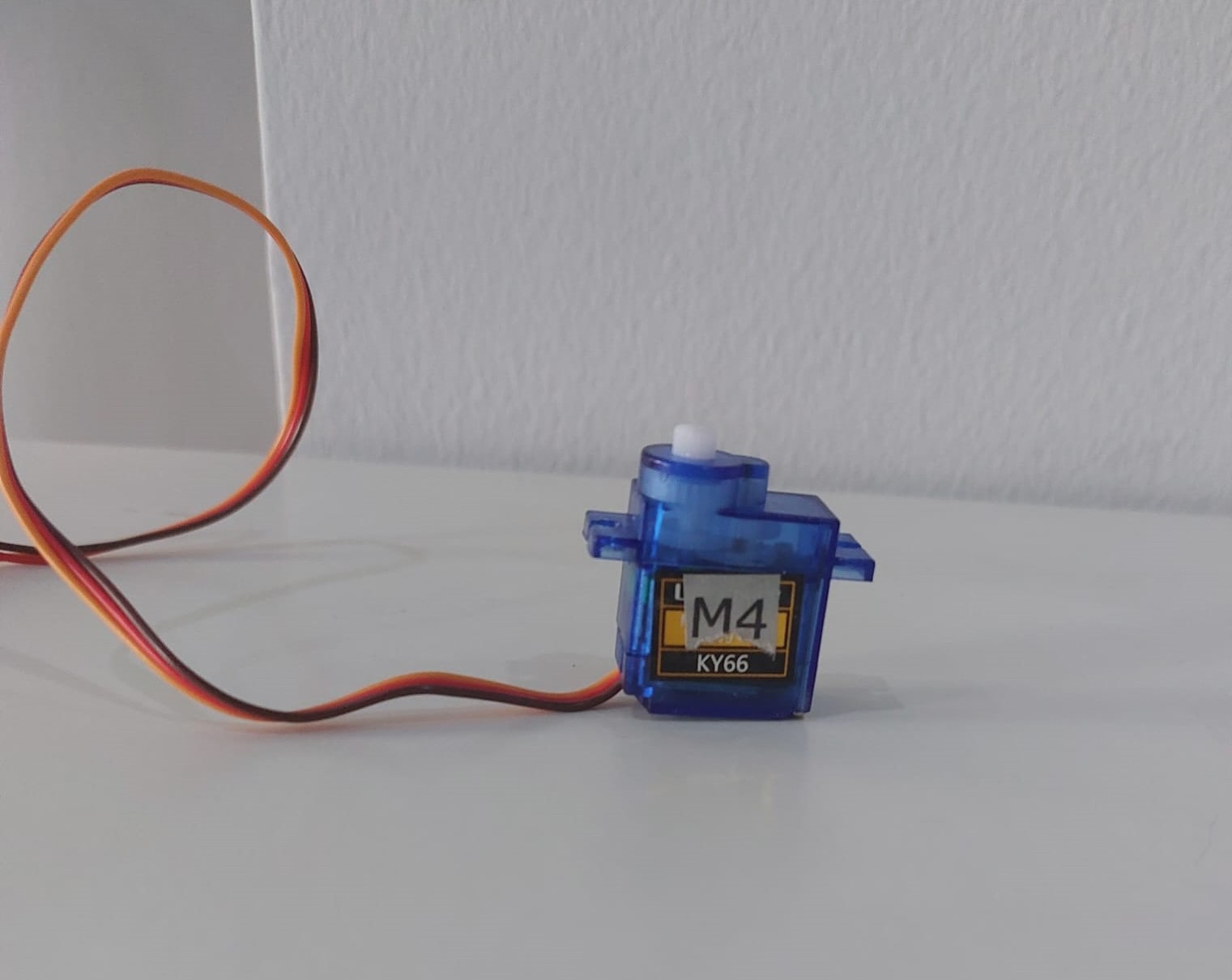
Servo Motor
A servo motor is a rotary actuator that allows for precise control of angular position. It consists of a motor coupled to a sensor for position feedback. It also requires a servo drive to complete the system. The drive uses the feedback sensor to precisely control the rotary position of the motor.
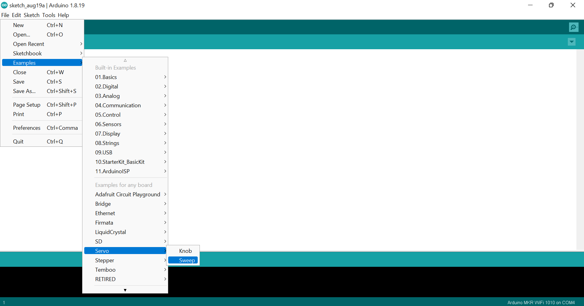
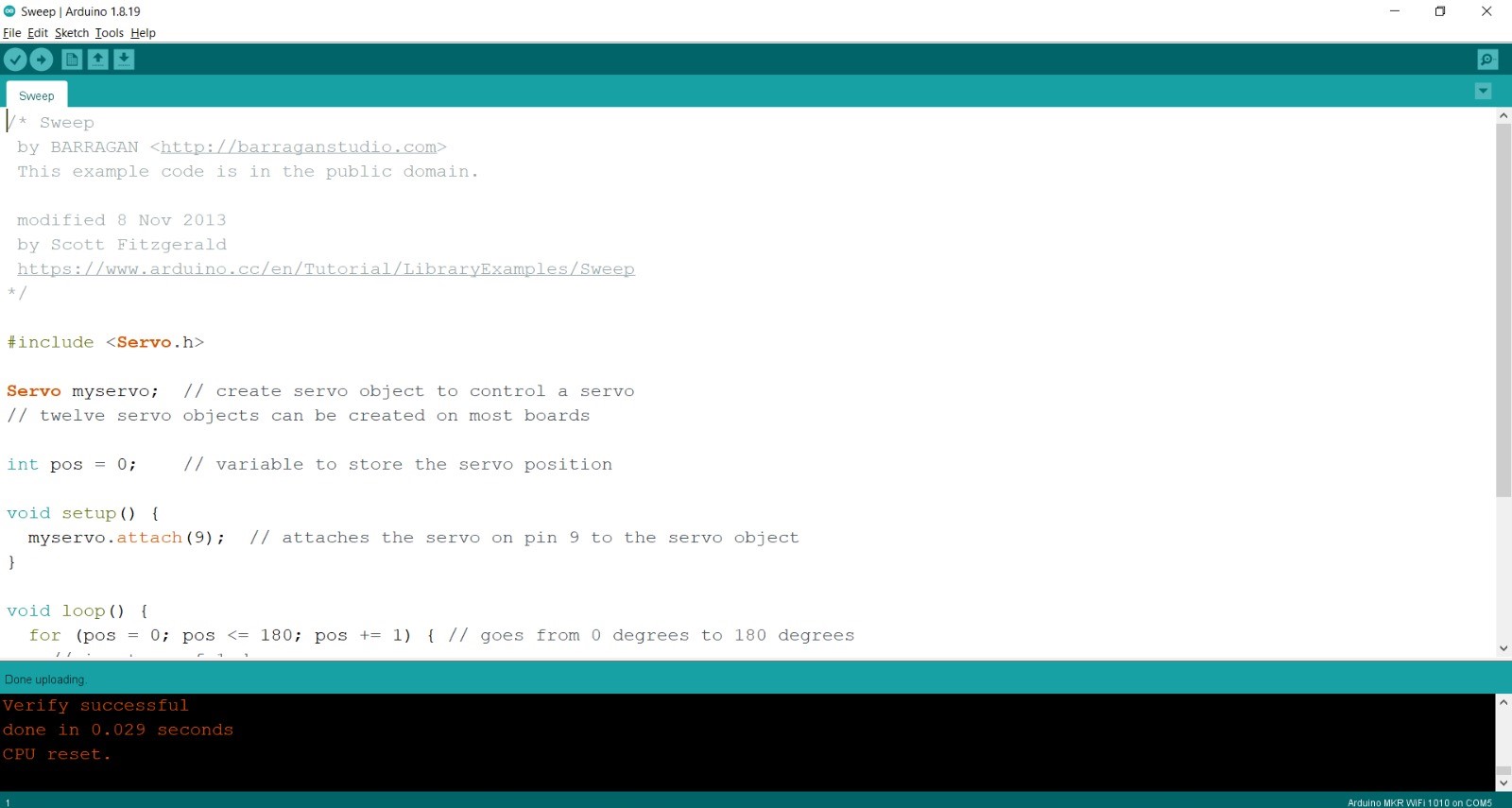
Sweep Example
It will Sweep the shaft of a RC servo motor back and forth across 180 degrees.
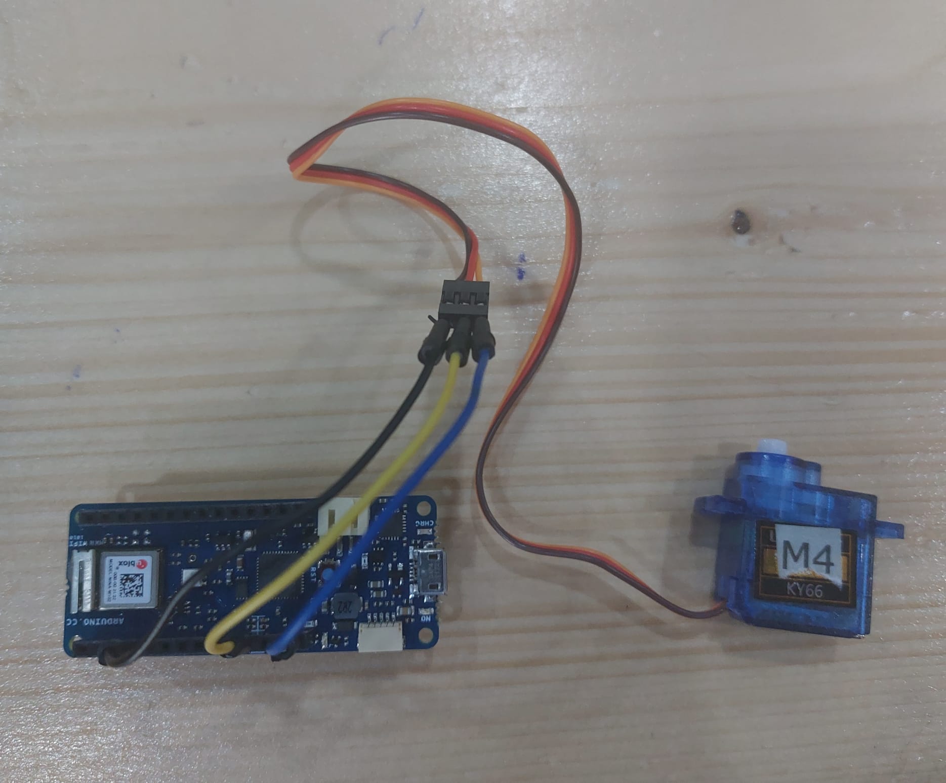
For this, connect the servo motor to +5V, GND and pin 9. Servo motors have three wires: power, ground, and signal. The power wire is typically red, and should be connected to the 5V pin on the Arduino board. The ground wire is typically black or brown and should be connected to a ground pin on the board. The signal pin is typically yellow or orange and should be connected to PWM pin on the board. In this example, it is pin number 9.
#include <Servo.h>

Servo myservo;

int pos = 0;

void setup()
{
  myservo.attach(9);
}

void loop() {
  for (pos = 0; pos <= 180; pos += 1)
  {
    myservo.write(pos);
    delay(15);
  }
  for (pos = 180; pos >= 0; pos -= 1)
  {
    myservo.write(pos);
    delay(15);
  }
}
Explaination
First of all, in this sweep example, the servo library was included. Servo library allows Arduino boards to control a variety of servo motors. This library can control a great number of servos. It makes careful use of timers. The library can control 12 servos using only 1 timer.
#include <Servo.h>
Creating a servo object to control a servo.
Servo myservo;
Declaring a variable to store the servo position.
int pos = 0;
Attaching the servo on pin 9 to the servo object.
myservo.attach(9); // attaches the servo on pin 9 to the servo object
Servo will go from 0 degrees to 180 degrees, in steps of 1 degree.
for (pos = 0; pos <= 180; pos += 1)
Telling servo to go to position in variable ‘pos’.
myservo.write(pos);
Waits 15ms for the servo to reach the position.
delay(15);
Servo will go from 180 degrees to 0 degrees.
for (pos = 180; pos >= 0; pos -= 1)
Task 3 (Group Work)
- Make an KY-009 RGB Full Color LED SMD Module fade through colors.
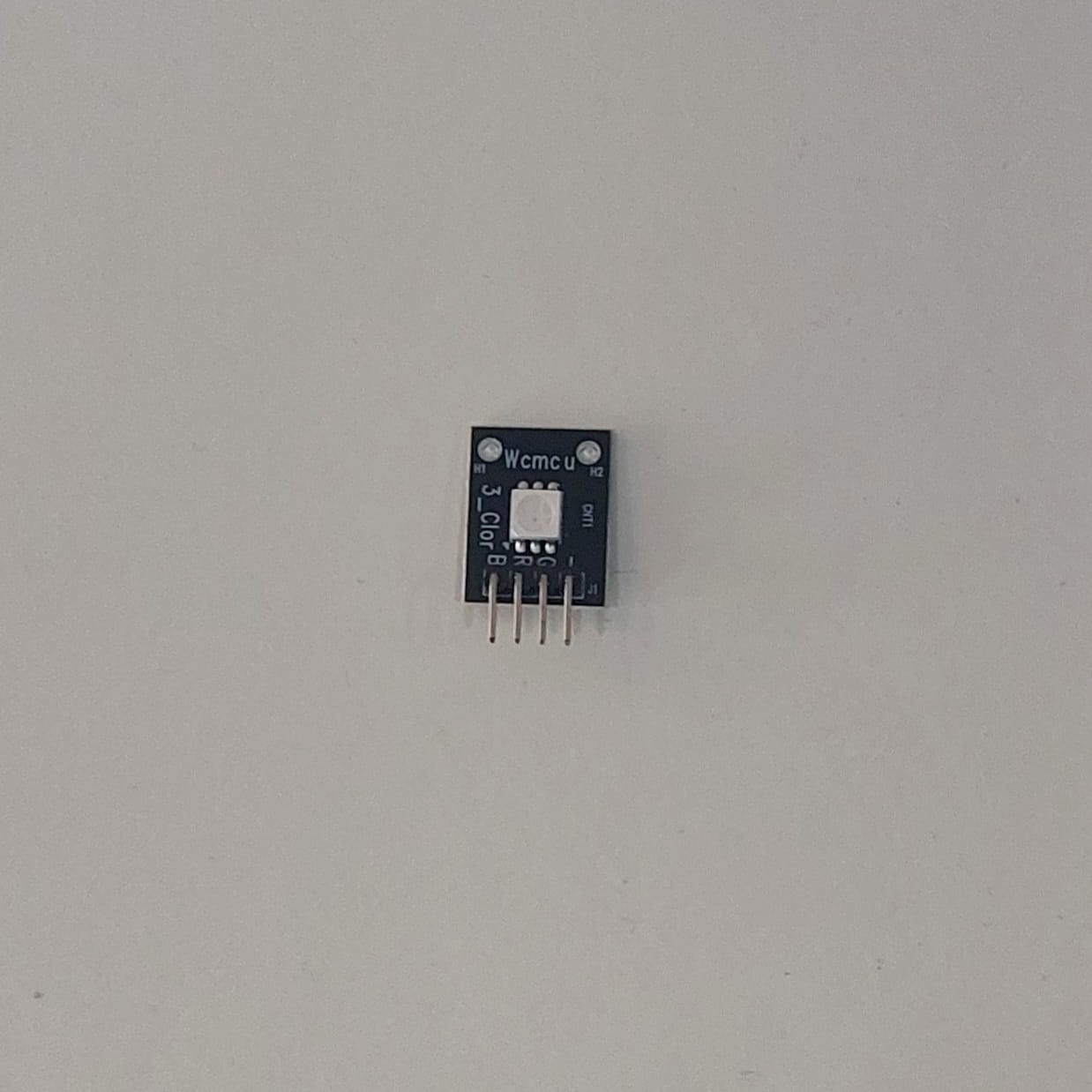
KY-009 RGB Full Color LED SMD Module
The KY-009 RGB Full Color LED module emits a range of colors by mixing red, green, and blue light. Each color is adjusted by using PWM. Compatible with popular electronics platforms like Arduino, Raspberry Pi and ESP32. Control of the module with the Arduino can be achieved Cool lighting effects.
Fade Example
void lightRGB(int r, int g, int b){
  analogWrite(RED, r);
  analogWrite(GREEN, g);
  analogWrite(BLUE, b);
}

// Pins
#define BLUE 3
#define GREEN 5
#define RED 6
#define delayTime 10 // fading time
int MAX_LUM = 255;
int redVal,greenVal,blueVal;
void setup()
{
  pinMode(RED, OUTPUT);
  pinMode(GREEN, OUTPUT);
  pinMode(BLUE, OUTPUT);
  digitalWrite(RED, HIGH);
  digitalWrite(GREEN, LOW);
  digitalWrite(BLUE, LOW);
}
void loop()
{
  redVal = MAX_LUM; // choose a Val between 1 and 255 to change the color.
  greenVal = 0;
  blueVal = 0;
  for(int i = 0; i < MAX_LUM; i += 1) // fades out red bring green full when i=255
  {
    redVal -= 1;
    greenVal += 1;
    lightRGB(redVal, greenVal, blueVal);
    delay(delayTime);
  }
  redVal = 0;
  greenVal = MAX_LUM;
  blueVal = 0;
  for(int i = 0; i < MAX_LUM; i += 1) // fades out green bring blue full when i=255
  {
    greenVal -= 1;
    blueVal += 1;
    lightRGB(redVal, greenVal, blueVal);
    delay(delayTime);
  }
  redVal = 0;
  greenVal = 0;
  blueVal = MAX_LUM;
  for(int i = 0; i < MAX_LUM; i += 1) // fades out blue bring red full when i=255
  {
    // The following code has been rearranged to match the other two similar sections
    blueVal -= 1;
    redVal += 1;
    lightRGB(redVal, greenVal, blueVal);
    delay(delayTime);
  }
}
void lightRGB(int r, int g, int b){
  analogWrite(RED, r);
  analogWrite(GREEN, g);
  analogWrite(BLUE, b);
}
Original code file download link
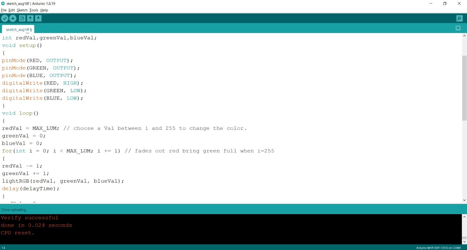
Explaination
In this example, we move from one color to another gradually. For this, we vary the values R, G, B which we send to the corresponding pins. In this case, it is more practical and readable to use a function that assigns the PWM value to the correct output for each color. To do so we create the function lightRGB that takes 3 integers as inputs, which are the pwm command, and write this value to the RGB pins. Once the function created, it can be used in the main code (in loop function) and control three outputs with one line of code.
Problem Encountered
We had tried so many different codes, but every time we were only getting the red color.
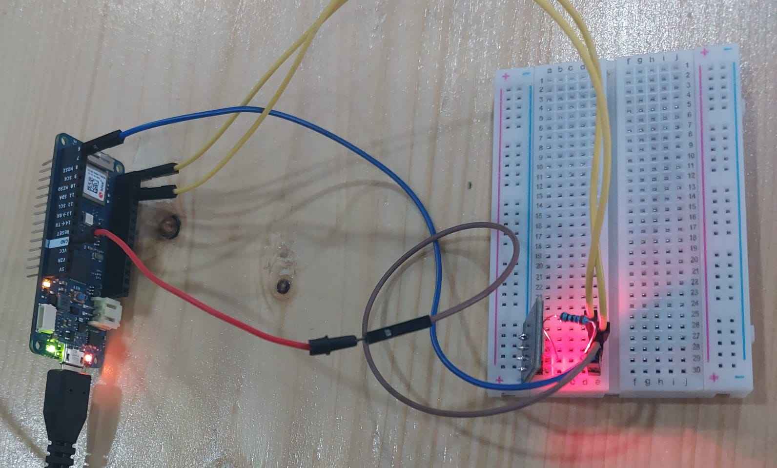
Because the sensor we were using was a common anode sensor, while we were following the connections for the common cathode sensor as it was labeled. We fixed this problem by putting the ground pin into the VCC pin instead. Finally, we uploaded the code that we got from here and changed the pins in the code also, and it started working properly.
Remarks
From these tasks, I learnt how to control servo motors and KY-009 RGB Led. I also learnt from interfacing output devices to the microcontroller that we can also need resistors and how to use them. As I mentioned above, we faced a problem where we were only getting a red light in the KY-009 RGB Led. We thought there were some problems with codes, so we tried different codes and tried to change them also. Because of this, we become familiar with many codes and how they work.
Useful links
- What are input and output devices?
- What are sensors and how they work?
- What are the classification of sensors?
- How Water Level Sensor Works and Interface it with Arduino tutorial
- What is servo motor?
- Sweep example
- Servo library
- What is KY-009 RGB Full Color LED module?
- Modulate the color with the RGB LED