4. Embedded programming
This week I worked on Enbedded programing on an Arduino microcontroller that is to be coded and given commands using Arduino program.
Microcontroller
A microcontroller is a small and low-cost microcomputer, which is designed to perform the specific tasks of embedded systems like displaying microwave’s information, receiving remote signals, etc.
The general microcontroller consists of the processor, the memory (RAM, ROM, EPROM), Serial ports, peripherals (timers, counters), etc. However we will use a microcontroller called Arduino MKR WiFi 1010.
What is Arduino?
Arduino is an open-source electronics platform based on easy-to-use hardware and software. It’s intended for anyone making interactive projects. It is widely used in various fields like robotics.
The Arduino MKR Wifi 1010
MKR 1010 simplifies the prototyping of WiFi-based IoT applications, easily connected and configured to other Arduino products.
MKR 1010 has a total of 28 pins:
- 8 digital I/O pins
- 7 analog input pins
- 1 analog output pins
- 13 PMW pins
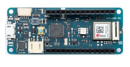
This is how MKR Wifi 1010 looks like:
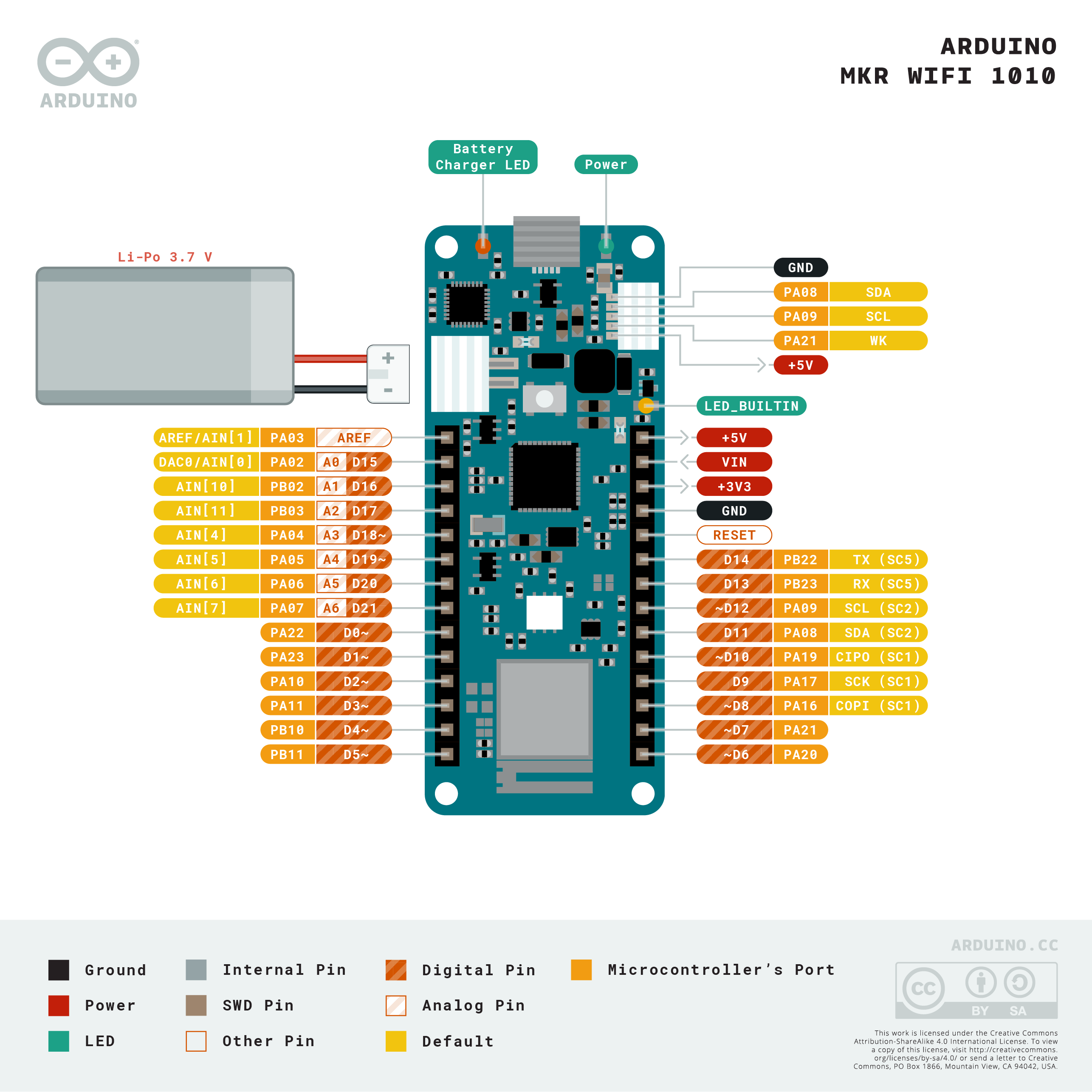
The pinout of the board is illustrated below:
Microcontroler datasheet
By visiting the following link, you can learn everything you need to know about the Microcontroler datasheet
After reading the datasheet of the Arduino MKR Wifi, I got to know about the specifications of the Arduino MKR Wifi. Where, I learned about its pins, which will be useful in completing our tasks. I got to know about the pins functions, which pin is analog and which pin is digital and which pins are PWM. Analog pins can be connected to analog sensors, and digital pins can be connected to digital inputs and outputs. PWM stands for Pulse Width Modulation and it is a technique used in controlling the brightness of LED, speed control of DC motor, controlling a servo motor or where you have to get analog output with digital means. The PWM pins are labeled with ~ sign on Arduino MKR Wifi. This information about pins will also be very useful for input and output assignment tasks.
Arduino program
We downloaded Arduino program, from this link
Easy mode
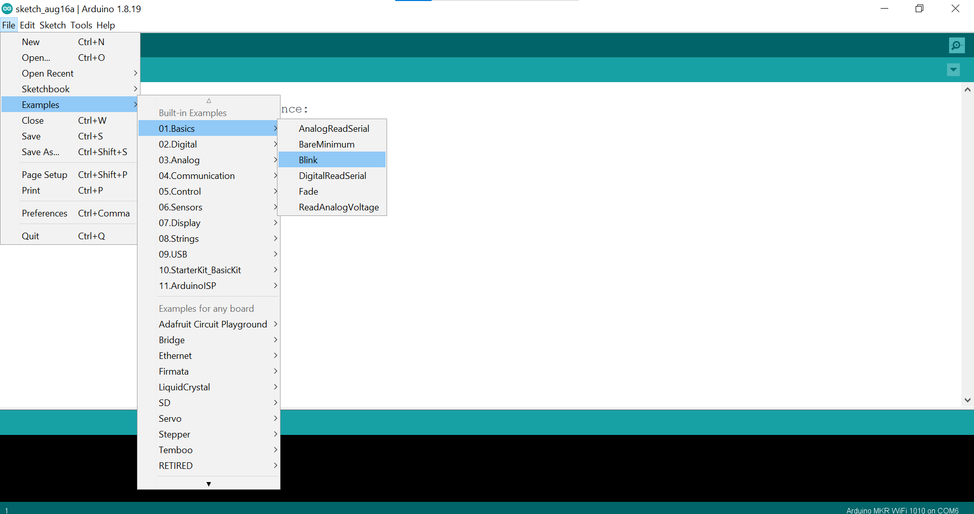
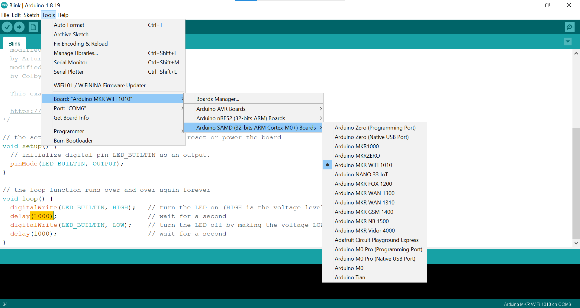
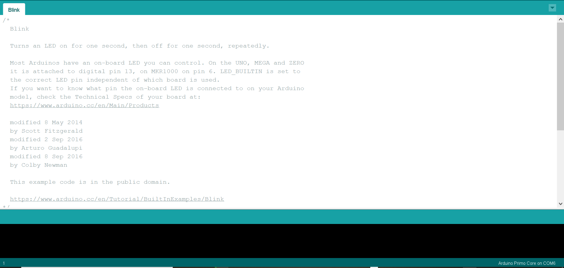
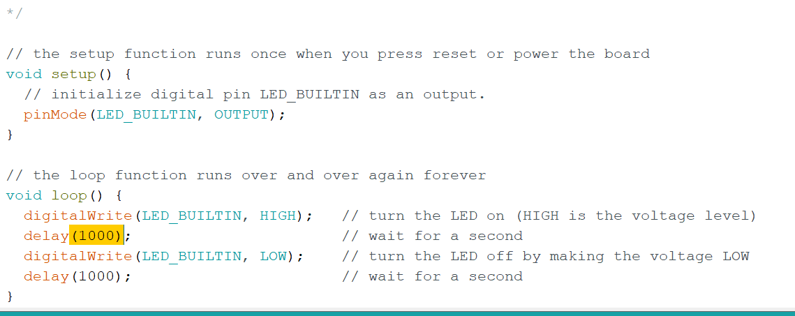
First, we did the blink example, following those steps:
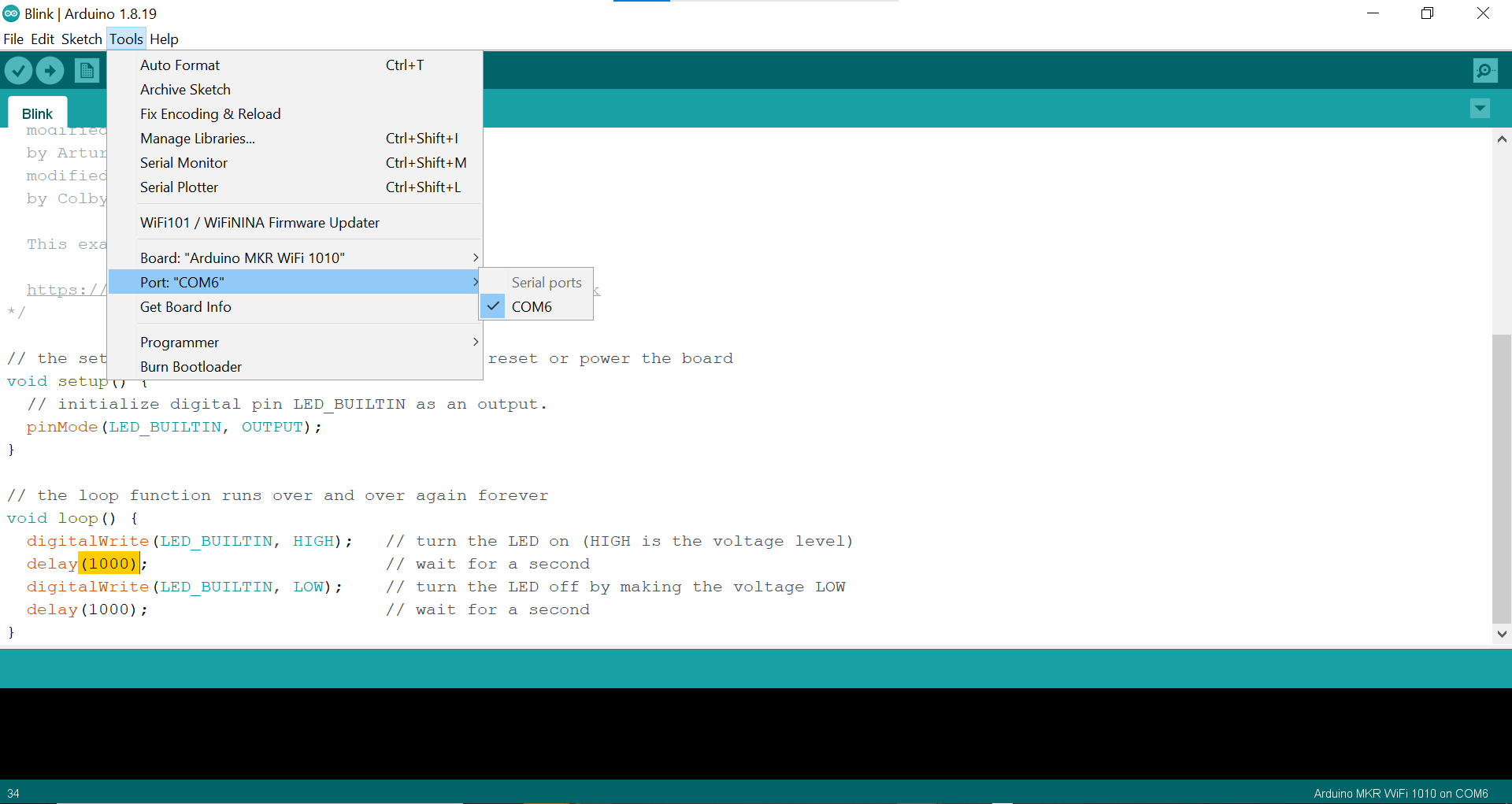
The delay time of the blink can be adjusted, 1000 is 1 second, 2000 is 2 second, etc
Random Blink
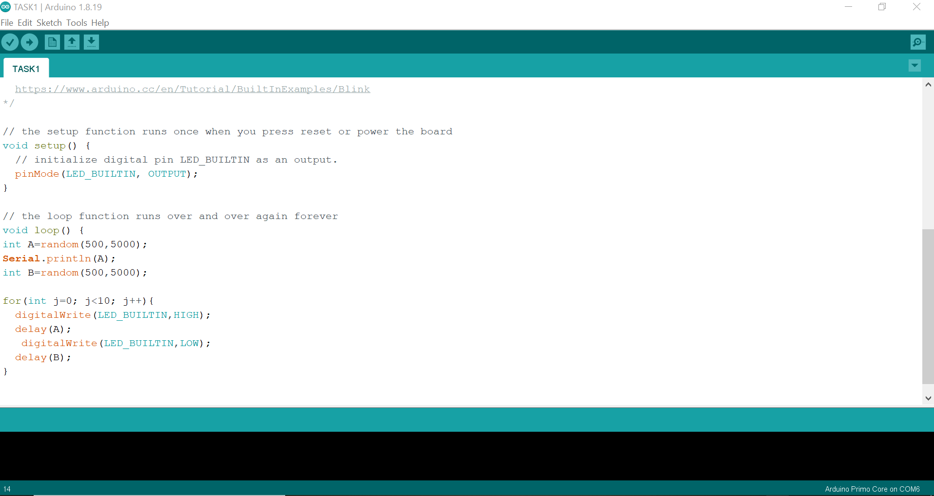
The code:
void setup() {
  // initialize digital pin LED_BUILTIN as an output.
  pinMode(LED_BUILTIN, OUTPUT);
}

// the loop function runs over and over again forever
void loop() {
int A=random(500,5000);
Serial.println(A);
int B=random(500,5000);

for(int j=0; j<10; j++){
  digitalWrite(LED_BUILTIN,HIGH);
  delay(A);
   digitalWrite(LED_BUILTIN,LOW);
  delay(B);
}
The results:
Medium Mode
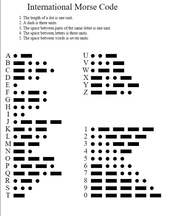
For the medium mode challenge, a morse code using arduino will be constructed to show my name“Hood”. First of all, a picture of the morse code that is to be used to make the word is provided below:
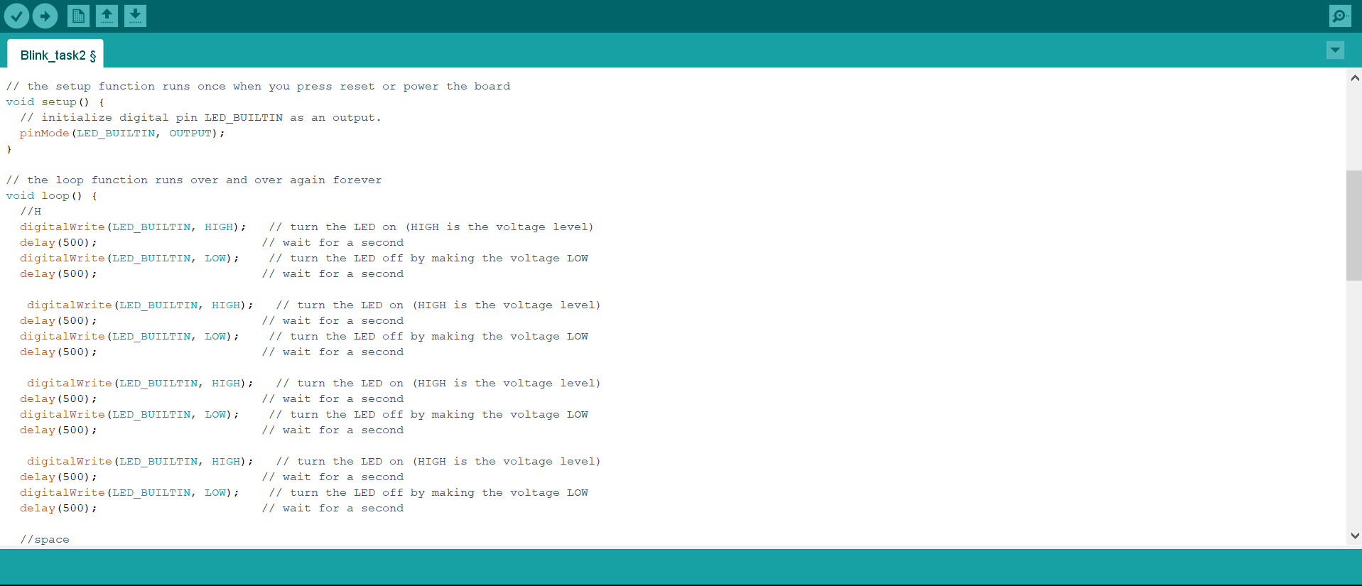
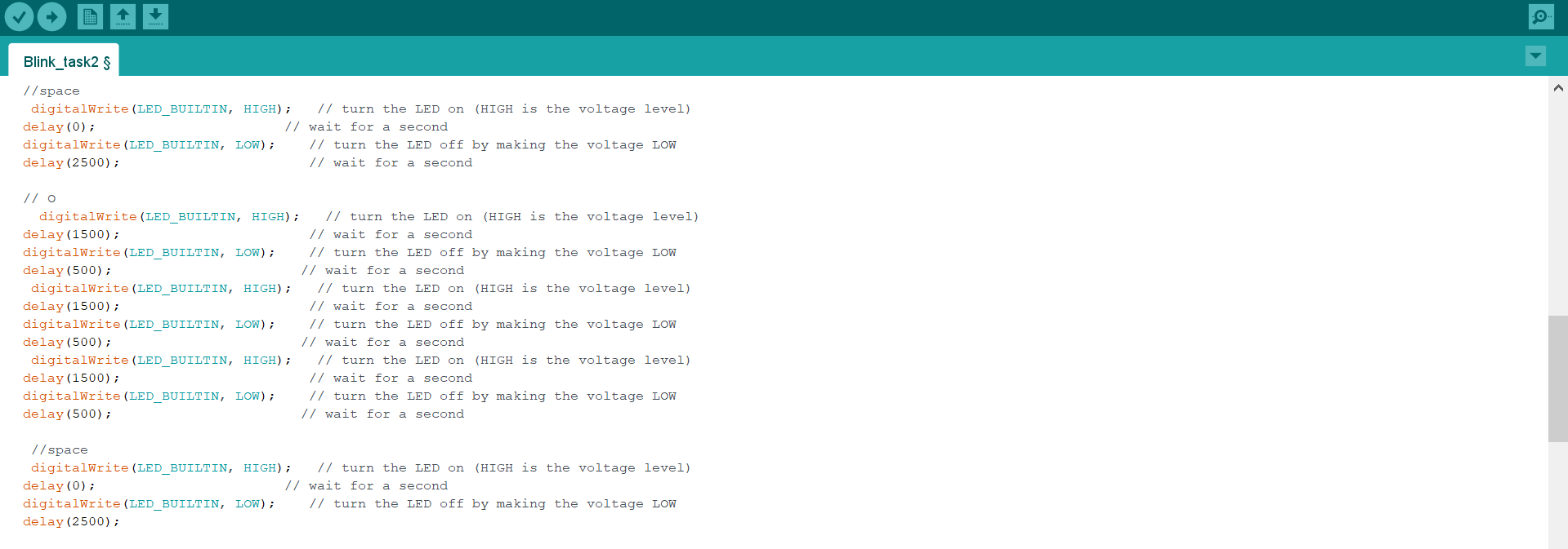
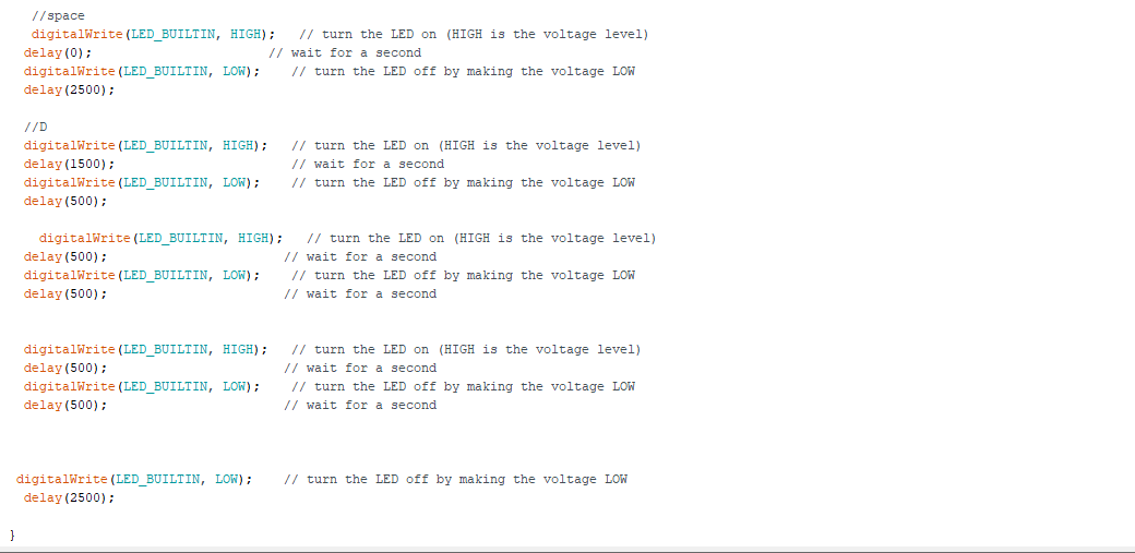
This is the code I used:
void setup() {
  // initialize digital pin LED_BUILTIN as an output.
  pinMode(LED_BUILTIN, OUTPUT);
}

// the loop function runs over and over again forever
void loop() {
  //H
  digitalWrite(LED_BUILTIN, HIGH);   // turn the LED on (HIGH is the voltage level)
  delay(500);                       // wait for a second
  digitalWrite(LED_BUILTIN, LOW);    // turn the LED off by making the voltage LOW
  delay(500);                       // wait for a second

   digitalWrite(LED_BUILTIN, HIGH);   // turn the LED on (HIGH is the voltage level)
  delay(500);                       // wait for a second
  digitalWrite(LED_BUILTIN, LOW);    // turn the LED off by making the voltage LOW
  delay(500);                       // wait for a second

   digitalWrite(LED_BUILTIN, HIGH);   // turn the LED on (HIGH is the voltage level)
  delay(500);                       // wait for a second
  digitalWrite(LED_BUILTIN, LOW);    // turn the LED off by making the voltage LOW
  delay(500);                       // wait for a second

   digitalWrite(LED_BUILTIN, HIGH);   // turn the LED on (HIGH is the voltage level)
  delay(500);                       // wait for a second
  digitalWrite(LED_BUILTIN, LOW);    // turn the LED off by making the voltage LOW
  delay(500);                       // wait for a second

  //space
   digitalWrite(LED_BUILTIN, HIGH);   // turn the LED on (HIGH is the voltage level)
  delay(0);                       // wait for a second
  digitalWrite(LED_BUILTIN, LOW);    // turn the LED off by making the voltage LOW
  delay(2500);                       // wait for a second

  // O
    digitalWrite(LED_BUILTIN, HIGH);   // turn the LED on (HIGH is the voltage level)
  delay(1500);                       // wait for a second
  digitalWrite(LED_BUILTIN, LOW);    // turn the LED off by making the voltage LOW
  delay(500);                       // wait for a second
   digitalWrite(LED_BUILTIN, HIGH);   // turn the LED on (HIGH is the voltage level)
  delay(1500);                       // wait for a second
  digitalWrite(LED_BUILTIN, LOW);    // turn the LED off by making the voltage LOW
  delay(500);                       // wait for a second
   digitalWrite(LED_BUILTIN, HIGH);   // turn the LED on (HIGH is the voltage level)
  delay(1500);                       // wait for a second
  digitalWrite(LED_BUILTIN, LOW);    // turn the LED off by making the voltage LOW
  delay(500);                       // wait for a second

   //space
   digitalWrite(LED_BUILTIN, HIGH);   // turn the LED on (HIGH is the voltage level)
  delay(0);                       // wait for a second
  digitalWrite(LED_BUILTIN, LOW);    // turn the LED off by making the voltage LOW
  delay(2500);

   //O
    digitalWrite(LED_BUILTIN, HIGH);   // turn the LED on (HIGH is the voltage level)
  delay(1500);                       // wait for a second
  digitalWrite(LED_BUILTIN, LOW);    // turn the LED off by making the voltage LOW
  delay(500);                       // wait for a second
   digitalWrite(LED_BUILTIN, HIGH);   // turn the LED on (HIGH is the voltage level)
  delay(1500);                       // wait for a second
  digitalWrite(LED_BUILTIN, LOW);    // turn the LED off by making the voltage LOW
  delay(500);                       // wait for a second
   digitalWrite(LED_BUILTIN, HIGH);   // turn the LED on (HIGH is the voltage level)
  delay(1500);                       // wait for a second
  digitalWrite(LED_BUILTIN, LOW);    // turn the LED off by making the voltage LOW
  delay(500);                       // wait for a second

   //space
   digitalWrite(LED_BUILTIN, HIGH);   // turn the LED on (HIGH is the voltage level)
  delay(0);                       // wait for a second
  digitalWrite(LED_BUILTIN, LOW);    // turn the LED off by making the voltage LOW
  delay(2500);

  //D
  digitalWrite(LED_BUILTIN, HIGH);   // turn the LED on (HIGH is the voltage level)
  delay(1500);                       // wait for a second
  digitalWrite(LED_BUILTIN, LOW);    // turn the LED off by making the voltage LOW
  delay(500);

    digitalWrite(LED_BUILTIN, HIGH);   // turn the LED on (HIGH is the voltage level)
  delay(500);                       // wait for a second
  digitalWrite(LED_BUILTIN, LOW);    // turn the LED off by making the voltage LOW
  delay(500);                       // wait for a second


  digitalWrite(LED_BUILTIN, HIGH);   // turn the LED on (HIGH is the voltage level)
  delay(500);                       // wait for a second
  digitalWrite(LED_BUILTIN, LOW);    // turn the LED off by making the voltage LOW
  delay(500);                       // wait for a second


 digitalWrite(LED_BUILTIN, LOW);    // turn the LED off by making the voltage LOW
  delay(2500);

}
The results:
Circuit Python
Circuit-Python is a programming language designed to simplify experimenting and learning to code on low-cost microcontroller boards and learning to code on low-cost microcontroller . Circuit-Python is easy to use because all you need is that microcontroller board, a USB cable, and a computer with a USB connection. But that’s only for beginning in order to program code then it will be saved directly in the board even without PC connection. Mu-Editor was downloaded to write the code from this link
we use Circuit python in order to control our final project which is DC 12V pump. for more details you can visit this page: link
The code is simple, and It’s easy to use and link the MPR121 sensor CircuitPython and the Adafruit CircuitPython MPR121 module with the Adafruit Stepper + DC Motor FeatherWing. but we have to import some libraries that are used to control DC motor with the Adafruit Stepper + DC Motor FeatherWing. Such as, MotorKit
The code that was used is shown bellow:
# SPDX-FileCopyrightText: 2017 Limor Fried for Adafruit Industries
#
# SPDX-License-Identifier: MIT

"""CircuitPython I2C Device Address Scan"""
# If you run this and it seems to hang, try manually unlocking
# your I2C bus from the REPL with

# from adafruit_ble import BLERadio
# from adafruit_ble.advertising.standard import ProvideServicesAdvertisement
# from adafruit_ble.services.nordic import UARTService
import time
import board
import busio
# ble = BLERadio()
# uart = UARTService()
# advertisement = ProvideServicesAdvertisement(uart)

# ble.start_advertising(advertisement)
# while True:
#    Normally other work would be done here after connecting.
#   pass

# To use default I2C bus (most boards)
i2c = board.I2C()
import adafruit_mpr121
from adafruit_motorkit import MotorKit
# To create I2C bus on specific pins
#i2c = busio.I2C(board.SCL, board.SDA)  # QT Py RP2040 STEMMA connector

mpr121 = adafruit_mpr121.MPR121(i2c, 0x5A)
kit = MotorKit()
touched = mpr121.touched_pins
# while not i2c.try_lock():
#    pass

# try:
while True:
    # print(i2c.scan())
    if mpr121[0].value:
        print("Pin 0   10 Second")
        kit.motor1.throttle = 1
        time.sleep(10)
        kit.motor1.throttle = 0
    time.sleep(0.2)

    if mpr121[2].value:
        print("Pin 2   0.5 Second")
        kit.motor1.throttle = 1
        time.sleep(2
        kit.motor1.throttle = 0

    time.sleep(0.2)

    if mpr121[4].value:
        print("Pin 4    1.0 Second")
        kit.motor1.throttle = 0.7
        time.sleep(10)
        kit.motor1.throttle = 0
    time.sleep(0.2)

    if mpr121[6].value:
        print("Pin 6    10 Second")
        kit.motor1.throttle = 0.7
        time.sleep(2)
        kit.motor1.throttle = 0
    time.sleep(0.2)

    if mpr121[8].value:
    time.sleep(0.2)

        print("Pin 8  10.0 Second")
        kit.motor1.throttle = 0.5
        time.sleep(10)
        kit.motor1.throttle = 0
    time.sleep(0.2)
# finally:  # unlock the i2c bus when ctrl-c'ing out of the loop
#    i2c.unlock()
from the code it can shown that for each pin there are specified throttle and time where the pump will rotate and take the water at these specifications We measured the output of the fluid using syringe and then we divided the volume of the fluid by the time in order to get the flow rate then we know at these specifications what is the flow rate. So we went back for the code and adjusted it based on the flowrate for example I know that when I have throttle equal to 1 and time is 10s we will get 1 ml/s so I defined these specification at pin 0 so when will touch the sensor at pin zero will know that will get 1 ml/s and so on.
these are some videos of testing the pump:
- 10 seconds and throttle 1 setting
- 10 seconds and throttle 0.5 setting