3. Computer controlled cutting
This week task was to use laser and vinyl cutter technologies in an effort to cut 2D designs
Vinyl Cutting
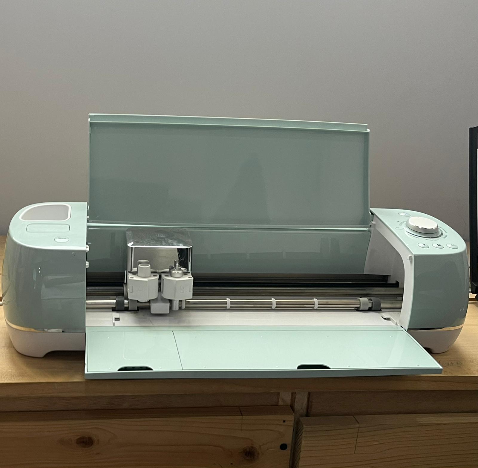
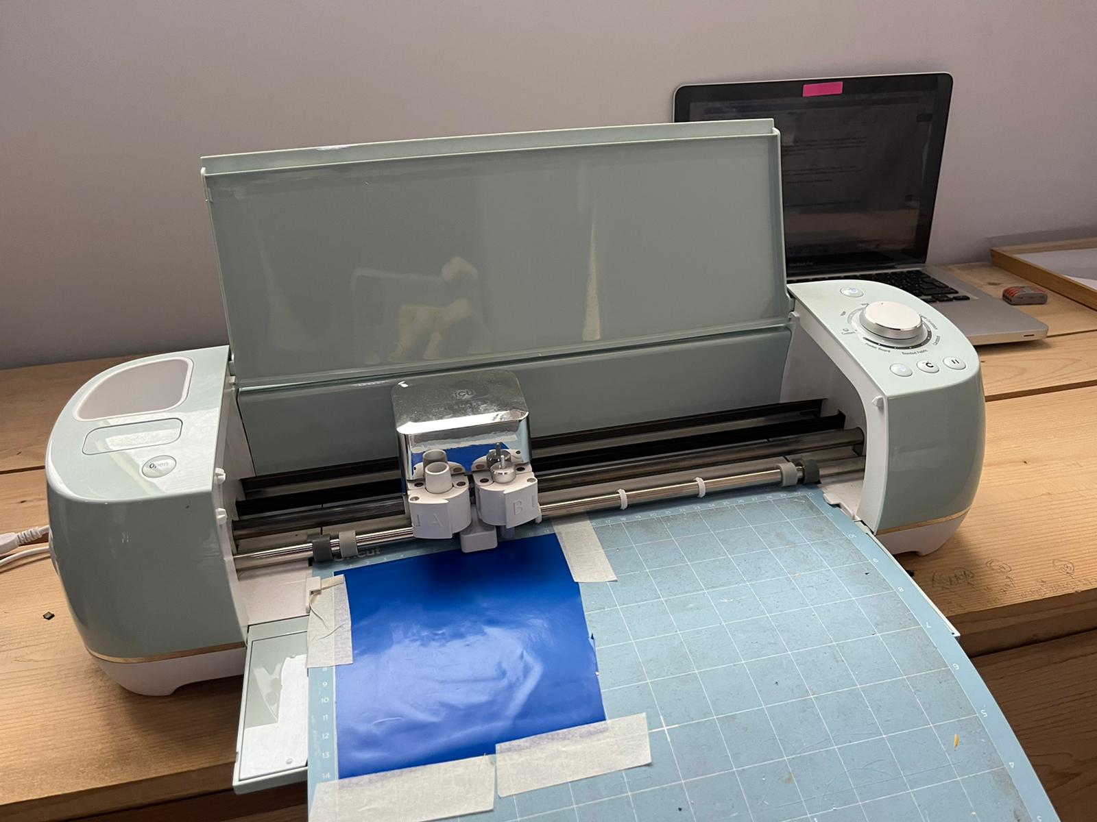
The vinyl cutter was mainly utilized here to make 2D designs into stickers that can be utilized for various purposes. The vinyl cutter uses blades with a command coming from a specific software to cut the imported design on the sticking sheet, in a neat and fashion way. The vinyl cutter looks as shown below:
Firstly, the design was taken from: Ammonia Icon
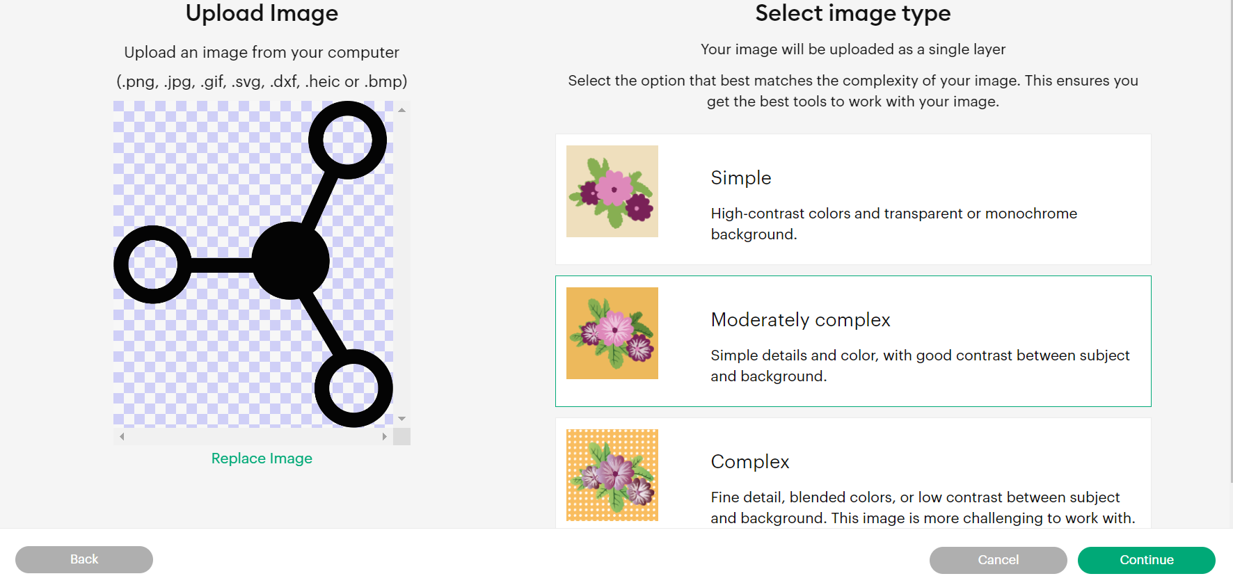
Then the image was uploaded, the option moderately complex was selected to get fine detail and blended colors. As shown below:
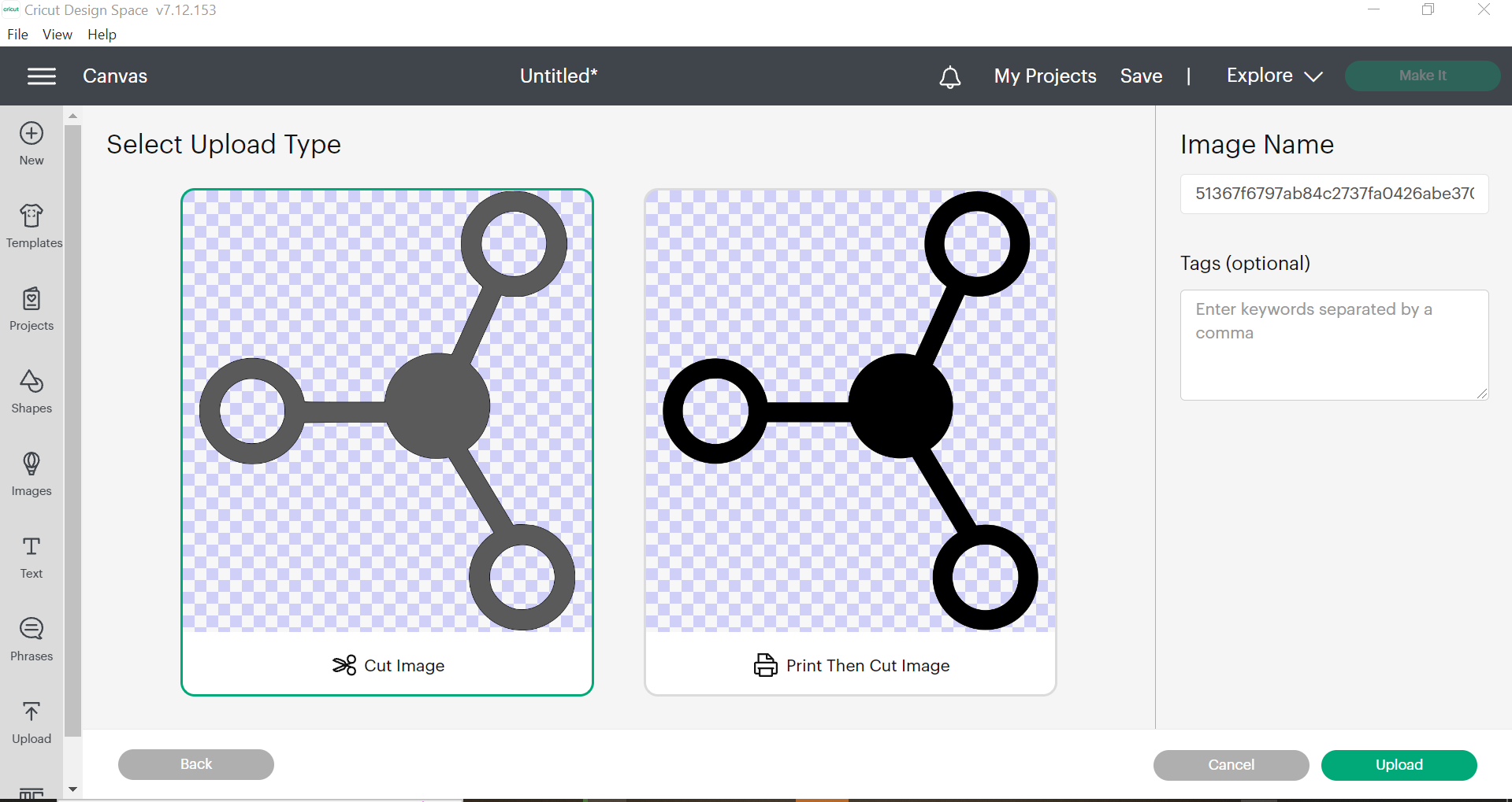
Moreover, the image was selected and the continue button was pressed to proceed. This is showcased in the figure below:
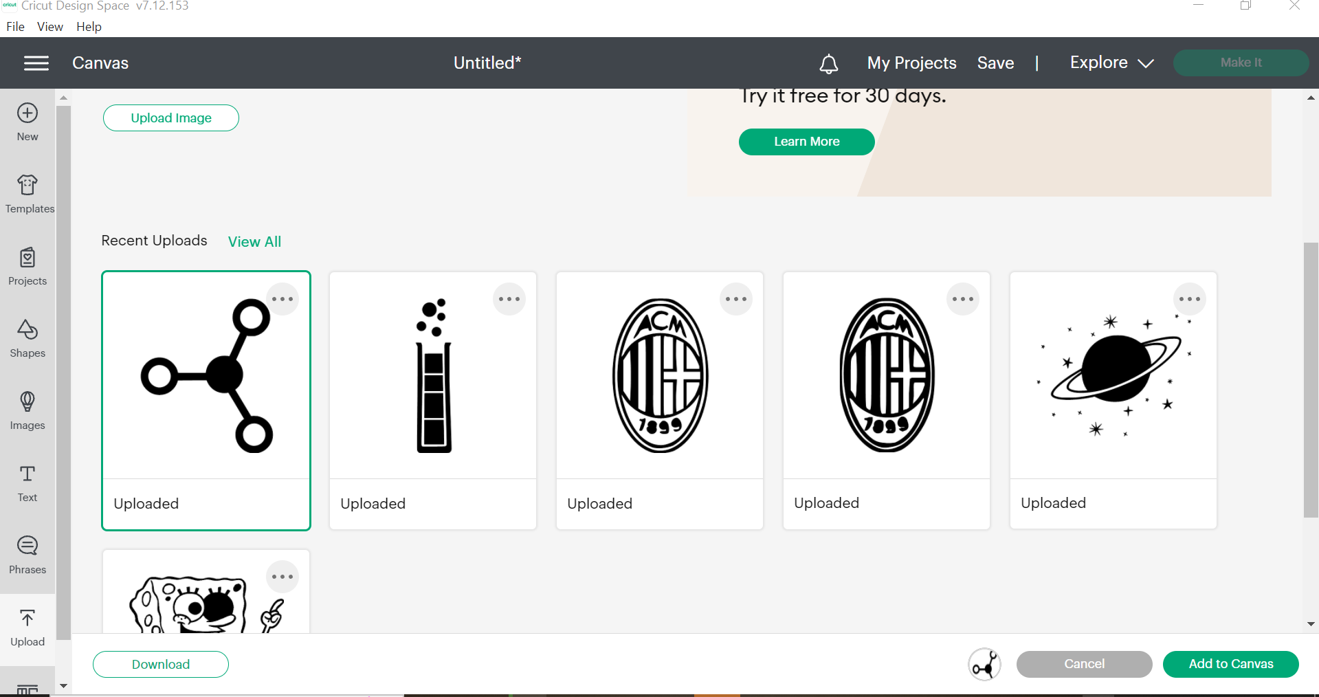
The latest design was chosen as shown below:
The “Make it” option was pressed to make the design and it would be adjusted based on the location of the sticky sheet. And, this sticker is put into the sheet used in the vinyl cutter:
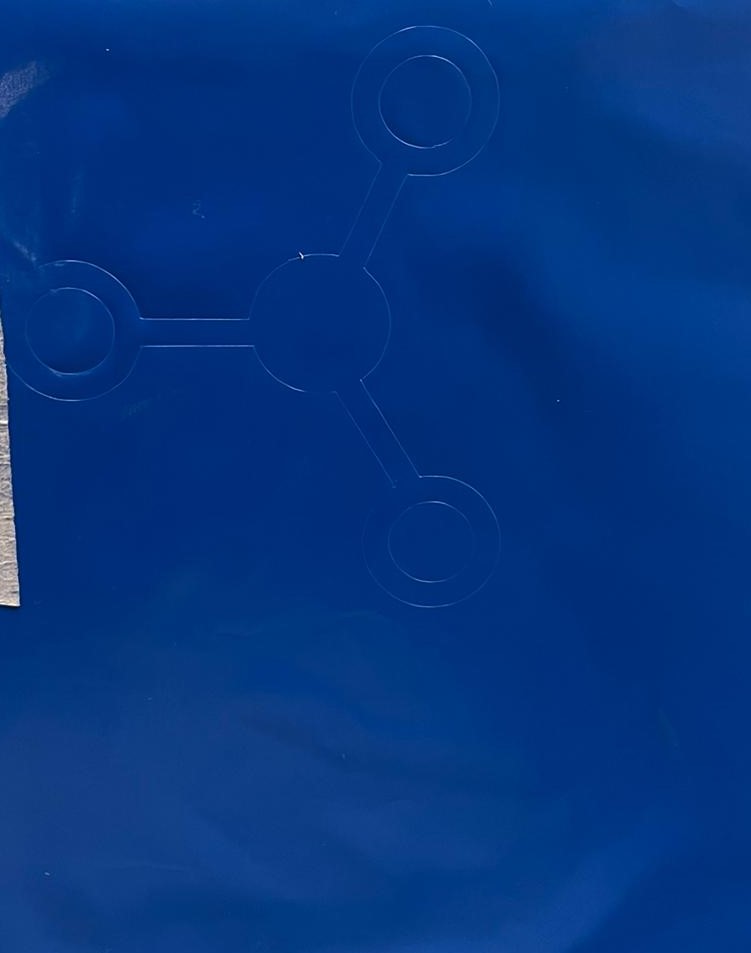
After the printing and cutting, This is how the sticker will look after removing the sticky material:
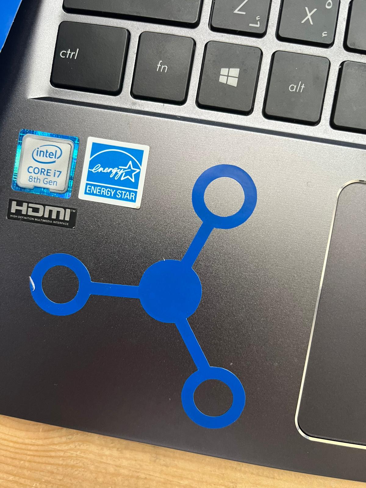
Then weeding process was implemented, in order to remove the excess material between the design. And then just leaving the designed sticker that should be pasted on the designated place (my laptop).
Final design will look as follows:
Laser Cutting
CO2 Laser Cutter:
Modern CO2 machines usually produce the laser beam in a sealed glass tube which is filled with gas, usually carbon dioxide. A high voltage flows through the tube and reacts with the gas particles, increasing their energy, in turn producing light 1.
Performing Parametric Design:
Parametric design modeling in fusion 360 is referred to as designing a model based on input and requirements. Certain parameters are controlled as input to design variable and output is obtained in the CAD design. This design primarily play with dimensions to manipulate sizes and shapes of a CAD model. Also to create geometry, parametric modelling does the difficult task easily.
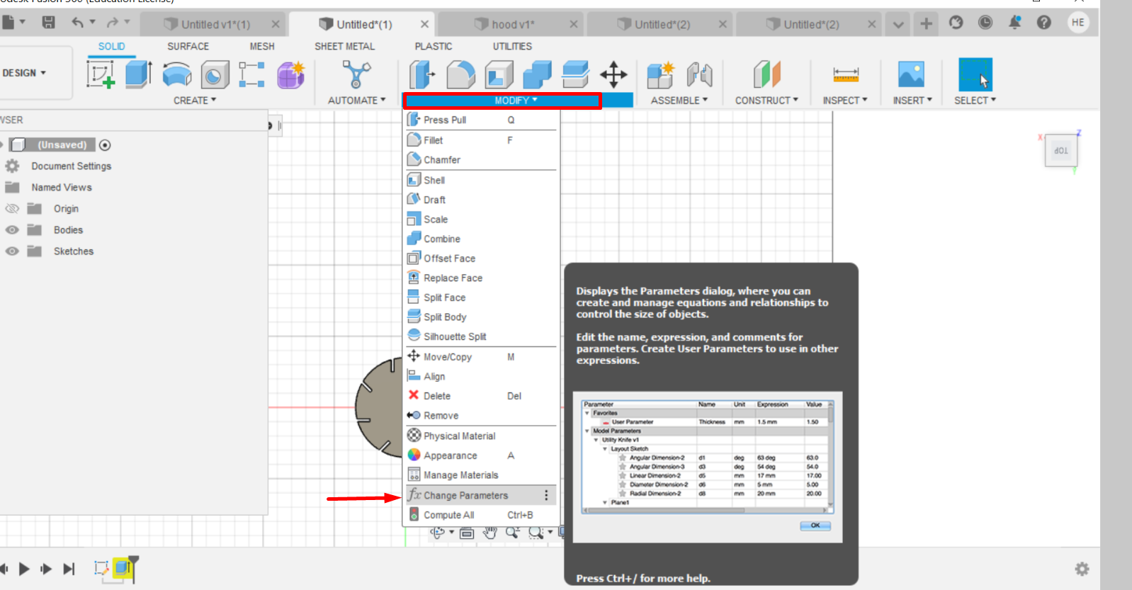
So in this design firstly, fusion 360 was opened and these dimensions (the thickness of the joint and the length or diameter) were put as parameters so that after the joint thickness test is done, we can adjust the obtained value easily. They are set as follows:
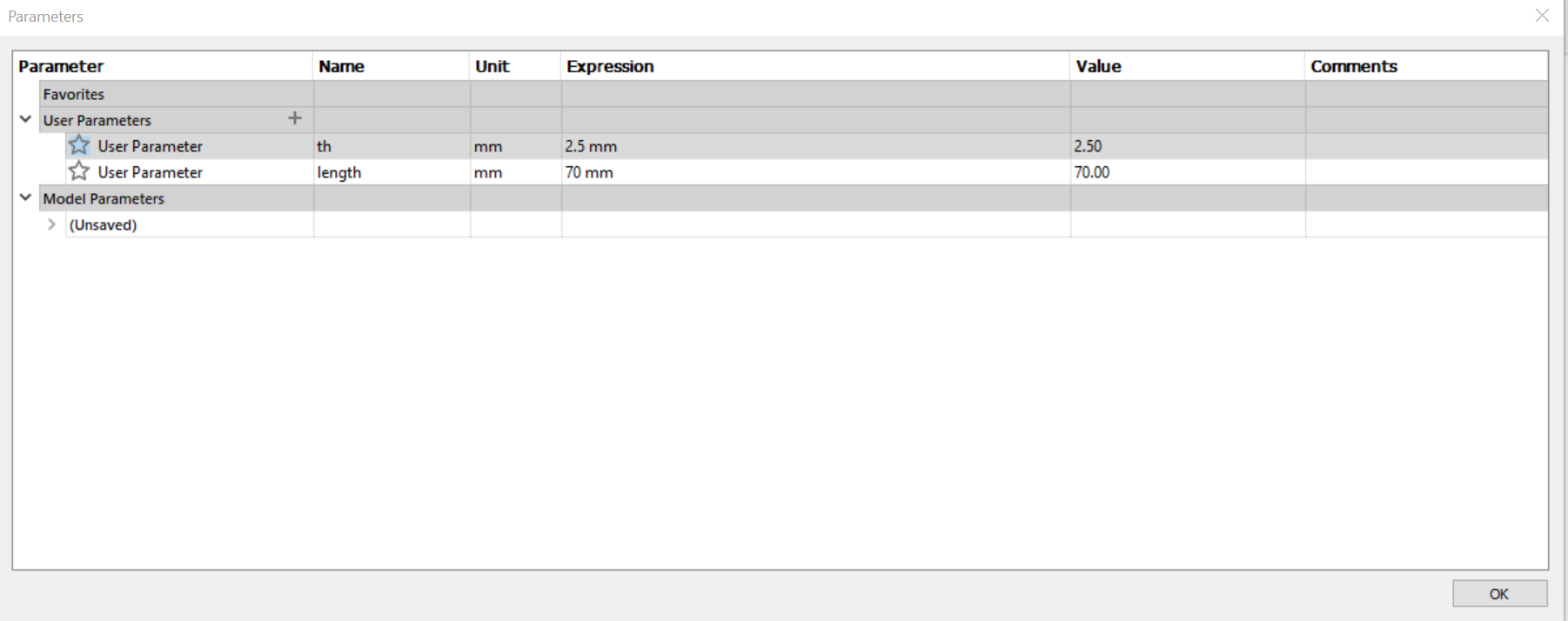
So, I fixed the thickness to be 2.5 mm and the diameter of the circle to be 70 mm.
Circle Fusion Design:
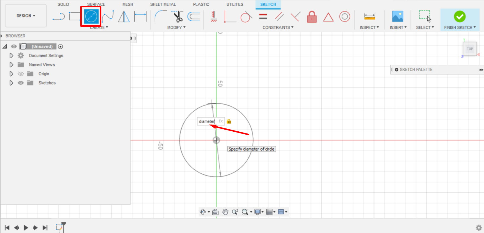
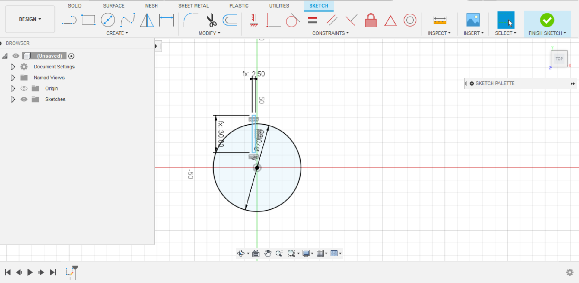
Firstly, a circle was drawn with the specified diameter as follows:
Then a triangle was placed on the inner core of the circle, as shown:
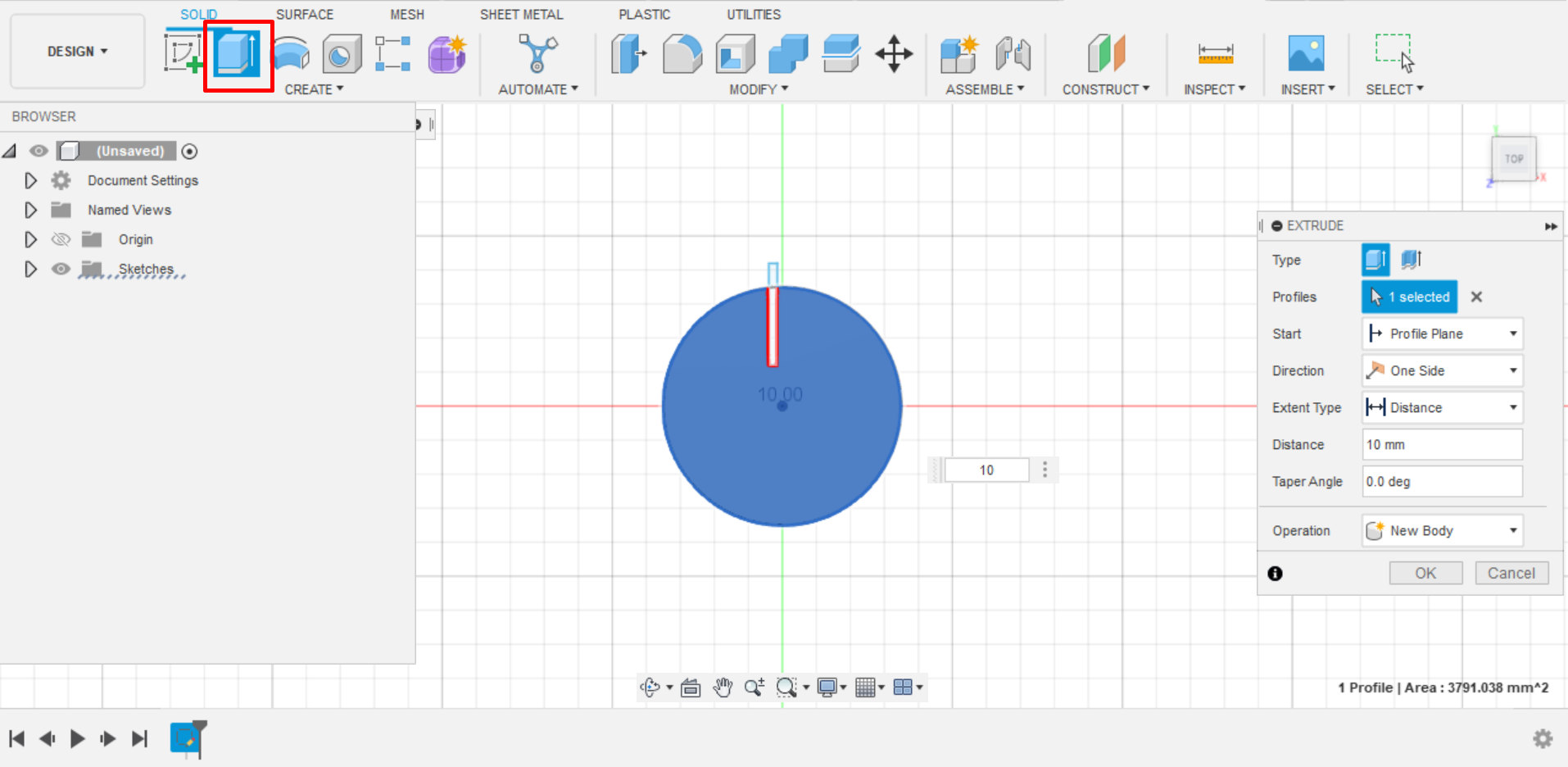
The design was extruded as to the specified thickness of the cardboard:
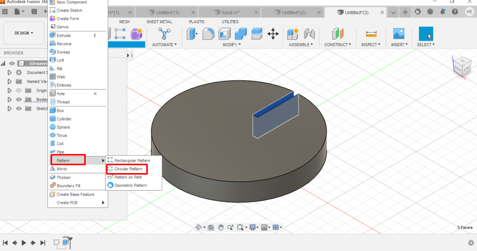
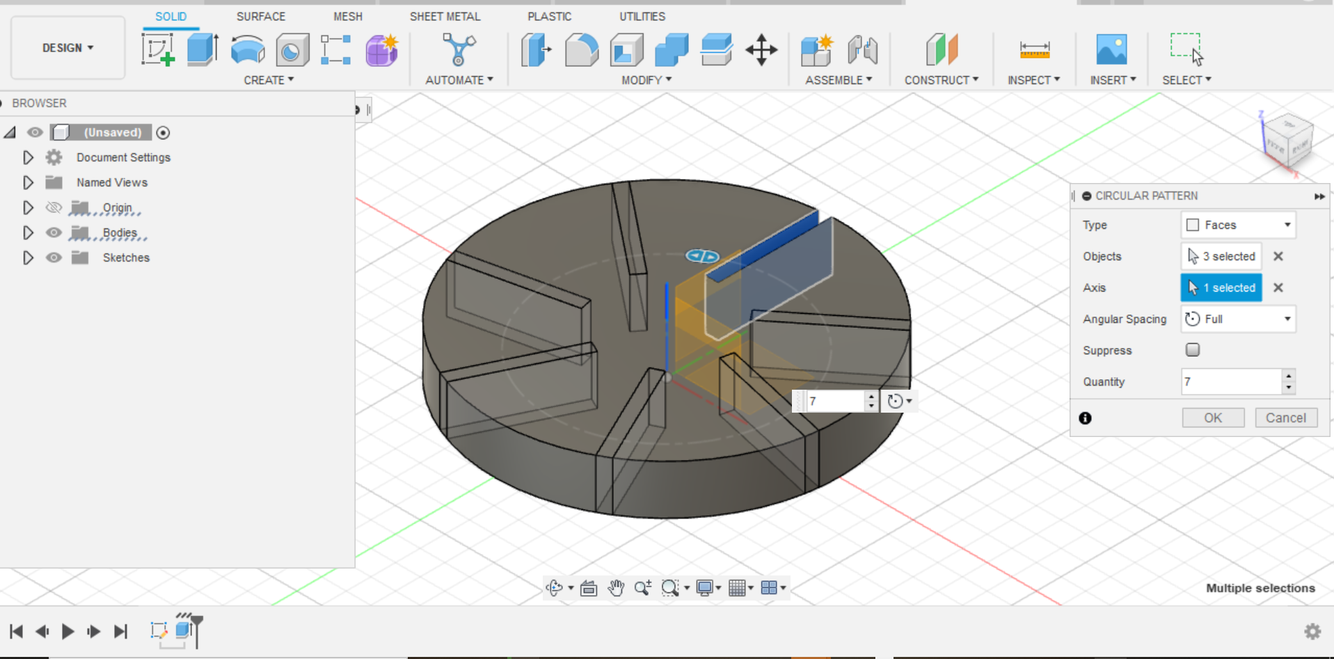
After that, Joint was selected in order to duplicate it , as shown in the following Figures:
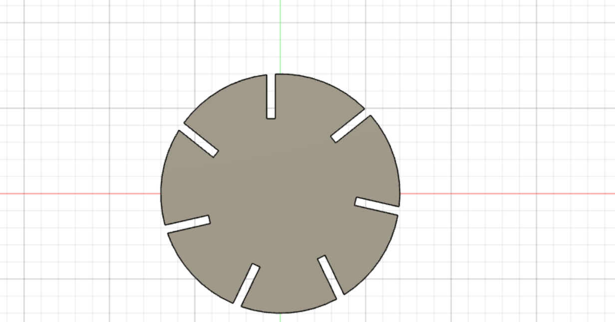
Finally, the last design will look as follows:
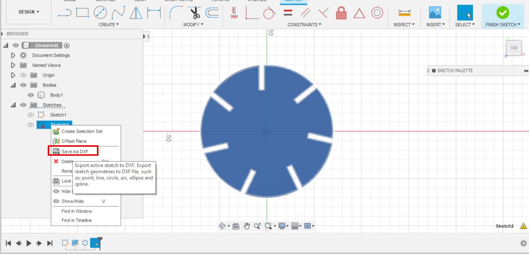
After the complete design, the design was exported as dxf file to be used in the CO2 laser machine:
CO2 laser cutter set up:
Firstly, the design was imported to RDworks program which is the program that is utilized by the laser cutter.
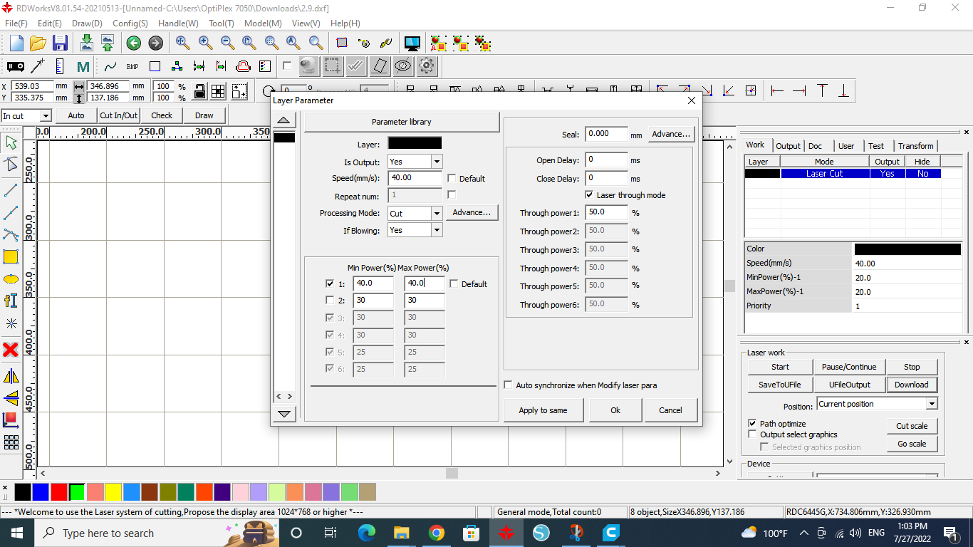
Then the parameters were adjusted in the “Layer Parameter” panel as shown:
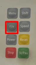
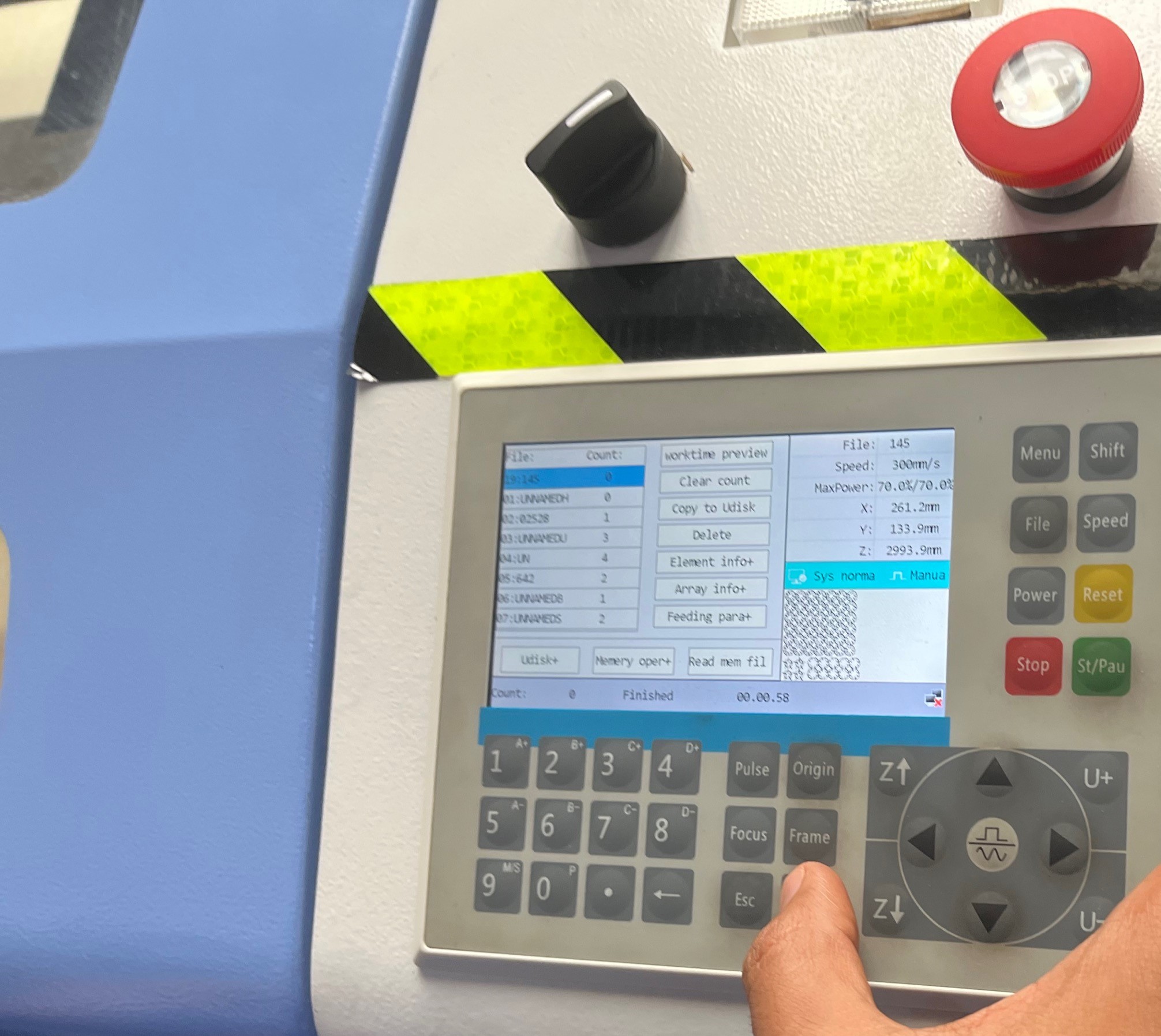
After that the file was downloaded and the cutting procedure is ready to go. Buttons “File” and “Enter” were pressed:
Also, the origin button was pressed to set the new origin and the “Frame” button was used to see how much space on the cardboard was needed during the cutting process and whether it will exceed the required space or not:
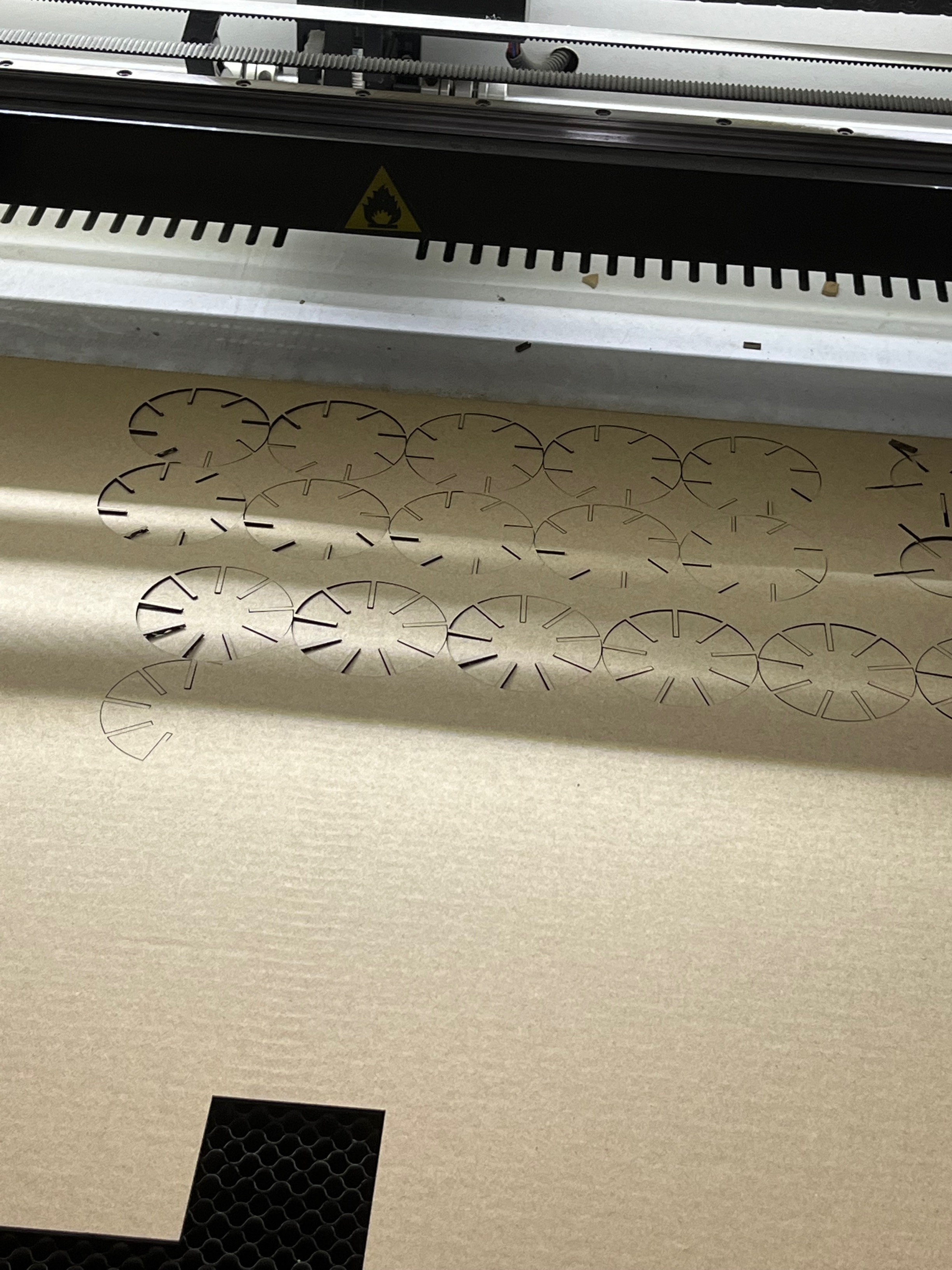
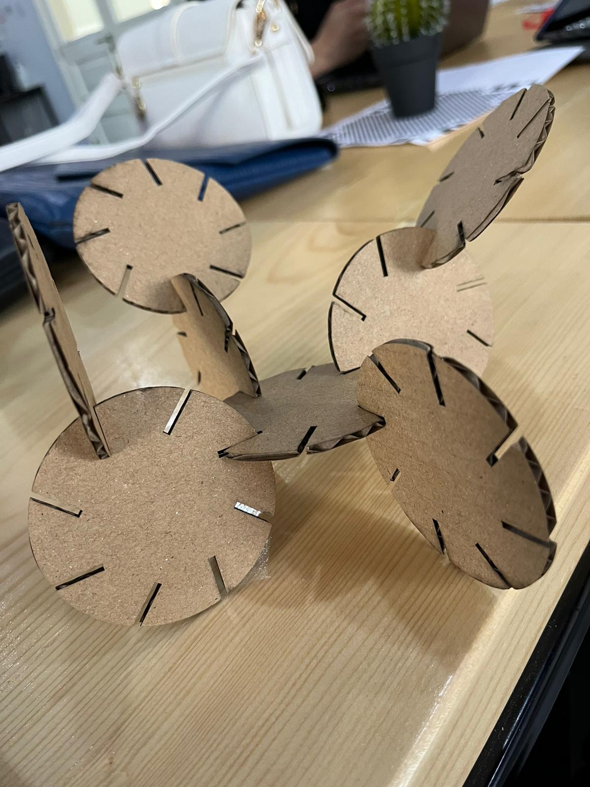
Then the design was printed and assembled as shown:
Group Assignment:
Link: Group assignment