7. Input & Output device
This weeks task encompasses utilizing input and output devices on our Microcontroller.
Analog Signal Vs. Digital Signal
An Analog signal is any continuous signal for which the time varying feature (variable) of the signal is a representation of some other time varying quantity, i.e., analogous to another time varying signal. It differs from a digital signal in terms of small fluctuations in the signal which are meaningful.
A digital signal uses discrete (discontinuous) values. By contrast, non-digital (or analog) systems use a continuous range of values to represent information. Although digital representations are discrete, the information represented can be either discrete, such as numbers or letters, or continuous, such as sounds, images, and other measurements of continuous systems.
What are input and output devices?
An input device is a hardware device that connects to your computer and sends information into the central processing unit, allowing you to interact with and control it.
An output device displays the result of the processing of raw data that is entered in the computer through an input device. There are a number of output devices that display output in different ways such as text, images, hard copies, and audio or video.
Input/output devices are usually called I/O devices. They are directly connected to an electronic module inside the systems unit called a device controller. For example, the speakers of a multimedia computer system are directly connected to a device controller called an audio card (such as a Soundblaster), which in turn is connected to the rest of the system.
Input Devices (Sensors):
Sensors are input devices that record data about the physical environment around it.
Sensors send data to a microprocessor (computer). They do not make judgements, decisions or control any output devices.
There are many types of sensors used in a variety of household, commercial and industrial applications.
Advantages of using computer sensors:
Sensors are reliable Sensors are accurate Sensors don’t get tired Sensors work well in places where humans would rather not be
Examples of sensors:
1- Temperature Sensor: Measures heat generated by an object or system. By measuring the change in heat, the sensor can detect changes in temperature.
2- Sound Sensor Measures the presence of sound.
3- Water Level Sensor
Water Level Sensor
The water level sensor is a device that measures the liquid level in a fixed container that is too high or too low. According to the method of measuring the liquid level. it can be used to detect the level of substances that can flow. Such substances include liquids, slurries, granular material and powders. Level measurements can be done inside containers or it can be the level of a river or lake.
The Water Level Sensor looks like:
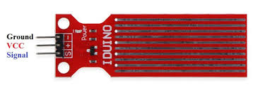
The water level sensor is super easy to use and only has 3 pins to connect.
-
S (Signal) pin is an analog output that will be connected to one of the analog inputs on your Arduino.
-
- (VCC) pin supplies power for the sensor. It is recommended to power the sensor with between 3.3V – 5V. Please note that the analog output will vary depending on what voltage is provided for the sensor.
– (GND) is a ground connection.
Water Level Sensor with Arduino
First you need to supply power to the sensor. For that you can connect the + (VCC) pin on the module to 5V on the Arduino and – (GND) pin to ground.
However, one commonly known issue with these sensors is their short lifespan when exposed to a moist environment. Having power applied to the probe constantly speeds the rate of corrosion significantly.
To overcome this, we recommend that you do not power the sensor constantly, but power it only when you take the readings.
An easy way to accomplish this is to connect the VCC pin to a digital pin of an Arduino and set it to HIGH or LOW as per your requirement. So, we’ll connect the VCC pin to the digital pin #7 of an Arduino.
Finally, connect the S (Signal) pin to the A0 ADC pin on your Arduino.
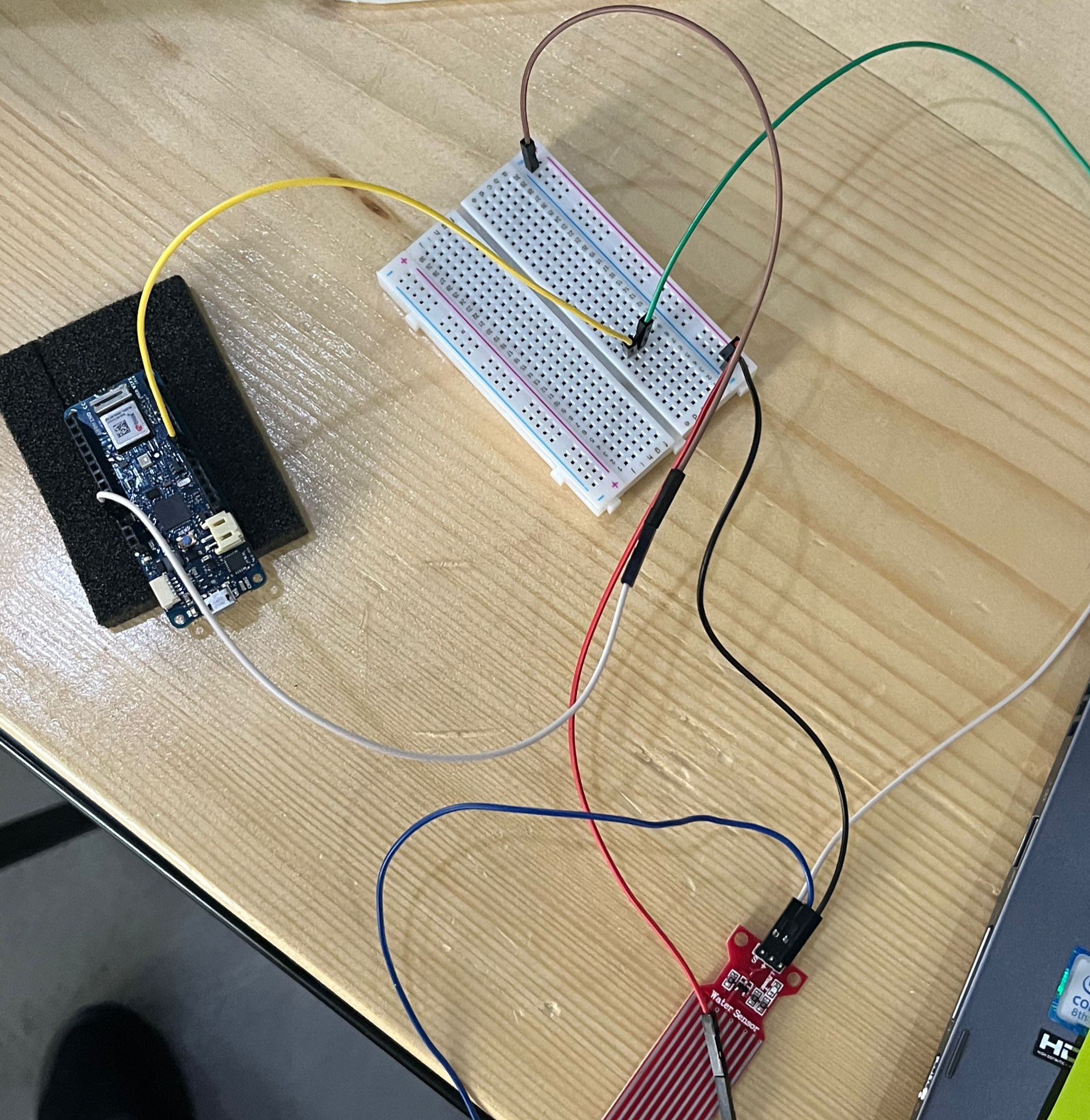
I followed the previous steps in order to connect the water level sensor with Arduino:
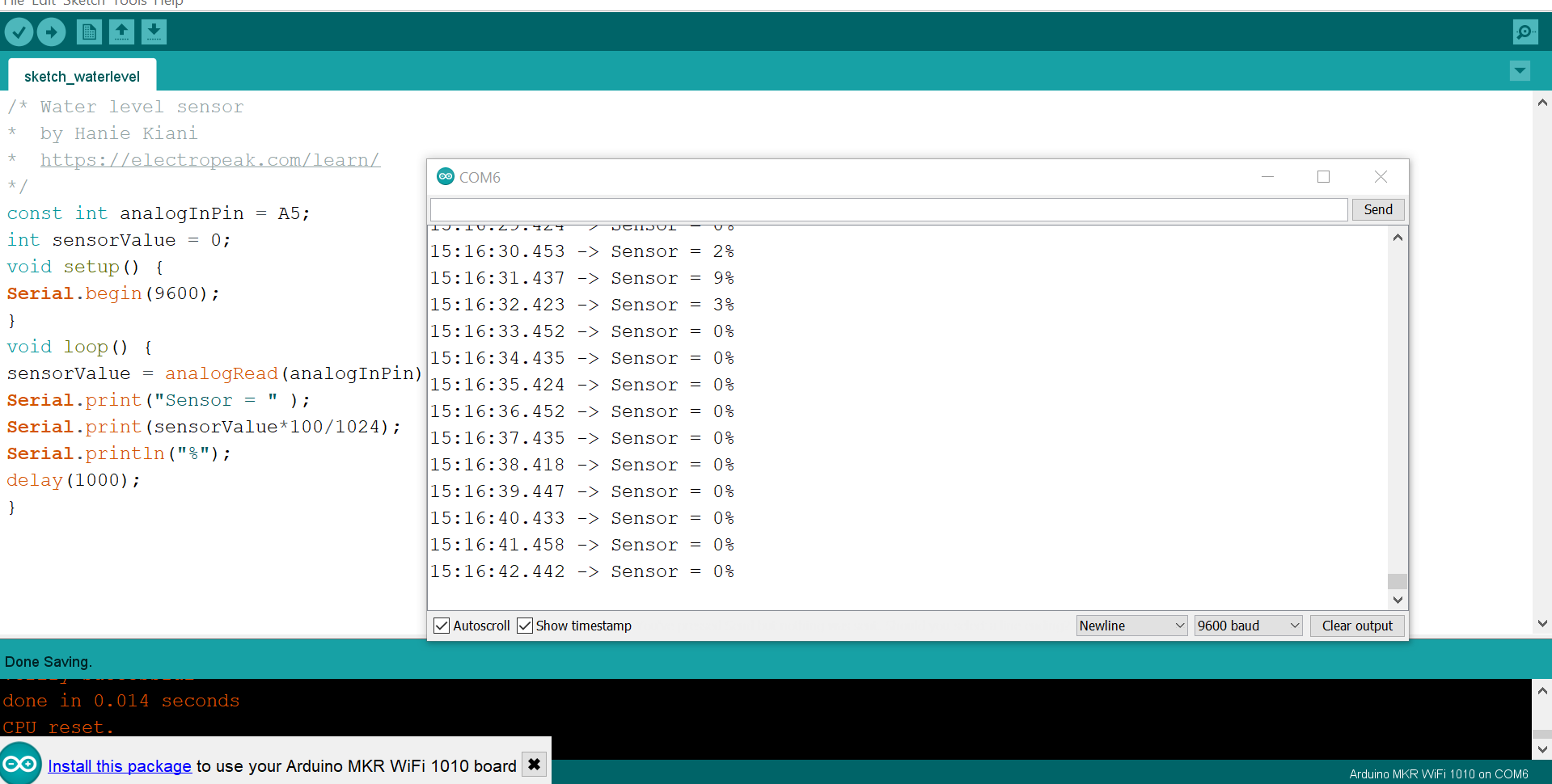
After bulding the was done, the following sketch was uploaded to Arduino:
const int analogInPin = A5;
int sensorValue = 0;
void setup() {
Serial.begin(9600);
}
void loop() {
sensorValue = analogRead(analogInPin);
Serial.print("Sensor = " );
Serial.print(sensorValue*100/1024);
Serial.println("%");
delay(1000);
}
a Serial Monitor window was opened in order to see the output from the Arduino.
First when the sensor was dry:
Moreover in order to observe its the sense for the water, I put the sensor slowly in to glass of water:
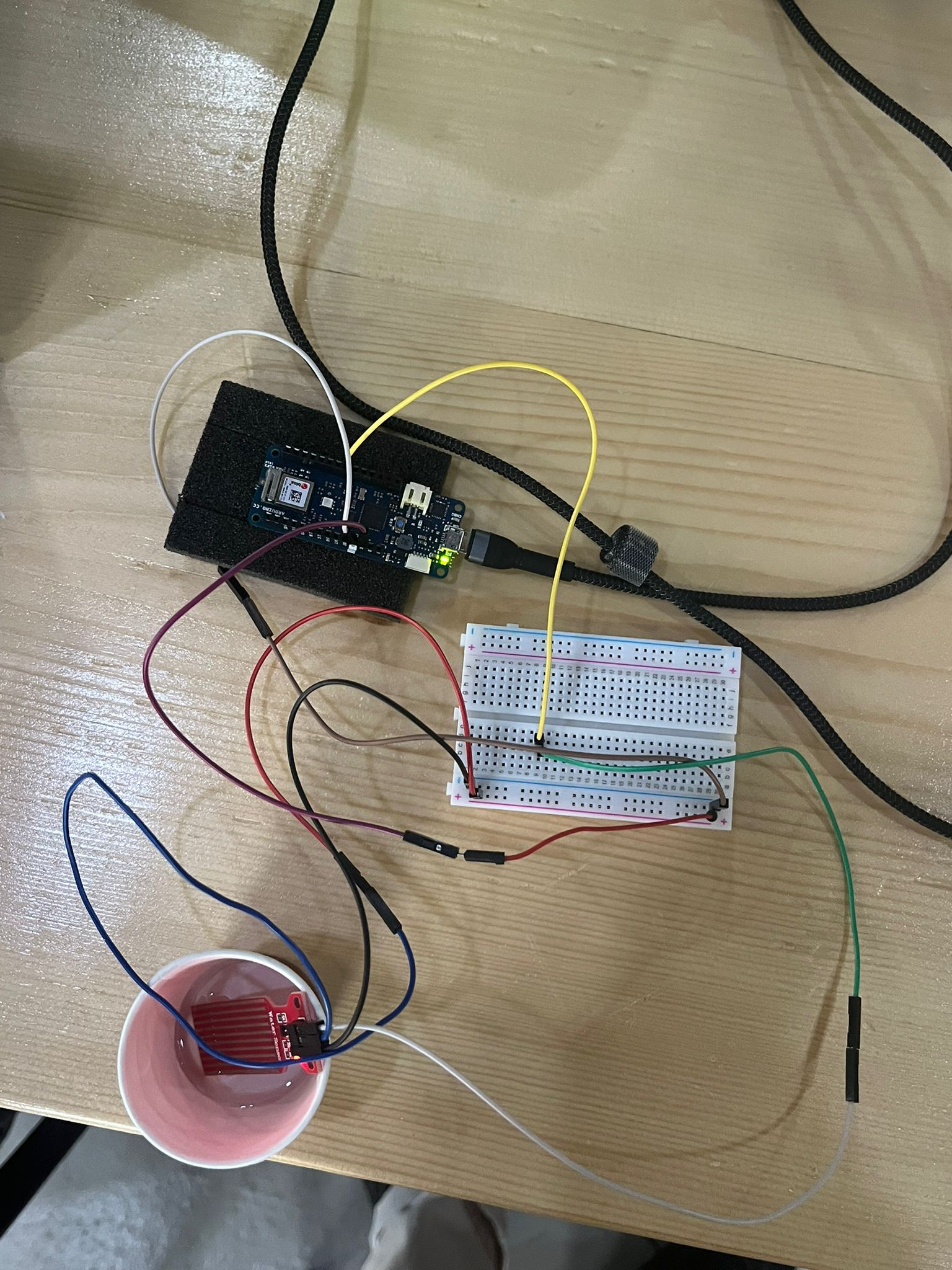
and the output was:
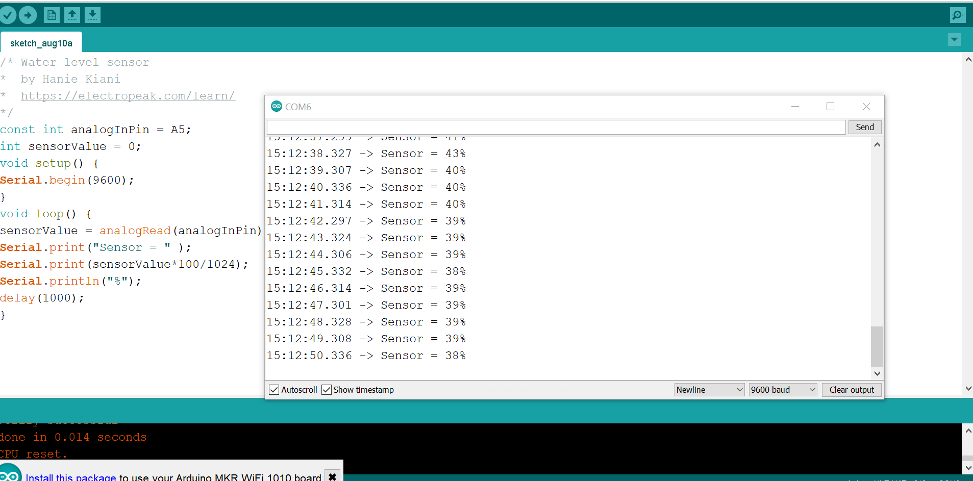
So we as shown belwo, we can easily know that when the result around or at 0% means the level of water is 0 ( there is no water on the sensor) and vice versa, when there is some % means the level of the water is that much.
Output Devices
Servomotor (Micro Servo S51)
The Servo controller is considered one of the few special output devices that work on the pulsive signal princible, sending pulsive signal to the shaft of the motor to move it based on the required degree for example 180 degree.
Mainly, this servo motor works on the servo control mechanism, where a Pulsive-Width Modulation (PWM) signal to the servo motor which consists of a sequence of repeating pulses that determine the position of the servo. The servo code and commands are very simple
Servo motors have three wires: power, ground, and signal. The power wire is typically red, and should be connected to the 5V pin on the Arduino board. The ground wire is typically black or brown and should be connected to a ground pin on the board. The signal pin is typically yellow or orange and should be connected to PWM pin on the board. In these examples, it is pin number 9.
For the Sweep example, connect the servo motor to +5V, GND and pin 9.
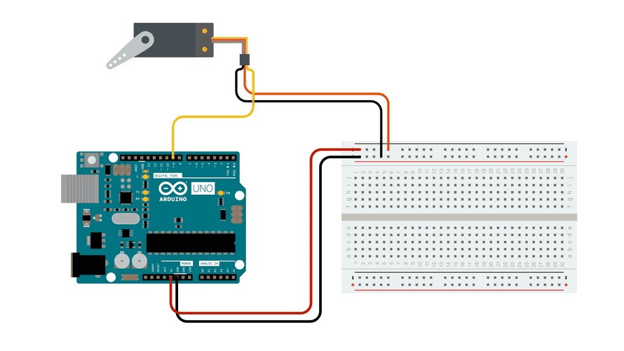
I was followed these steps in order to apply the sweep example:
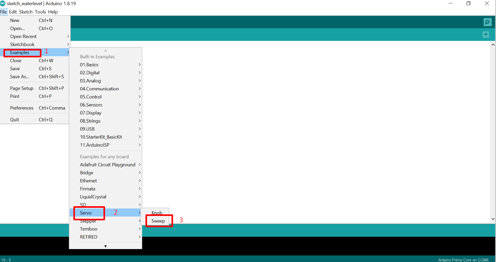
The code used is :
/* Sweep
 by BARRAGAN <http://barraganstudio.com>
 This example code is in the public domain.

 modified 8 Nov 2013
 by Scott Fitzgerald
 https://www.arduino.cc/en/Tutorial/LibraryExamples/Sweep
*/

#include <Servo.h>

Servo myservo;  // create servo object to control a servo
// twelve servo objects can be created on most boards

int pos = 0;    // variable to store the servo position

void setup() {
  myservo.attach(9);  // attaches the servo on pin 9 to the servo object
}

void loop() {
  for (pos = 0; pos <= 180; pos += 1) { // goes from 0 degrees to 180 degrees
    // in steps of 1 degree
    myservo.write(pos);              // tell servo to go to position in variable 'pos'
    delay(15);                       // waits 15 ms for the servo to reach the position
  }
  for (pos = 180; pos >= 0; pos -= 1) { // goes from 180 degrees to 0 degrees
    myservo.write(pos);              // tell servo to go to position in variable 'pos'
    delay(15);                       // waits 15 ms for the servo to reach the position
  }
}
when I uploadeed the code, this is what I got as a result:
RGB Full Color LED SMD Module
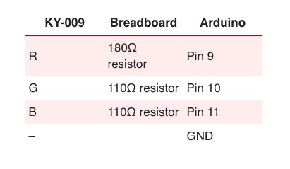
RGB full color LED Module KY-009 for Arduino, emits a range of colors by mixing red, green and blue. The amount of each primary color is adjusted using PWM.
Connection Diagram:
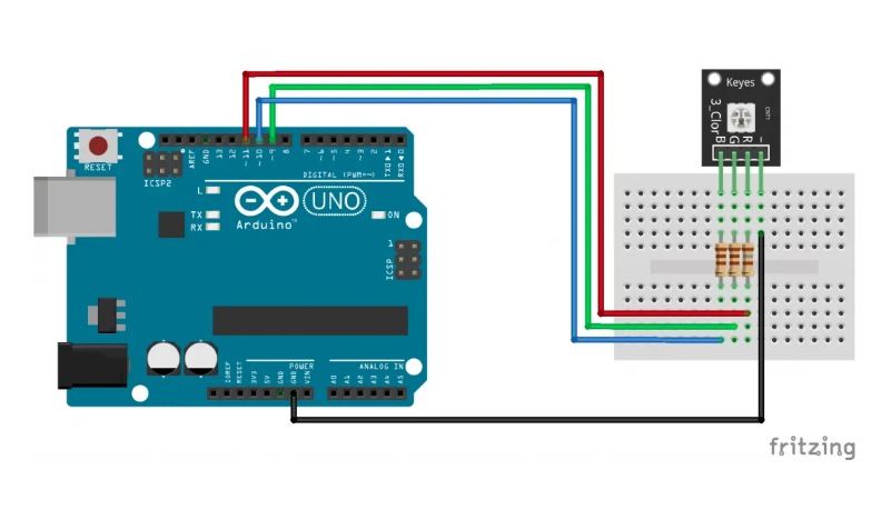
The following Arduino sketch will cycle through various colors by changing the PWM value on each of the three primary colors.
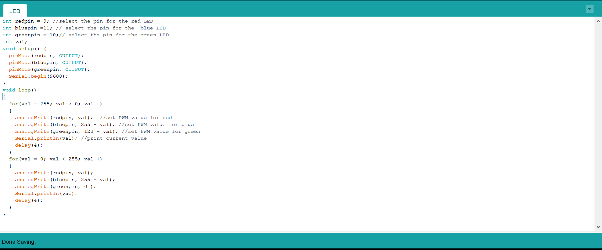
int redpin = 9; //select the pin for the red LED
int bluepin =11; // select the pin for the  blue LED
int greenpin = 10;// select the pin for the green LED
int val;
void setup() {
  pinMode(redpin, OUTPUT);
  pinMode(bluepin, OUTPUT);
  pinMode(greenpin, OUTPUT);
  Serial.begin(9600);
}
void loop()
{
  for(val = 255; val > 0; val--)
  {
    analogWrite(redpin, val);  //set PWM value for red
    analogWrite(bluepin, 255 - val); //set PWM value for blue
    analogWrite(greenpin, 128 - val); //set PWM value for green
    Serial.println(val); //print current value
    delay(4);
  }
  for(val = 0; val < 255; val++)
  {
    analogWrite(redpin, val);
    analogWrite(bluepin, 255 - val);
    analogWrite(greenpin, 0 );
    Serial.println(val);
    delay(4);
  }
}
Combining Input and Output Devices
In order to understand the input and output devices more, my colleague Yaqeen and I were tried to link the servo position to the temperature & humidity sensor in order to further understand the working princible. However, since I did not use the temperature & humidity sensor in the input task previously, I will explain the importatnt information here.
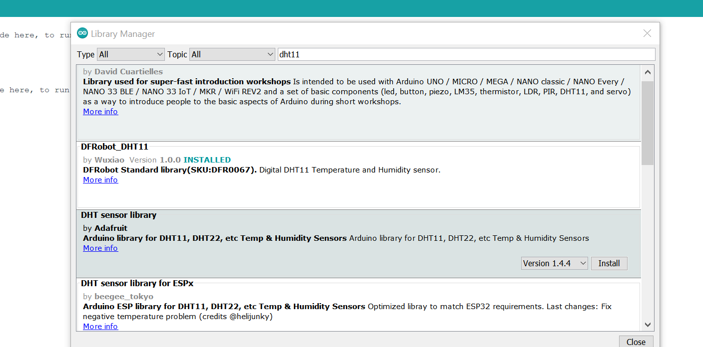
The DHT11 is a basic, ultra low-cost digital temperature and humidity sensor. It uses a capacitive humidity sensor and a thermistor to measure the surrounding air, and spits out a digital signal on the data pin (no analog input pins needed)
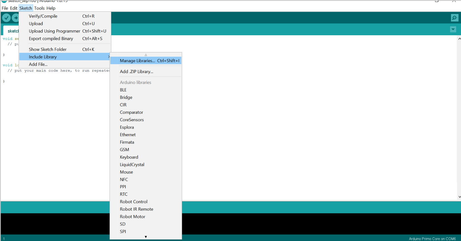
First, I downloaded the library of the Arduino:
The code used in this task is shown below which would be explained later:
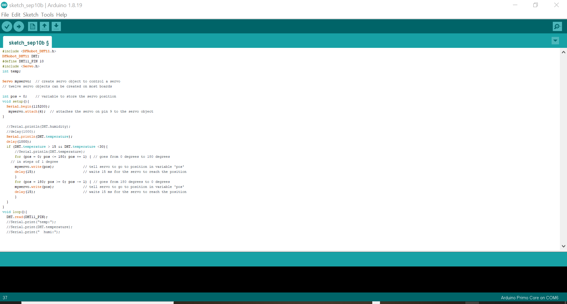
#include <DFRobot_DHT11.h>
DFRobot_DHT11 DHT;
#define DHT11_PIN 10
#include <Servo.h>
int temp;

Servo myservo;  // create servo object to control a servo
// twelve servo objects can be created on most boards

int pos = 0;    // variable to store the servo position
void setup(){
  Serial.begin(115200);
   myservo.attach(9);  // attaches the servo on pin 9 to the servo object
}

void loop(){
  DHT.read(DHT11_PIN);
  //Serial.print("temp:");
  //Serial.print(DHT.temperature);
  //Serial.print("  humi:");
  //Serial.println(DHT.humidity);
  //delay(1000);
  Serial.println(DHT.temperature);
  delay(1000);
  if (DHT.temperature > 15 && DHT.temperature <30){
      //Serial.println(DHT.temperature);
      for (pos = 0; pos <= 180; pos += 1) { // goes from 0 degrees to 180 degrees
    // in steps of 1 degree
      myservo.write(pos);              // tell servo to go to position in variable 'pos'
      delay(15);                       // waits 15 ms for the servo to reach the position
      }
      for (pos = 180; pos >= 0; pos -= 1) { // goes from 180 degrees to 0 degrees
      myservo.write(pos);              // tell servo to go to position in variable 'pos'
      delay(15);                       // waits 15 ms for the servo to reach the position
      }
  }
}
it can be seen in the picture that, the servo library is added to the DHT11 code through the #include , servo is also defined. The Servo is defined to read from the 9th pin as by the (servo.attach (9)). An if statement is used for the servo motor to move, if the temperature goes beyond a specific threshold. The servo motor is set to move 180 degrees by the command (servo.write(angle)). Finally, some delays were put in order to wait partially between each conducted measurement.
The following shows the way both the temperatue and the servo motor connection to the microcontroller in the breadboard:

The following videos illustrate the achieved outcome of the conducted procedure:
In the second video, Dr.salman was helped us to heat the sensor in order to increase the tempreature more than the spicifed range. And it is shown that the servo stopped when the tempreature became higher than the range.
References
- Analog Vs. Digital
- Input
- Output devices
- Sensors
- Water Level Sensor
- Servo Motor
- RGB
- DHT11 temperature-humidity sensor