6. Large format CNC (computer controlled Machining)
This week I will be designing a model and then construct it using CNC machining, to begin with, a box for books is designed using Fusion 360 which is then extruded as dxf files to be translated to the motor directions to guide the CNC machine. After that, a test to validate and check the variation in the feed rate, rotational speed and depth is done to check the operating conditions for the CNC machine on a wooden plate. Finally, the dxf files were transferred to the CNC programs which are then treated to yield the satisfactory design into existence by following the CNC program guide to build the demonstrated design. Before dealing with the CNC machine there was a safety session to have a background about the machine and how it might harm the users if not used in a proper way without any precautions.
What is a CNC machine?
CNC Machining is a manufacturing process where computers run programs that control how the machines will manufacture parts. These CNC Programs using CNC Software can control everything from the motions the machine makes to spindle speed, turning coolant on or off, and much more. The computer language used to program CNC Machines is called “G-Code”.
The CNC meaning can be defined as a process in which pre-programmed computer software dictates the movement of factory machinery and tools. As a result, manufacturers can produce parts in less time, reduce waste and eliminate the risk of human error.
Fusion 360 Design
Fusion 360 software was used to design a 3D box to be fabricated using CNC.
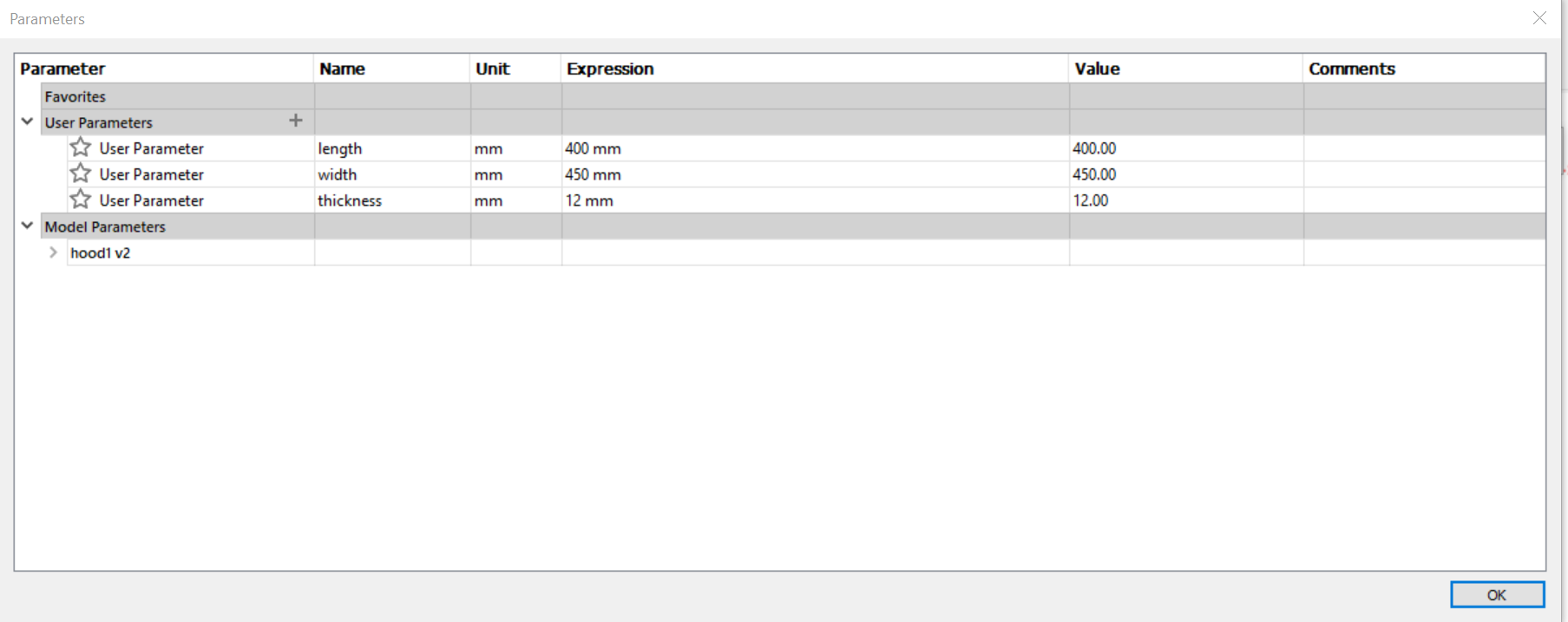
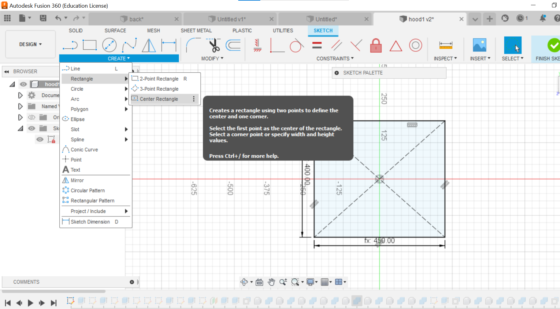
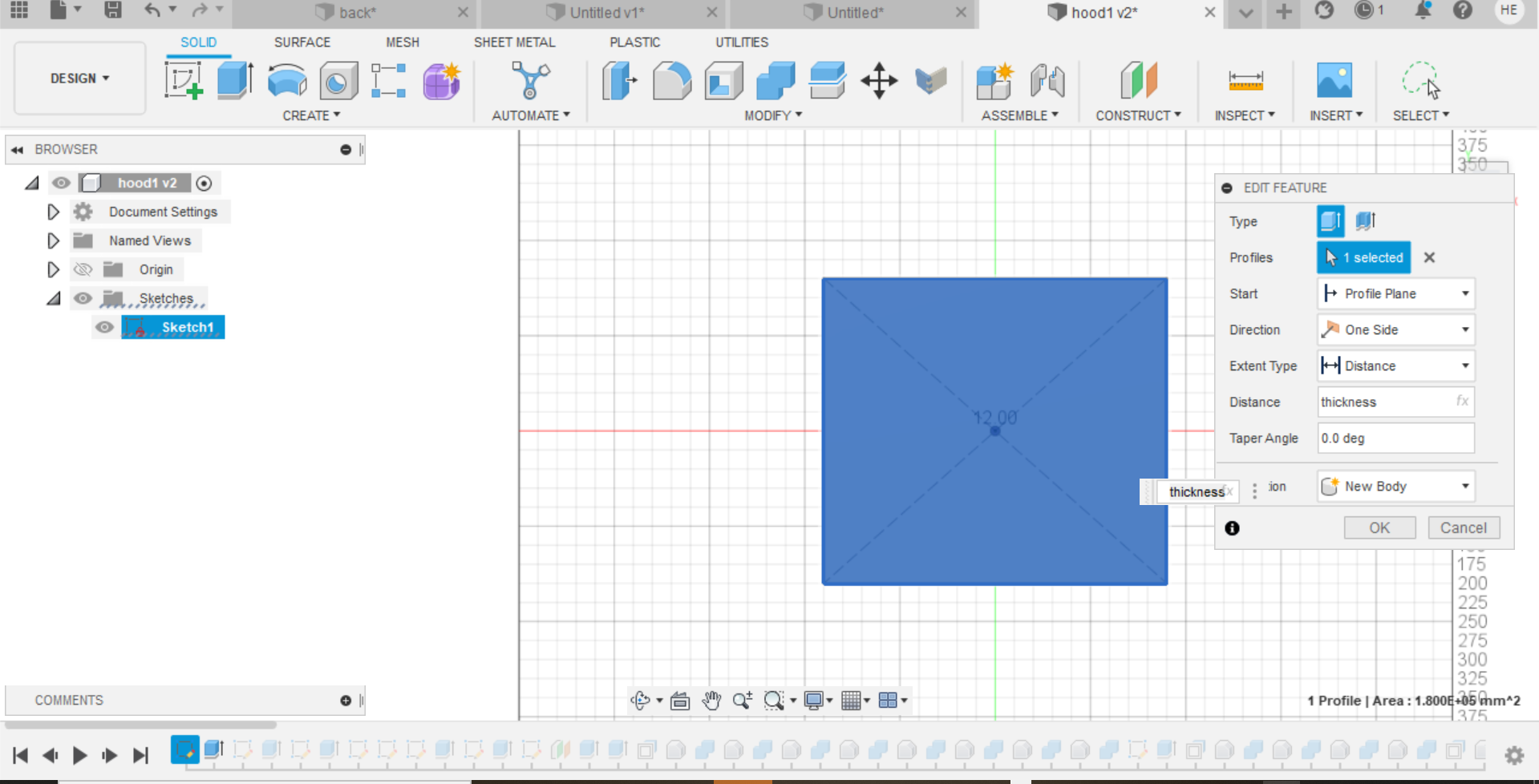
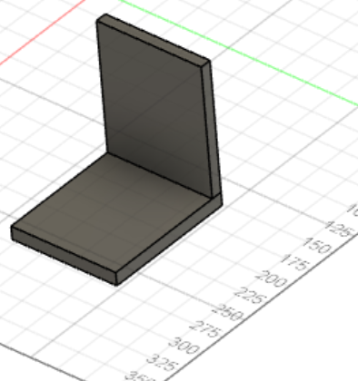
The design was started by the designing the base of 450x400 cm, with a thickness of 12 mm. a rectangular shape was used to design this part, from the sketch. Then, it was extruded by 12 mm to put the thickness, As shown below:
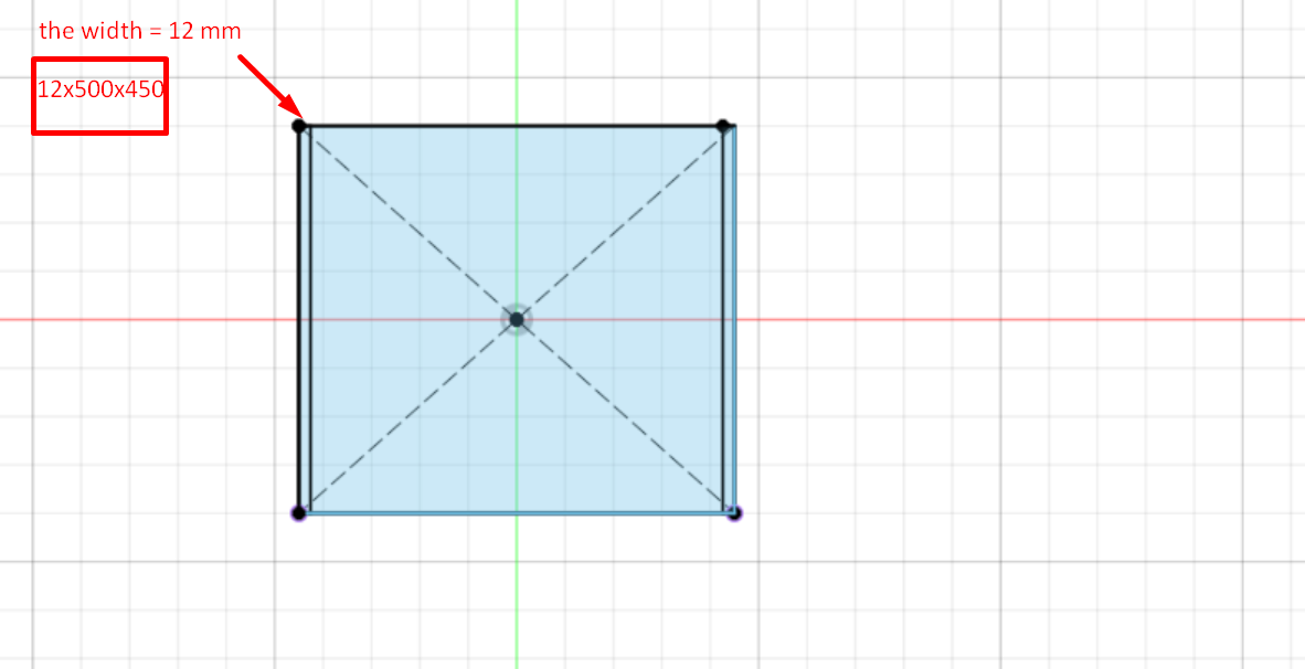
After that, another sketch was created on the perpendicular plane for the left face of the box:
However, in this face: the width diemnsion will be the (thickness) and it will be extrude for 500 mm which will be the (height) of the face:
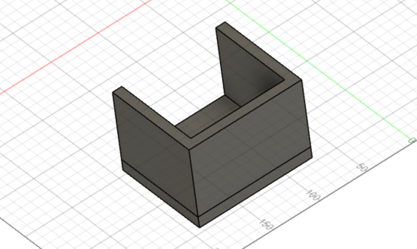
Similarly, the other faces of the box were sketched and extruded
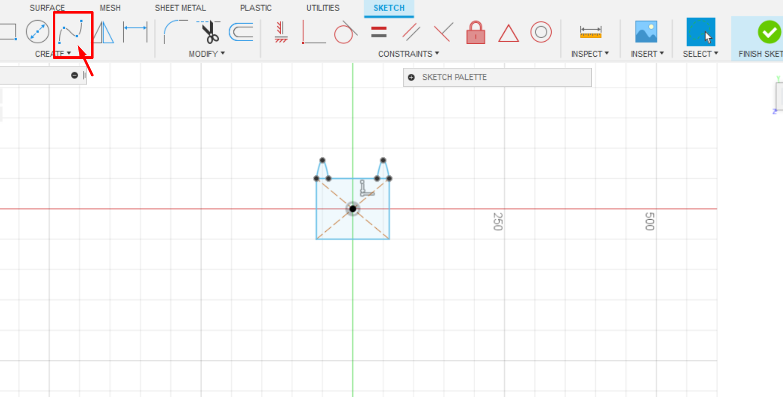
For the front face I used (point spline tool) to draw cat’s ears in order to be something that attract the kids:
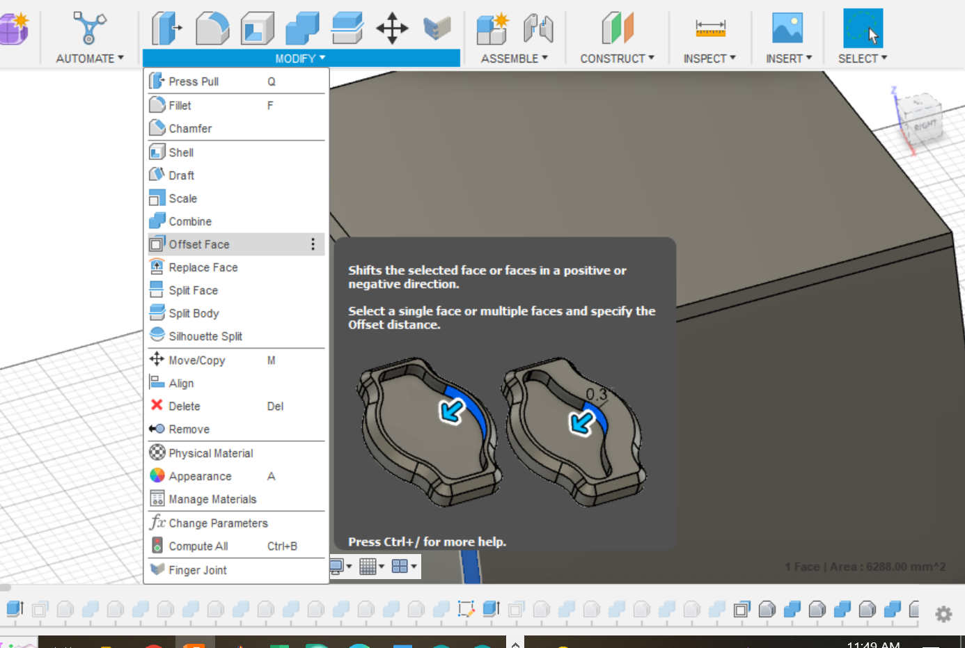
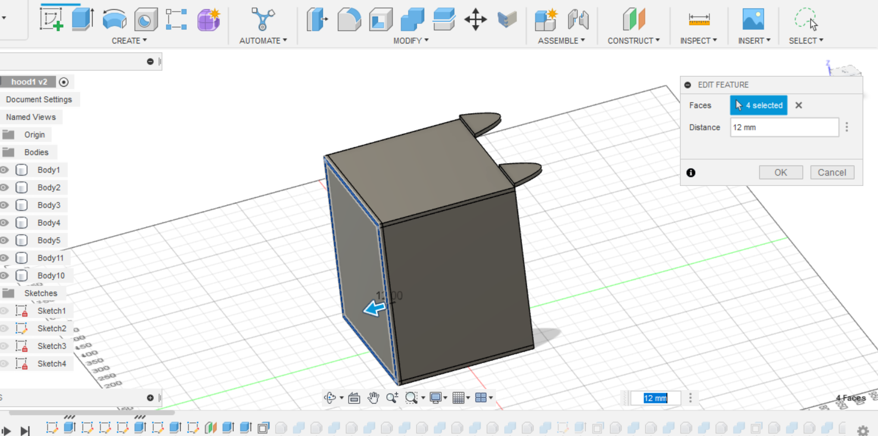
For the joints, finger joint was used in my design. But first we have to overlab the all edges between each two faces of the box by 12 mm in order to create the joints as shown below:
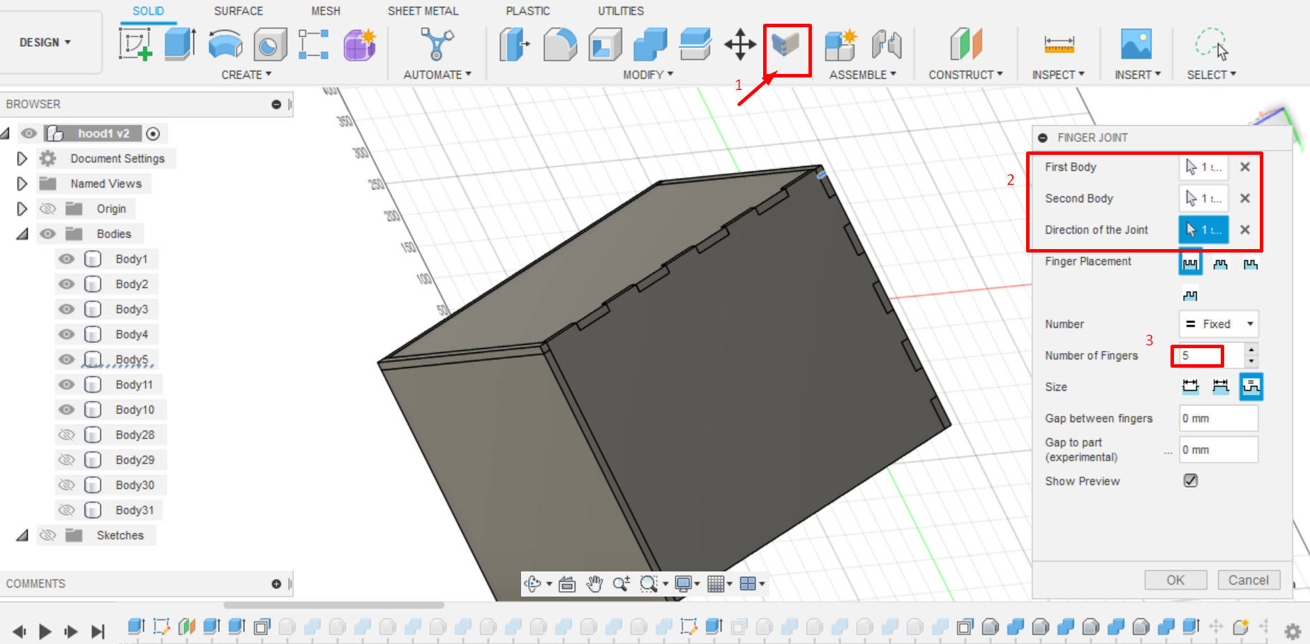
We have also to download (an add-in) tool for Fusion 360 where this will help to creating the joints easily. I downloaded from this link
After that, I made the joints as follows: 1- select the Finger joint tool 2- select the two bodies anf the direction of the joints 3- select the number of joints that you want
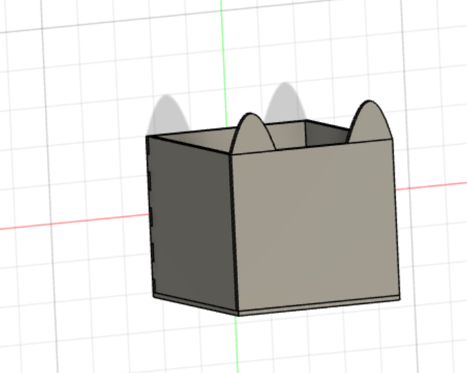
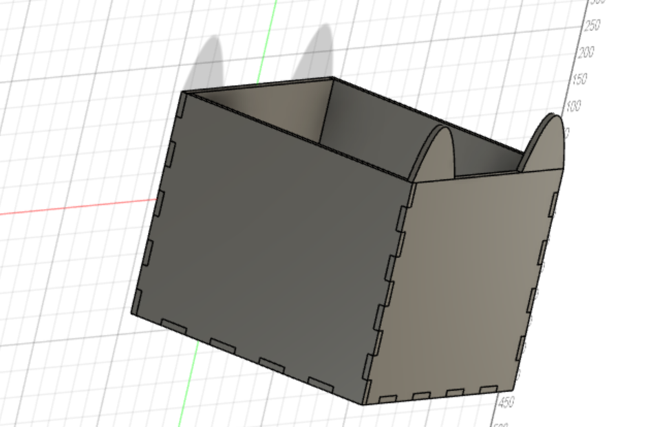
the final results will be as:
Constructing the design by CNC machine
First of all, after completing the design, the design was exported as an dxf file to be translated so that the motor of the CNC machine understands it.
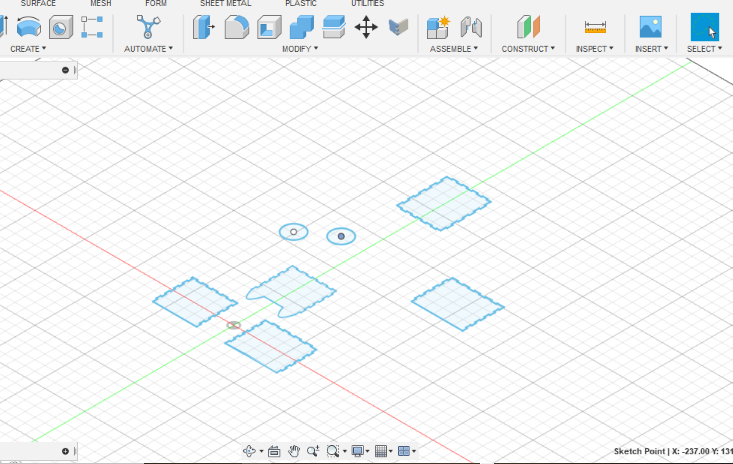
the faces of the box were all exported as a dxf files through making a sketch on each of the stated parts and then exporting them:
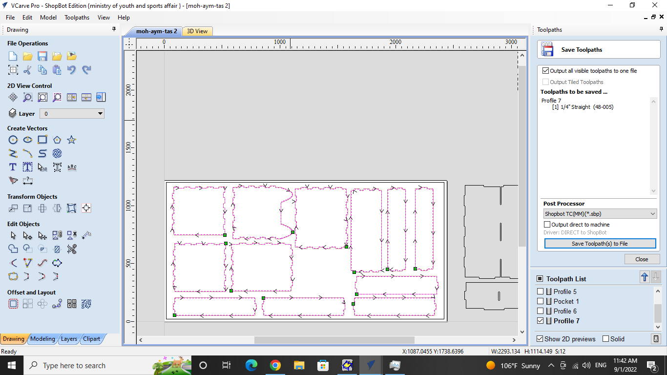
After that, they were transferred to the laptop connected to the CNC machine to begin the procedure of cutting the pieces using VCARVE program. we use this program because as I mentioned preivously, The CNC machine does not understand the 3D design that was done in Fusion 360, so this program was utilized as a translator for the CNC machine to understand the design
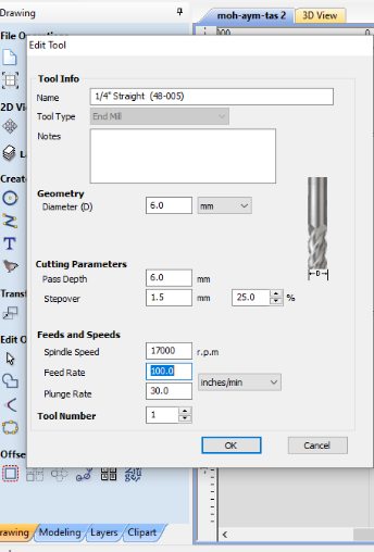
2- The following command permits various adjustments to the tool path , like the feed rate, rotational speed. Where the speed is 17000 revolutions per minute and The feed Rate was set to 100 as shownn below:
3- In order to avoid this issue (inner corners can never be more sharp than the diameter of the cutting tool) :
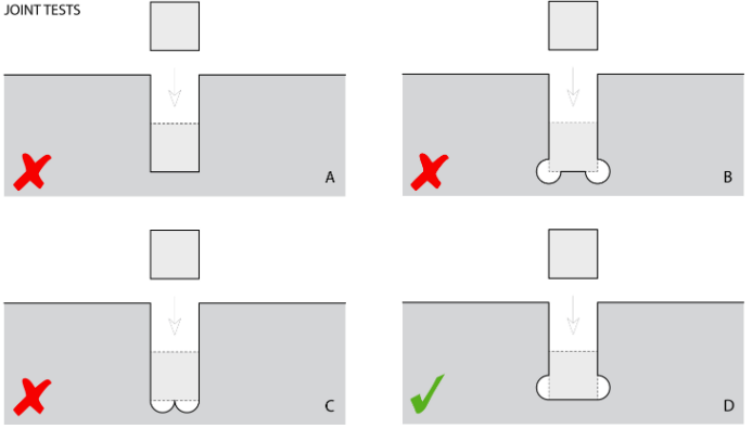
we have to add dog bone to the joints
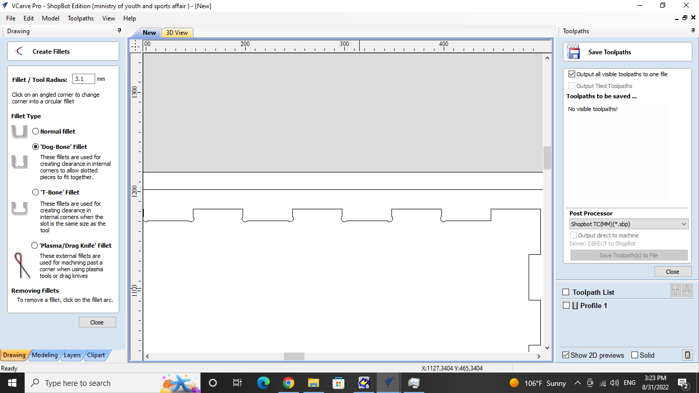
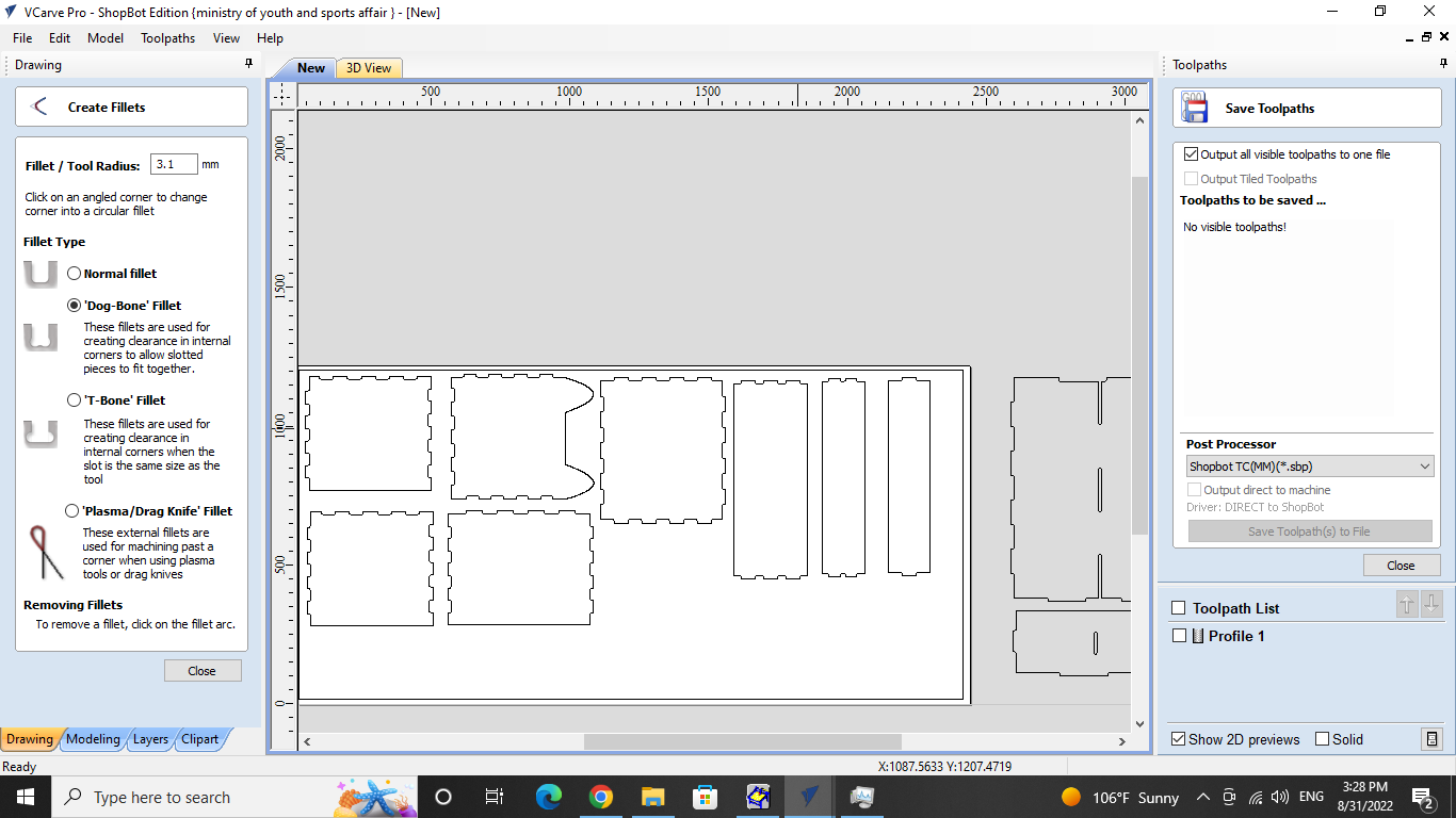
Cut depth was set to 13 mm because the thickness of the plywood material is 12 mm.
Finally, we saved the all changes and the Figure below showcases the control panel for the CNC machine, where the X, Y and Z axis dimensions were set and it also was utilized to move the bit in the intended direction.


Then, there will be some steps we have to do before start to cut:
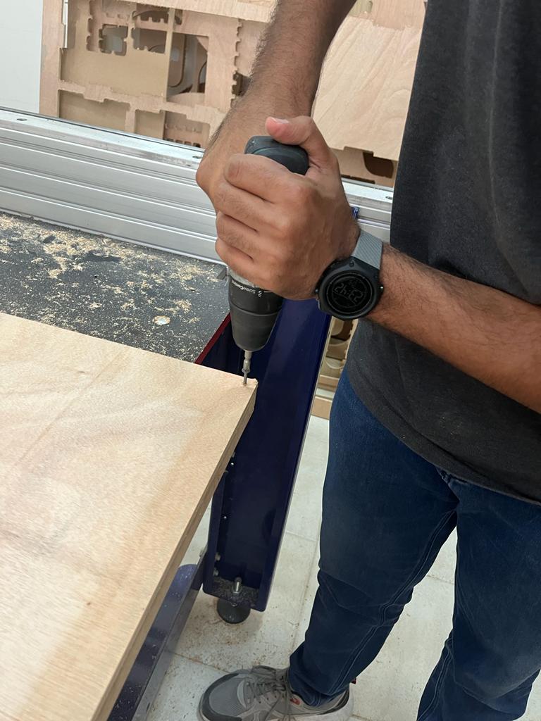
1- we have to fix the plywood on the CNC mashine to make sure that the plywood dont move when the mashine work:
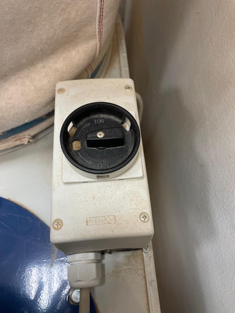
2- Safety goggles should be worn at all times when inside the room and a sufficient space from the machine should be taken to avoid any accidents.
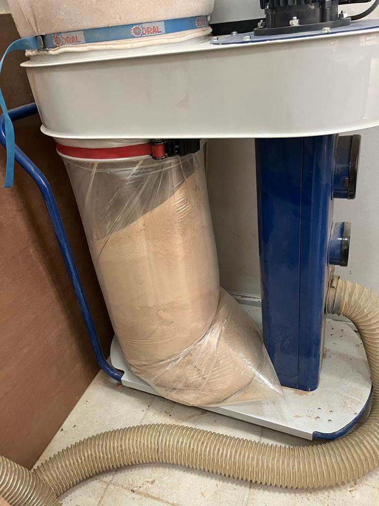
3- There should be devices to clean the dust of the cuts done on the wooden sheet, the following two pictures show the devices used for this purpose as to ensure there is no dust going off:
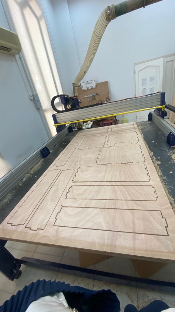
Then, the CNC machine was started to cut our designs:
Assembly process
After the CNC milling machine is done cutting :
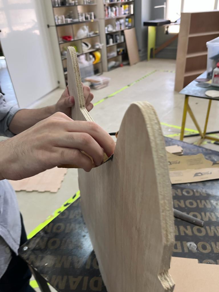
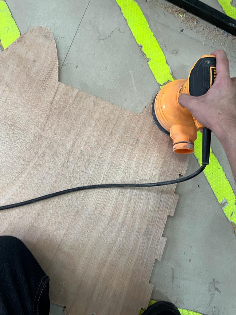
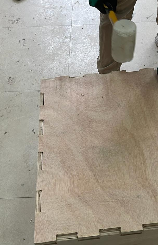
1- First, we have to clean the cutting parts from impurities and to be protect the wood pieces and to give the shape a luster and have a good texture where this was done by using sandpaper and sanding mechine:
2- I was used hammer to put the parts together to form the designated box . The box needed to be hit several times by the hammer to ensure its put intact:
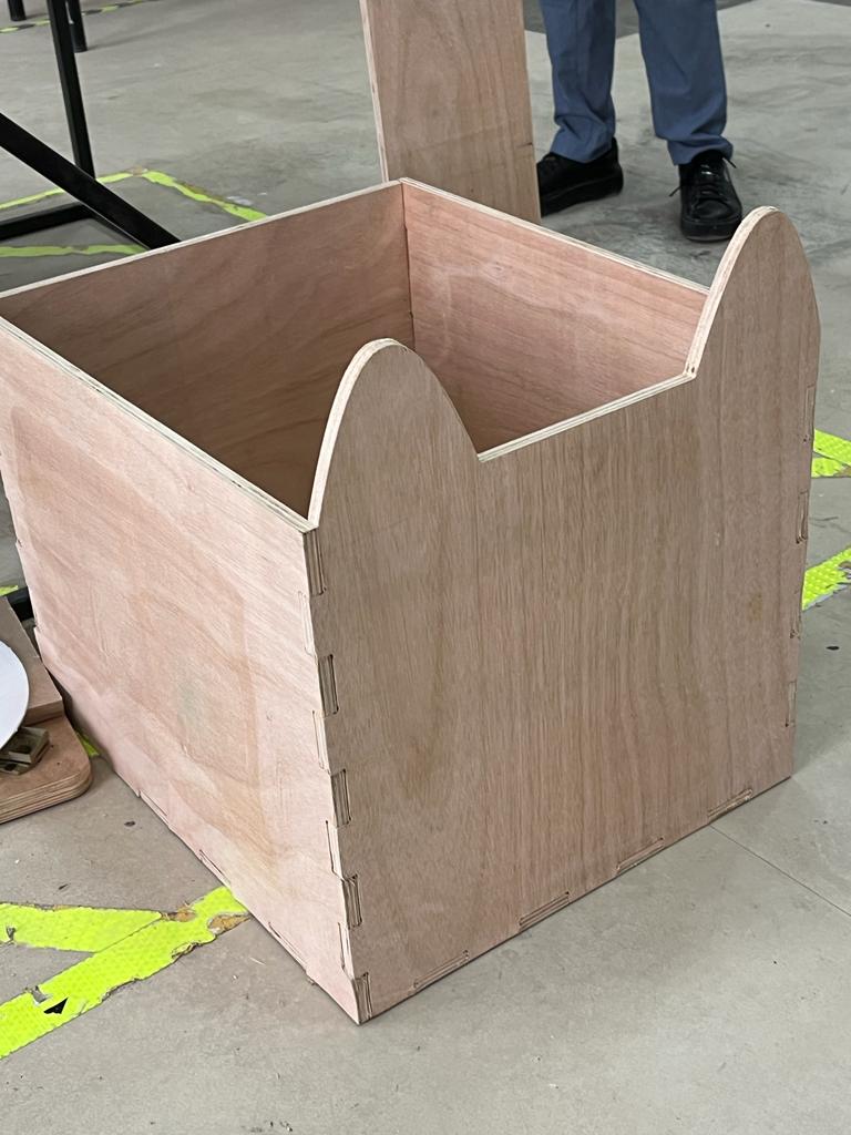
The final box looks like the following:
I would like to thank my colleague Islam for helping me in some parts of this assignment
CNC Group Assignment
In this group assignment, we are going to examine the procedure followed to test the important parameters affecting the CNC machine performance.
Feed and Speed Tests
To begin with, feeds specifically refers to the feed rate the tool advances through the material while speed refers to the surface speed that the cutting edge of the tool is moving and is needed to calculate the spindle RPM.
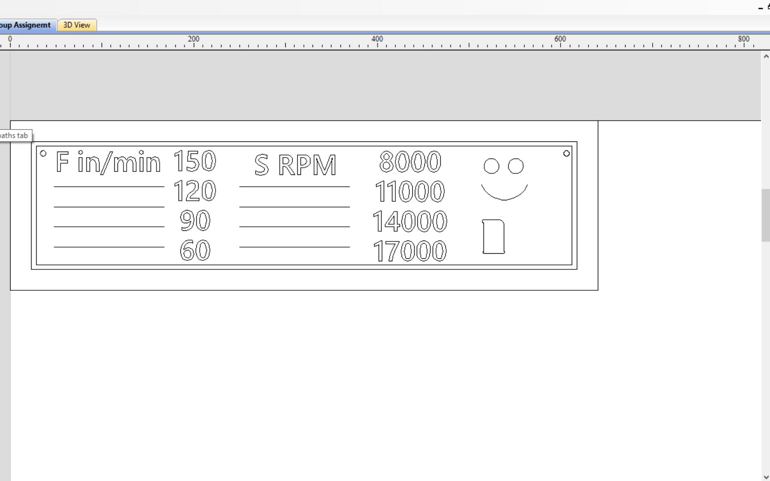
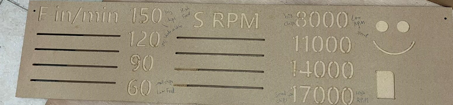
A wooden sheet was constructed with the feed rates and rotational speeds that are going to be tested.The feed rates range from 60 to 150 in/min and the rotational speed ranges from 8000 to 17000 RPM. When testing one parameter, the other is held constant.
Consequently, when testing the feed rate, the rotational speed is held at a constant value of 14000 RPM and when testing the rotational speed, the feed rate was held at a constant value of 80 in/min.
Notice that, when we run at high Feed we will get big chips of sawdust and when we run at low feed will get small chips of sawdust. regarding the speed the opposite is occuring which is when we run at low RPM will get big chips of sawdust and at high RPM will get small chips of sawdust .
So, we have to find the optimum value of both speed and feed.
Alignment Test
Aligning most CNC machinery can be critical for proper performance. If your goals in aligning CNC mills, lathes and gantries is to ensure accuracy or simply to prevent machine tool wear, a laser alignment system is the most precise way to do this.
If the mechine cuts and drills the shape (i.e rectangle) by 90 degree. So, we will know the Alignment is perfect.
Toolpaths
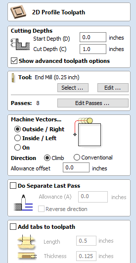
- Profile toolpath:
Profile Machining is used to cut around or along a vector. Options provide the flexibility for cutting shapes out with optional Tabs / bridges plus an Allowance over/undercut to ensure perfect edge quality.
Profile toolpaths can be outside, inside or on the selected vectors, automatically compensating for the tool diameter and angle for the chosen cut depth. the profile toolpath is shown is bellow:
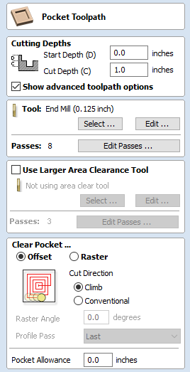
- Pocket toolpath:
A Pocketing operation is used when you want remove all material with a closed boundary down to a set depth. Pockets can be programmed to cut through the full-depth of the materials or partial depth.
In order to add pocket to the wooden sheet, the pocket toolpath is used, the main difference between the casual toolpath used for cutting and the pocket toolpath used to add pockets is that in the latter the depth is specified as the depth of the pocket. The following picture illustrates the pocket toolpath:
Also, The drilling toolpath is used in order to add holes to the wooden sheet. The drilling toolpath can be accessed from the toolpath operation. The same settings to the profile toolpath is used (i.e. same depth) with the only difference is the feed rate.
The following picture shows the design used for testing:
This is the final design after using the CNC machine to make it:
I did not face any issues since my design was very simple and I followed the steps for the cutting and assembling and it was a strightforward